

Hi everyone, I'd like to experiment with diode brakes on one of my controllers. I have a friend who has tried them, and he's told me what he's done, but I thought I'd ask and see what others recommend, too.
How many steps (diodes) do I need for a good range? I'm mostly running 4" Flexis of several varieties, and I generally run less than half brake, sometimes very little, on my Difalco DD281 with the 3 ohm "pro" rheostat, so I would probably lean more toward less brakes than more.
How much current do the brake components need to be able to handle? Like I said, I'm generally running 4" Flexis, but I do play with cars with up to X-12 motors, so I do want to be able to handle them, too.
Any recommendations for specific diodes? I did find that Dan Ruddock used a diode with a lower voltage drop for the first step on his diode brakes, but that's about all I've been able to come up with so far. Maybe it doesn't matter that much, as long as the diodes have a high enough amperage rating?
Any input would be much appreciated.

Diode brakes
Started by
rmjlmartin
, Sep 17 2023 07:16 PM
15 replies to this topic
#1

rmjlmartin
-
- Full Member
-

- 317 posts Joined: 26-December 20
On The Lead Lap
- Gender:Male
- Location:Gladys, VA
Posted 17 September 2023 - 07:16 PM
Jason Martin
#2
Jim Difalco
-

- Advertiser
-
- 673 posts Joined: 20-December 08
Race Leader
- Gender:Male
- Location:Jensen Beach, Florida
Posted 17 September 2023 - 10:25 PM
Jason, no offense, but why do you want to bother replacing a brake rheostat that has about 40 different choices (bands) on my pro brake or 100 or so choices on a standard brake rheostat with even 8 to 10 diodes? You will find that you will turn the diode brake to setting 7 and have too much brakes then turn it to setting 8 (for example) and have too little brakes. You will not be able to fine tune your brakes like a regular rheostat.
I know you are kind of a lover of controller fiddling but I think you will be unhappy with the results.
In case you ignore my advice even a 1 amp diode would be fine to experiment with. I think Dan used a 6 position switch and of course the first position was full brakes. Not sure why Dan even tried a diode brake. Maybe he thought it was less costly? He abandoned it after a short while and went back to a rheostat.
- Tim Neja, NSwanberg, SpeedyNH and 2 others like this
Jim Difalco
Difalco Design
3075 NE Loquat Lane
Jensen Beach, FL 34957
(772) 334-1987
askjim@difalcoonline.com
#3
rmjlmartin
-
- Full Member
-
- 317 posts Joined: 26-December 20
On The Lead Lap
- Gender:Male
- Location:Gladys, VA
Posted 18 September 2023 - 11:03 AM
Thanks Jim, no offense taken. And to be completely honest, I'm expecting this to be temporary experiment, not a permanent modification. But I'd like to try it.
You're right that I like to tinker. It's how I learn and understand how things work. I always understand better how things work and why things are done different ways by different people by experimenting. So that's the reason for the experiment, not that I think diode brakes are going to be the magic bullet that will make me faster than anyone else.
- Jim Difalco likes this
Jason Martin
#4
drrufo
-

- Full Member
-
- 359 posts Joined: 26-January 13
DR Racing Products
- Gender:Male
- Location:Orange County, CA
Posted 18 September 2023 - 01:03 PM
The six diode was an option on the dr-40. It allowed the racer to choose a position rather guessing. The middle diodes could be different values for different braking. I don't guess, I built the controllers after I bought the design from Dan.
John Andersen
DR Racing Products
#5
Jim Difalco
-
- Advertiser
-
- 673 posts Joined: 20-December 08
Race Leader
- Gender:Male
- Location:Jensen Beach, Florida
Posted 18 September 2023 - 02:05 PM
The six diode was an option on the dr-40. It allowed the racer to choose a position rather guessing. The middle diodes could be different values for different braking. I don't guess, I built the controllers after I bought the design from Dan.
Better to guess from 40 or 100 choices than to be limited to 6 choices.
Jim Difalco
Difalco Design
3075 NE Loquat Lane
Jensen Beach, FL 34957
(772) 334-1987
askjim@difalcoonline.com
#6
Eddie Fleming
-

- Subscriber
-
- 2,924 posts Joined: 27-April 14
Posting Leader
- Gender:Male
- Location:Fayetteville, GA USA
Posted 18 September 2023 - 03:33 PM
I looked at the diode brake thing some time back, but never tried it.
The thing that interested me was the way the brake is suppose to react rather than the amount of adjustment. As I understand it the brakes slow the car until the voltage created by the motor spinning drops below the adjustment threshold and then the brakes release. At least that was the way I understood it.
I am still curious to know from anyone that has tried Diode brakes Can the effect be felt and do the brakes have a different feel?
That said I am very happy with the brakes on my Difalco controllers.
- rmjlmartin and Sloter like this
Eddie Fleming
#7
Rob Voska
-

- Subscriber
-
- 1,121 posts Joined: 12-April 08
Checkered Flag in Hand
- Gender:Male
Posted 18 September 2023 - 04:12 PM
Easy to understand instructions here. You only need the brake part of the article. It gives roll on braking when as the car slows the brake power is reduced. I ran it for years but in C can and higher stuff that has a lot of brake. FK motors with big pinions might not work as well. Parts are easy sourced on ebay or Digikey.
Ruddick built a different style diode brake. .
http://www.chaskeeli...ng_your_own.htm
If you make this one use a weaker spring.
- rmjlmartin likes this
#8
Bill Seitz
-

- Subscriber
-
- 582 posts Joined: 20-February 21
Still Half-Fast After All These Years
- Gender:Male
- Location:Tucson, AZ
Posted 18 September 2023 - 06:17 PM
I've done some experimenting with diode brakes mostly because of the reported "brake and release" feature. After trying a variety of cars on different tracks with different braking requirements, I've come to the conclusion there's no advantage of using diodes. As Jim Difalco smartly suggested, why give up a very simple pot implementation with a more sensitive range of adjustment than a few diodes provides. As far as I can tell, "brake and release" is entirely theoretical based on a misunderstanding of how diodes work and, for all practical purposes, doesn't exist with diode brakes. What makes the diode "release" is its forward voltage drop. Some people assume or consider that this is a fixed voltage, typically .7 volts. However, the forward voltage is dependent on current and can be higher or lower than the typical .7 value depending on how much current is flowing through the diode. As the current diminishes, so does the cutoff or "release" point. As far as I can tell from simple tests running cars with the diodes, if there is a cutoff/release point, it occurs when the car is traveling so slowly that there's not much braking action anyway. Since this was the only advantage I could see for using diodes, and it wasn't evident in the testing I performed, I will be abandoning diode brakes in the one controller in which I was trying them.
The current dependent nature of diode forward voltage also reeks havoc on diode throttle control. I remember claims for diode controllers that they self-adjusted to different performance motors. Actually, they have the same problem, though possibly to a lesser extent, as resistor controllers. The voltage drop across each diode increases as the motor draws more current, the reverse of what is actually needed. Diode controllers aren't good choices where a wide range of motor types/performance levels will be used. As with resistor controllers, it's likely that multiple diode controllers would be required or some circuitry switching diodes in and out for sensitivity control would be necessary. While I did consider a diode throttle control, the added complexity caused me to abandon that approach a long time ago.
In the past, I also tried a PWM brake circuit, and for the added complexity PWM created, it was no more valuable than the simple pot. I'll be trying some other electronic braking circuits in the future more to satisfy my engineer's curiosity than anything, but for the moment, the tried, true, and simple resistive pot works as well as anything.
- JerseyJohn, Rob Voska, CDavis7 and 3 others like this
#9
Ramcatlarry
-

- Subscriber
-
- 2,945 posts Joined: 08-March 06
Posting Leader
- Gender:Male
- Location:Barrington, IL 60010
Posted 18 September 2023 - 07:51 PM
You may have forgoten the OMNI controllers. You had a choice of two positions plus full brakes. I have always liked the first step for oval racing, myself.
The easy test is to use two diodes and one alligator clip. Wire them in series so that you can clip your controller RED wire to either one or both diodes. Test the direction because the stripe on the diode has to be in the right direction for it to affect the brakes. If you hook them up backwards, it still makes a nice 'choke' for little kids to slow them down (on the BLACK)) - if you use at least a 3 amp diode.
- Rob Voska, John Luongo and rmjlmartin like this
Larry D. Kelley, MA
retired raceway owner... Raceworld/Ramcat Raceways
racing around Chicago-land
Diode/Omni repair specialist
USRA 2023 member # 2322
IRRA,/Sano/R4 veteran, Flat track racer/MFTS
Host 2006 Formula 2000 & ISRA/USA Nats
Great Lakes Slot Car Club (1/32) member
65+ year pin Racing rail/slot cars in America
#10
parocket
-

- Full Member
-
- 283 posts Joined: 28-February 11
ASSCC
- Gender:Male
- Location:PA
Posted 20 September 2023 - 08:39 AM
I have the diode pod for brakes. It is exactly like Jim mentioned. Hard to get the correct feel do to much or to little brakes. I will say an inexperienced racer who never used the rheostat type might not know the difference. That is my experience here at our track.
#11
Jim Difalco
-
- Advertiser
-
- 673 posts Joined: 20-December 08
Race Leader
- Gender:Male
- Location:Jensen Beach, Florida
Posted 20 September 2023 - 09:34 AM
You may have forgoten the OMNI controllers. You had a choice of two positions plus full brakes. I have always liked the first step for oval racing, myself.
The easy test is to use two diodes and one alligator clip. Wire them in series so that you can clip your controller RED wire to either one or both diodes. Test the direction because the stripe on the diode has to be in the right direction for it to affect the brakes. If you hook them up backwards, it still makes a nice 'choke' for little kids to slow them down (on the BLACK)) - if you use at least a 3 amp
Not that anyone is going to be making a diode choke for kids, but you want to install it on the white alligator clip. Putting a diode on the black clip will reduce the brakes when engaged. This goes for wires chokes as well. Les Wright put his wire chokes on the black track side last time I had one.
- Ramcatlarry likes this
Jim Difalco
Difalco Design
3075 NE Loquat Lane
Jensen Beach, FL 34957
(772) 334-1987
askjim@difalcoonline.com
#12
rmjlmartin
-
- Full Member
-
- 317 posts Joined: 26-December 20
On The Lead Lap
- Gender:Male
- Location:Gladys, VA
Posted 30 March 2024 - 09:29 PM
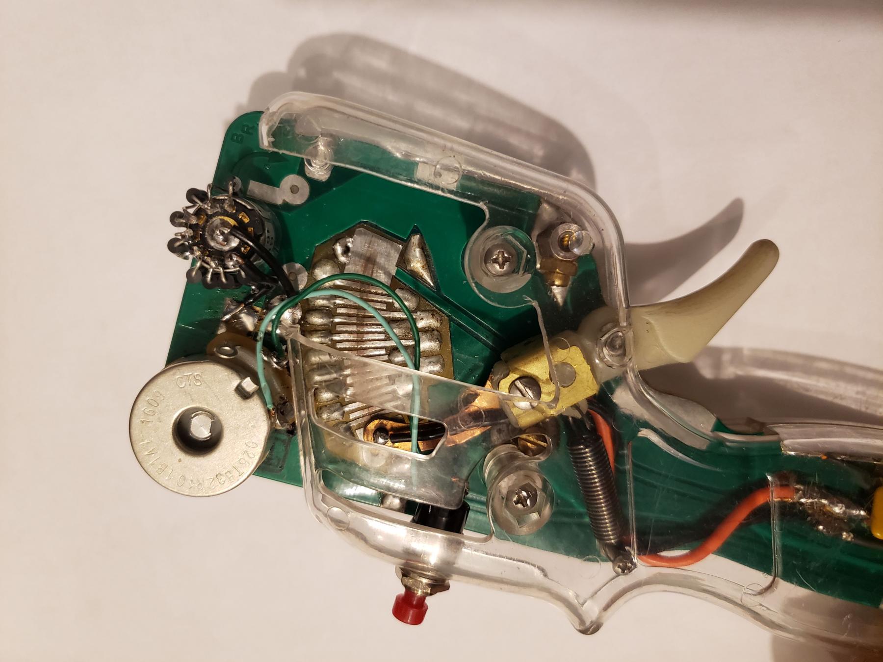
I guess It's probably time that I take a minute and update this, since I've now experimented with it a bit.
I installed an 8-position switch on a spare controller, have tried several variations of diode configurations, and raced with it a time or two. I'll attach a couple of pictures for reference. The switch is a Grayhill 56 series switch, and I used 1N4001 diodes that I had on hand. The switch is rated for 200ma, and I believe the diodes are 1A, so that may not be suitable for higher-powered cars, but they worked for my test. That was just what I was able to get my hands on readily and inexpensively.
I wired the switch with the first position as full brake, and the last position with no brake, and six diodes steps. I started with one diode on each position, but that didn't give me quite the adjustment range I wanted, so I tried a couple different combinations, and ended up with two diodes each in the first two steps down from full brake, and one in each of the others. I tried three steps with two diodes, but didn't think I could really tell any difference in the last couple of steps, so I went back to two.
Jim Difalco is right that it is a very limited number of steps compared to a 5w pot or 12w rheostat. However, I personally didn't find that to really be an issue for me with the cars I've run it with, because of the different feel. An old Cidex instruction sheet that I have calls their diode brake a "threshold" brake, that brakes to a point, then allows the car to coast, and I can tell that it does do that. (I don't know if that's a technically correct explanation, but it does seem to feel like that.) So definitely a slightly different feel than the pot most people have used for a long time.
I'd say it was definitely worth the experiment. I don't have any plans to convert all of my other controllers, but I'll leave the diodes in this one for now, at least. I've had no issues with the "normal" brakes in my Difalco controllers, but it's a little different, so unless I need to do something else with this controller, I'll consider it another tool in my toolbox.
Bottom line, I don't know if it's "better" or "worse" than a traditional pot or rheostat, but I'd say it's worth giving it a try. Whether or not you like it better will probably depend on how much you like the feel, and how the limited number of positions work for you.
Attached Images

- Rob Voska, SpeedyNH, John Luongo and 1 other like this
Jason Martin
#13
gotboostedvr6
-

- Full Member
-
- 2,321 posts Joined: 19-July 11
Posting Leader
- Gender:Male
- Location:Mt. Laurel
Posted 31 March 2024 - 08:22 AM
Im testing diode brakes this week. Will also share my experience
- Rob Voska and rmjlmartin like this
David Parrotta
#14
Bill from NH
-

- Full Member
-
- 14,759 posts Joined: 02-August 07
Age scrubs away speed!
- Gender:Male
- Location:New Boston, NH
Posted 31 March 2024 - 09:44 PM
Is this the same switch Dan Ruddock offered on the last of his controllers when he manufactured them?
Bill Fernald
I intend to live forever! So far, so good.
I intend to live forever! So far, so good.
#15
Eddie Fleming
-
- Subscriber
-
- 2,924 posts Joined: 27-April 14
Posting Leader
- Gender:Male
- Location:Fayetteville, GA USA
Posted 01 April 2024 - 07:25 AM
Jason as far as I can tell it looks like the two diodes on positions one and two are parallel not in series. is that correct?
Eddie Fleming
#16
rmjlmartin
-
- Full Member
-
- 317 posts Joined: 26-December 20
On The Lead Lap
- Gender:Male
- Location:Gladys, VA
Posted 01 April 2024 - 08:09 AM
Is this the same switch Dan Ruddock offered on the last of his controllers when he manufactured them?
Bill, I don't know the exact details of what Dan Ruddock used, but it's the same idea.
Jason as far as I can tell it looks like the two diodes on positions one and two are parallel not in series. is that correct?
The two diodes are in series. I don't know if the picture is clear enough if you enlarge it, but the silver stripe is on top on one of the diodes, and on the bottom on the other, and the bottom legs of the two diodes are connected together.
Jason Martin


