Jump to content


Photo

Koford M641 resistance reversed!


  • Please log in to reply
21 replies to this topic

#1 Alf Bird

Alf Bird

    Rookie Keyboard Racer

  • Full Member
  • Pip
  • 12 posts
  • Joined: 26-June 24
  • Gender:Male
  • Location:NSW, Australia

Posted 26 June 2024 - 06:18 PM

For some strange reason, the resistance is higher the further up the scale (towards full power) I go when measured with a digital multimeter set on ohms.


I also have a Difalco controller to compare it with and that reads as it should; the further up the scale, the less resistance. As you would expect when I put a car on the track nothing happens until I get further up the scale (near the end) and the car takes off; not with the Difalco though.


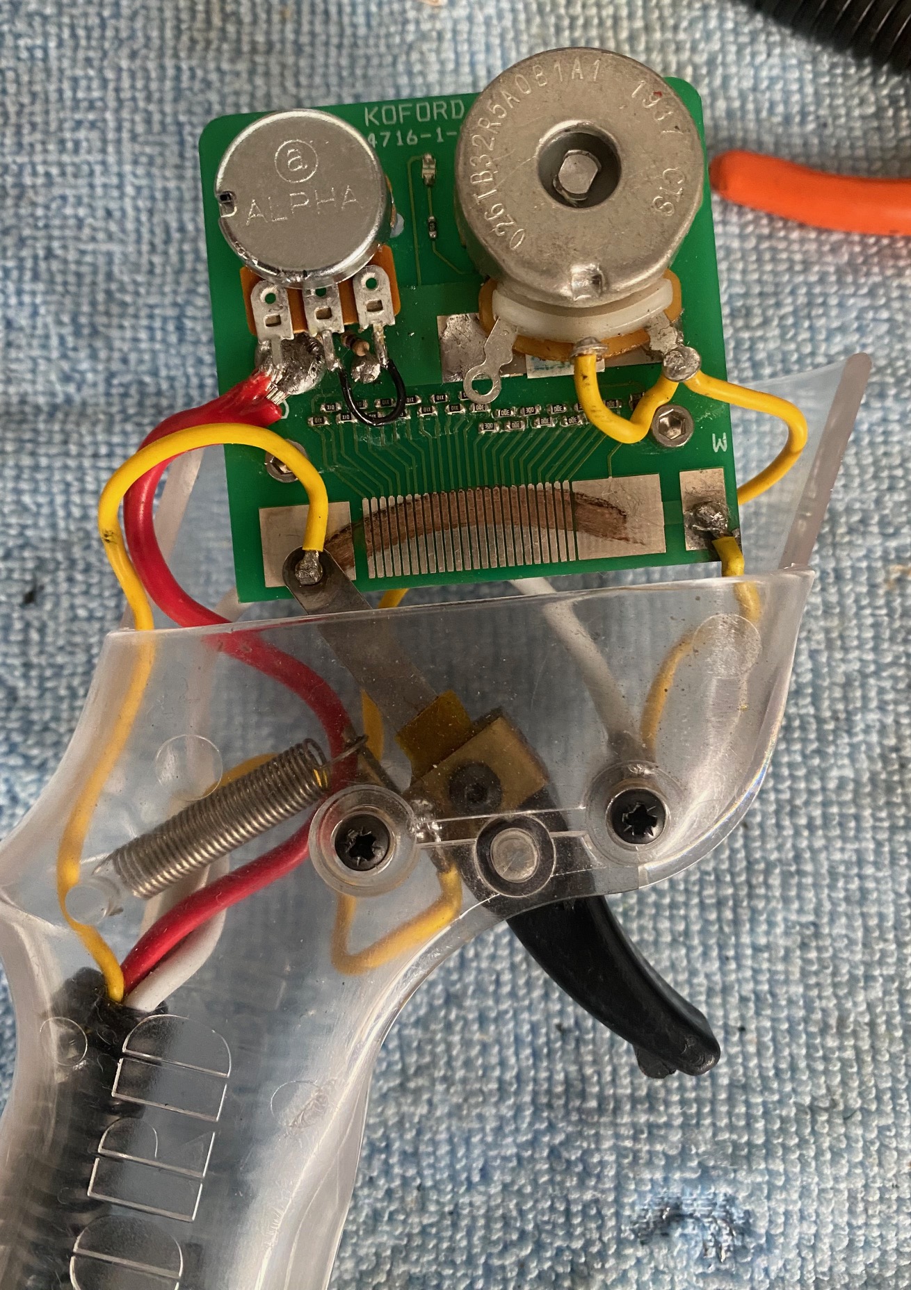
Both controllers are the same polarity, both digital, same cars used (rear wheels held off track), track is braided wooden. One photo shows the sensitivity pot on the left and the brake pot on the right; the sensitivity pot has been changed since the issue commenced as it was faulty.


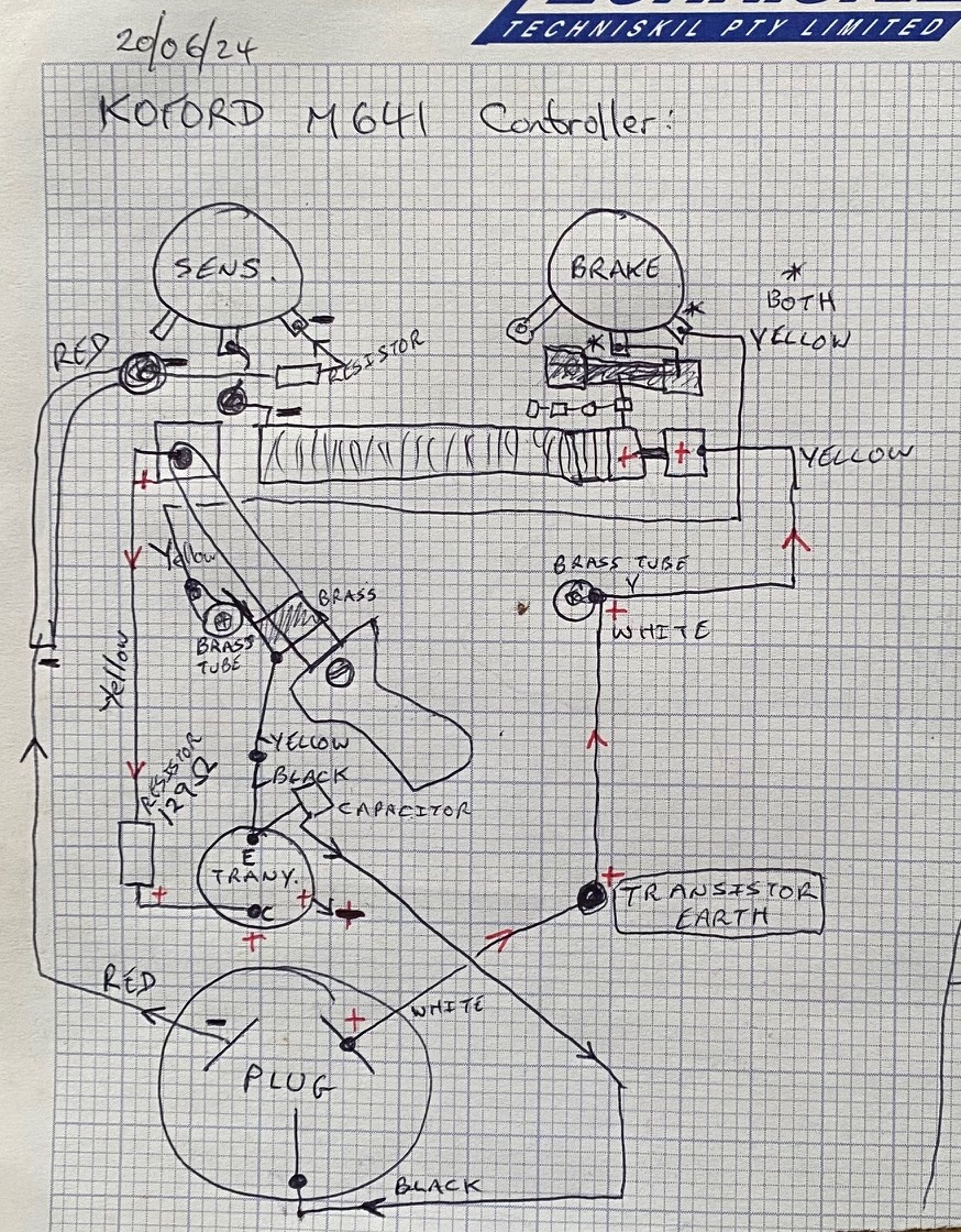
The other photo is my attempt at a rough schematic. Any thoughts or suggestion what may be causing this to happen, it's doing my head in  :dash2:


Thanks in advance.


IMG_5107.jpg


Schematic.jpg


#2 Racer36

Racer36

    Checkered Flag in Hand

  • Full Member
  • PipPipPipPipPipPip
  • 1,372 posts
  • Joined: Today, 04:54 PM
  • Gender:Male
  • Location:Ontario,Canada

Posted 26 June 2024 - 08:09 PM

Where did you get the Koford controller from? The soldering and wiring does not look like factory work.


  • Rob Voska and Roy Lievanos like this

#3 Alf Bird

Alf Bird

    Rookie Keyboard Racer

  • Full Member
  • Pip
  • 12 posts
  • Joined: 26-June 24
  • Gender:Male
  • Location:NSW, Australia

Posted 27 June 2024 - 02:10 AM

Private sale. Twas working though.

#4 mreibman

mreibman

    Race Leader

  • Full Member
  • PipPipPipPipPip
  • 633 posts
  • Joined: 19-March 18
  • Gender:Male
  • Location:Merrick, NY

Posted 27 June 2024 - 04:49 AM

Move the yellow wire from the right leg to the left leg and retry. Leave the center leg alone.
Mike Reibman
Alleged amateur racer.
Mostly just play with lots of cars.
Able to maintain slot cars with a single bound.
Faster than a speeding Womp.
More powerful than a 36D.


#5 mreibman

mreibman

    Race Leader

  • Full Member
  • PipPipPipPipPip
  • 633 posts
  • Joined: 19-March 18
  • Gender:Male
  • Location:Merrick, NY

Posted 27 June 2024 - 06:22 AM

Also, in your diagram, the sense and brake are transposed. Red wire goes to brake pot, yellow to sensitivity.
Mike Reibman
Alleged amateur racer.
Mostly just play with lots of cars.
Able to maintain slot cars with a single bound.
Faster than a speeding Womp.
More powerful than a 36D.


#6 Jim Difalco

Jim Difalco

    Race Leader

  • Advertiser
  • PipPipPipPipPip
  • 673 posts
  • Joined: 20-December 08
  • Gender:Male
  • Location:Jensen Beach, Florida

Posted 27 June 2024 - 06:41 AM

Find a picture of a factory fresh model and copy the wiring. The rheostats are reversed. Looks like the sensitivity rheostat should be soldered direct to the pcb? Not sure how the wiper button will make good contact with the bands with that big yellow wire soldered to it and pulling on it.


  • mreibman likes this

Jim Difalco
Difalco Design
3075 NE Loquat Lane
Jensen Beach, FL 34957
(772) 334-1987
askjim@difalcoonline.com


#7 Alf Bird

Alf Bird

    Rookie Keyboard Racer

  • Full Member
  • Pip
  • 12 posts
  • Joined: 26-June 24
  • Gender:Male
  • Location:NSW, Australia

Posted 27 June 2024 - 05:41 PM

Move the yellow wire from the right leg to the left leg and retry. Leave the center leg alone.

If I do that it's only reversing the braking on the pot, "1" will be maximum braking instead of "10" and visa versa.


#8 Alf Bird

Alf Bird

    Rookie Keyboard Racer

  • Full Member
  • Pip
  • 12 posts
  • Joined: 26-June 24
  • Gender:Male
  • Location:NSW, Australia

Posted 27 June 2024 - 05:44 PM

Also, in your diagram, the sense and brake are transposed. Red wire goes to brake pot, yellow to sensitivity.

I've just seen on-line, another Koford M641 and it is wired exactly the same; I'm contemplating purchasing it as I will need another controller when I make my 4 lane track.


#9 Alf Bird

Alf Bird

    Rookie Keyboard Racer

  • Full Member
  • Pip
  • 12 posts
  • Joined: 26-June 24
  • Gender:Male
  • Location:NSW, Australia

Posted 27 June 2024 - 05:49 PM

Find a picture of a factory fresh model and copy the wiring. The rheostats are reversed. Looks like the sensitivity rheostat should be soldered direct to the pcb? Not sure how the wiper button will make good contact with the bands with that big yellow wire soldered to it and pulling on it.

I've just seen on-line, another Koford M641 and it is wired exactly the same; I'm contemplating purchasing it as I will need another controller when I make my 4 lane track. The Sensitivity pot gets power via the red wire with a resistor soldered to the right leg, it then exits the pot via the middle leg with a wire soldered to the PCB.


#10 Alf Bird

Alf Bird

    Rookie Keyboard Racer

  • Full Member
  • Pip
  • 12 posts
  • Joined: 26-June 24
  • Gender:Male
  • Location:NSW, Australia

Posted 28 June 2024 - 04:09 AM

Find a picture of a factory fresh model and copy the wiring. The rheostats are reversed. Looks like the sensitivity rheostat should be soldered direct to the pcb? Not sure how the wiper button will make good contact with the bands with that big yellow wire soldered to it and pulling on it.


#11 Alf Bird

Alf Bird

    Rookie Keyboard Racer

  • Full Member
  • Pip
  • 12 posts
  • Joined: 26-June 24
  • Gender:Male
  • Location:NSW, Australia

Posted 28 June 2024 - 04:13 AM

Ive seen another M641 and its exactly the same, Ive purchased it and will receive it next week so all going well Ill find out what the issue is. The wiper does make good contact and the wire is quite pliable and is free to move about so no problem there. Cheers

#12 Jim Difalco

Jim Difalco

    Race Leader

  • Advertiser
  • PipPipPipPipPip
  • 673 posts
  • Joined: 20-December 08
  • Gender:Male
  • Location:Jensen Beach, Florida

Posted 28 June 2024 - 06:37 AM

I reread your first post again. So you are actually saying the car does not get power on the bands until pulled to almost full power? Maybe you should be looking for a blown transistor instead.


  • Eddie Fleming likes this

Jim Difalco
Difalco Design
3075 NE Loquat Lane
Jensen Beach, FL 34957
(772) 334-1987
askjim@difalcoonline.com


#13 Alf Bird

Alf Bird

    Rookie Keyboard Racer

  • Full Member
  • Pip
  • 12 posts
  • Joined: 26-June 24
  • Gender:Male
  • Location:NSW, Australia

Posted 28 June 2024 - 05:00 PM

I reread your first post again. So you are actually saying the car does not get power on the bands until pulled to almost full power? Maybe you should be looking for a blown transistor instead.


#14 Alf Bird

Alf Bird

    Rookie Keyboard Racer

  • Full Member
  • Pip
  • 12 posts
  • Joined: 26-June 24
  • Gender:Male
  • Location:NSW, Australia

Posted 28 June 2024 - 05:06 PM

Thanks Jim yes that is correct. Im glad you mentioned the transistor. I initially suspected that so I removed it and tested it and it appeared to be ok using info off Google to test it however there was some conflicting info so Im not totally happy with the result so yes it could be the transistor. Ill carry out a comparison when I receive the other M641 later next week I hope

#15 Bill Seitz

Bill Seitz

    Still Half-Fast After All These Years

  • Subscriber
  • PipPipPipPipPip
  • 579 posts
  • Joined: 20-February 21
  • Gender:Male
  • Location:Tucson, AZ

Posted 28 June 2024 - 05:25 PM

I was also thinking a transistor problem, though usually transistors are either open or shorted. There's a couple other curiosities that could be at fault. There's a PTC in the circuit near the Emitter that Alf has labeled as a capacitor. These "thermal circuit breakers" once activated may never return to their original low resistance state. If it reads more than a fraction of an ohm, I'd replace it. The other is a 129 ohm resistance in the Base circuit (Alf has it labeled as "C" on the transistor, but this has to be the Base) which would drastically reduce the input to the transistor. I see no reason for it - another failed PTC? There's a couple more potential solder connection issues. The red wire is nasty - has melted while soldering, and turned into a splayed blob of soldered wire, a potential short. I'd clean up this joint and make sure it's only connected to the one place it's supposed to be.  The red wire looks like it's connected to a pot terminal, and it should not be. On the other pot, the 2 yellow wires seem to be another potential short condition. Alf's schematic also makes it appear the brake pot is somehow connected to the throttle circuit network which it shouldn't be. Both the sensitivity pot and the brake pot should have a connection to the red wire which also provides the ground (V-) connection.


It's also important to realize that there are multiple ways to wire a controller even though the operating principal is common. Using one brand as a wiring pattern and troubleshooting aid for another can lead to inadvertent mis-wires and further damage.


#16 Alf Bird

Alf Bird

    Rookie Keyboard Racer

  • Full Member
  • Pip
  • 12 posts
  • Joined: 26-June 24
  • Gender:Male
  • Location:NSW, Australia

Posted 28 June 2024 - 07:36 PM

I was also thinking a transistor problem, though usually transistors are either open or shorted. There's a couple other curiosities that could be at fault. There's a PTC in the circuit near the Emitter that Alf has labeled as a capacitor. These "thermal circuit breakers" once activated may never return to their original low resistance state. If it reads more than a fraction of an ohm, I'd replace it. The other is a 129 ohm resistance in the Base circuit (Alf has it labeled as "C" on the transistor, but this has to be the Base) which would drastically reduce the input to the transistor. I see no reason for it - another failed PTC? There's a couple more potential solder connection issues. The red wire is nasty - has melted while soldering, and turned into a splayed blob of soldered wire, a potential short. I'd clean up this joint and make sure it's only connected to the one place it's supposed to be.  The red wire looks like it's connected to a pot terminal, and it should not be. On the other pot, the 2 yellow wires seem to be another potential short condition. Alf's schematic also makes it appear the brake pot is somehow connected to the throttle circuit network which it shouldn't be. Both the sensitivity pot and the brake pot should have a connection to the red wire which also provides the ground (V-) connection.
 
It's also important to realize that there are multiple ways to wire a controller even though the operating principal is common. Using one brand as a wiring pattern and troubleshooting aid for another can lead to inadvertent mis-wires and further damage.


#17 Alf Bird

Alf Bird

    Rookie Keyboard Racer

  • Full Member
  • Pip
  • 12 posts
  • Joined: 26-June 24
  • Gender:Male
  • Location:NSW, Australia

Posted 28 June 2024 - 07:50 PM

Thanks very much for that informative information, I will check out the controller thoroughly when I have received the other used M641 controller later next week. I can see that the wiring appears to be exactly the same as the one with issues (except the soldering work) however I should know for certain what the issue is after some testing. I should have pointed out earlier that the B, C & E on the transistor were written prior to me removing the transistor for testing so they are incorrect. I THINK that the yellow wire with resistor connects to Base, the black to the Emitter and the white to the Collector (one screw of the transistor metal cover). Cheers

#18 Alf Bird

Alf Bird

    Rookie Keyboard Racer

  • Full Member
  • Pip
  • 12 posts
  • Joined: 26-June 24
  • Gender:Male
  • Location:NSW, Australia

Posted 14 July 2024 - 09:32 PM

Update. I removed the transistor and carried out testing as per information from Google; it failed at step 3. I ordered a new transistor and upon receipt tested it using the same method; it also failed at step 3 however I soldered in place but to no avail. The other identical controller arrived and works as it should. I cannot find any differences in the two except for one works and one doesnt. Next step is to hand them both to an electronics wise friend and see what he comes up with. Once sorted (fingers crossed) Ill post the results here.

#19 stoo23

stoo23

    Race Leader

  • Full Member
  • PipPipPipPipPip
  • 553 posts
  • Joined: 26-July 08
  • Gender:Male
  • Location:Sydney, Australia

Posted 15 July 2024 - 04:50 AM

Damn that controller has some nasty soldering :(


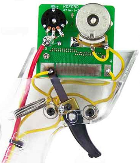
I think I ewould be trimming the ends and cleaning things up neatly and re-soldering everything, after checking Both 'Pots' etc and maybe 'Marking' all those Yellow wires (so you can tell them apart !!) ... I mean honestly Who the hell, thought this was Clever ??


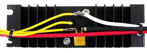
KOF-M641-5_sml.jpg


Then I would try and make the controller 'look' like this :)


KOF-M641_sml.jpg


:)


Wow, after posting this, I noticed the 'state' of the Wiper board !!! ... Eeeek,.. that was off the E-Slotcar site :(


  • Jim Difalco likes this

Stewart Amos

Old Racer from Sydney, Australia
FASTUFF Race Proven Products


https://ascra.au


#20 Jim Difalco

Jim Difalco

    Race Leader

  • Advertiser
  • PipPipPipPipPip
  • 673 posts
  • Joined: 20-December 08
  • Gender:Male
  • Location:Jensen Beach, Florida

Posted 15 July 2024 - 06:07 AM

Damn that controller has some nasty soldering :(


I think I ewould be trimming the ends and cleaning things up neatly and re-soldering everything, after checking Both 'Pots' etc and maybe 'Marking' all those Yellow wires (so you can tell them apart !!) ... I mean honestly Who the hell, thought this was Clever ??


attachicon.gif KOF-M641-5_sml.jpg


Then I would try and make the controller 'look' like this :)


attachicon.gif KOF-M641_sml.jpg


:)


Wow, after posting this, I noticed the 'state' of the Wiper board !!! ... Eeeek,.. that was off the E-Slotcar site :(

after seeing this post from Stewart I notice some things. The "capacitor" on the heatsink track wire is an auto reset fuse. Since it is inline on the black track wire it is adding resistance to the brake circuit and to the full power operation not to mention the yellow wires are only 18 gauge adding more resistance to the full power circuit. The fuse is big enough to handle a short on the power side but is way too high an amperage to offer any protection to the brake rheostat.


the Eeeek comment by Stewart is probably because the PCB was possibly wave soldered and solder got on the wiper bands and had to be sanded off to make the bands smooth enough to use.


  • stoo23 likes this

Jim Difalco
Difalco Design
3075 NE Loquat Lane
Jensen Beach, FL 34957
(772) 334-1987
askjim@difalcoonline.com


#21 team burrito

team burrito

    Posting Leader

  • Full Member
  • PipPipPipPipPipPipPip
  • 2,202 posts
  • Joined: 15-September 06
  • Gender:Male
  • Location:SF Bay area

Posted 15 July 2024 - 02:09 PM

buy a difalco - problem solved.


  • Ramcatlarry, stoo23 and Dave_12 like this
Russ Toy (not Troy)
First Place Loser in the JK Products
International D3 Builders Competition

#22 Dave_12

Dave_12

    Mid-Pack Racer

  • Full Member
  • PipPipPip
  • 110 posts
  • Joined: 06-June 24
  • Gender:Male
  • Location:Sydney Australia

Posted 24 October 2024 - 01:10 AM

that board is very dirty definitely needs a clean 


David Rees


Electric Dreams Online Shop