Jump to content


Photo

DIY MOSFET/PWM brake system


  • Please log in to reply
2 replies to this topic

#1 slohand42

slohand42

    Rookie Keyboard Racer

  • Full Member
  • Pip
  • 3 posts
  • Joined: 04-March 25
  • Gender:Male
  • Location:FL

Posted 04 March 2025 - 02:18 PM

Let me first say, I have scoured the internet, slot forums and anything else I can imagine to find the answer to this question, only to be frustrated.

I am a tinderer, and have built my own controller based on Buknell's design. It works great, but I would like to go further into controller theory and build.

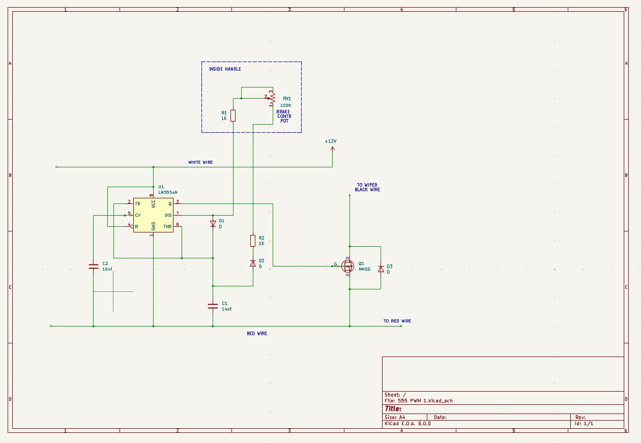
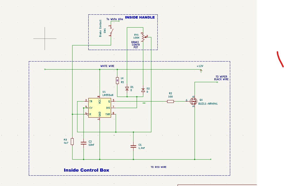
First, I would like to build a brake system that uses a mosfet in either variable resistor or PWM mode, but have only found one diagram for this. It uses a 555 timer which the designer, himself had some issues with.

Can anyone out there give me some direction, post a diagram/schematic, or point me in the right direction? I am experienced and knowledgeable enough to follow instruction, and schematics, and even brainstorm some things through, but not enough to develop my own circuits.

Thanks,

Slohand


Ted Robb


#2 slohand42

slohand42

    Rookie Keyboard Racer

  • Full Member
  • Pip
  • 3 posts
  • Joined: 04-March 25
  • Gender:Male
  • Location:FL

Posted 09 March 2025 - 06:29 PM

This is what I'm working on right now. A basic 555 PWM circuit with the divider pot being the brake adjustment pot in the controller handle. The rest will be housed in the electronics array down the cable near the track. The "Brake Adj Pot" will adjust the duty cycle of the 555. I agree that it won't reach full on or full off, but that doesn't worry me for brake application. Full brakes on my controller with the car I run is way overkill and I can rig up a relay or something is I want full off.
The values of the resistors and caps were configured with DigiKey's tool. This should get me 1000hz frequency with near full off/on range. We'll see. I invite any constructive input.
Thanks,
Ted


Attached Images

  • 555 PWM schem 1.jpg

Ted Robb

#3 slohand42

slohand42

    Rookie Keyboard Racer

  • Full Member
  • Pip
  • 3 posts
  • Joined: 04-March 25
  • Gender:Male
  • Location:FL

Posted 12 March 2025 - 12:48 PM

OK, here is what I think is to be the first working version of the project that I am going to test out. It uses the reset function of the 555 for turning the brake off and draining the plate voltage of the MOSFET. One of my aims was to get away from the large gage wire needed for a basic brake circuit in 1/24 scale racing. I am adding four 20 gage wires instead which will probably be a wash as far as total diameter goes, but I plan on using a 6 strand cable of 20 ga wires to the handle. The total diameter will be 1/4". I'll be busy in another life for a few days, so I'll probably have some feedback next week some time.


555 PWM Brake CCT 2.jpg


Ted Robb


Electric Dreams Online Shop