I like my Third Eye controller because of it's light weight, thin light cord and good trigger feel.
However, as the other guys where I race know, adjusting the brakes for any given car, can be difficult because the amount of braking changes a lot with only a small amount of knob turn when between 4 and 4 1/2 on the dial.
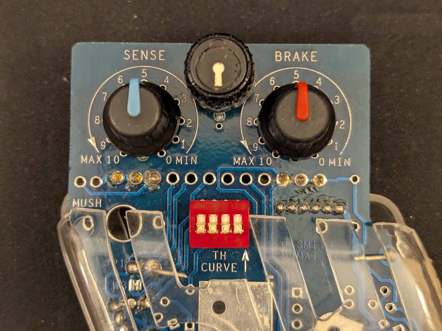
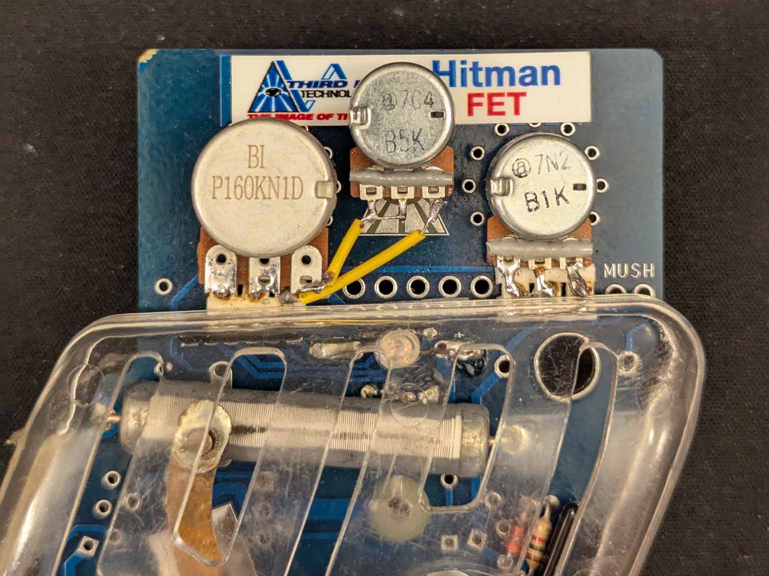
To solve this problem, I modified my Third Eye by moving the brake pot (a 5K pot) from it's original position and installing it in the middle of the board, then putting a 500 ohm pot in the brake position and wiring them in series.
So to adjust the brakes, the 5K pot (what I would call the range pot) is adjusted to bring the 500 ohm pot (the brake pot) into range so it can be used to fine tune the brake setting.
The knob on the range pot has detents so it makes the pot act like a rotary switch which is ideal for this type setup.
This past Friday I used the controller and got the impression that the range pot will stay in the same position for most of the cars we race and if a change is needed, it won't be more than a click or two.