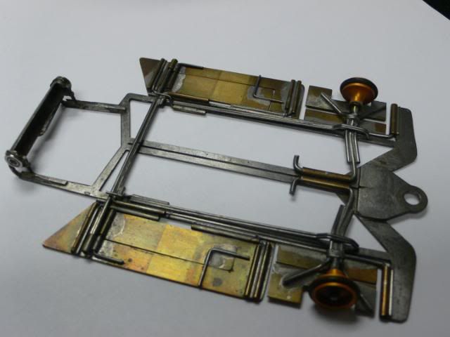
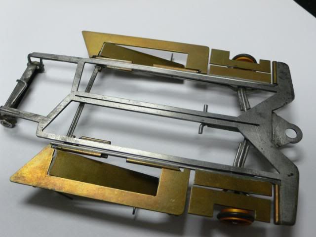
Joel the chassis is very similar to a west coast ISO modified Camen center section RTR chassis that was sold around 84-5. I am guessing an probaly wrong but it might be Mony Orens or some one from that local region as the was ISO chassis hotbed. The front tires when they lifted along with lifting that side pan bite bar pushed the center section down for traction. With the velocity of air going over the body action work more to give bite than to lift the bite bars and pans.
Tony the Herman pans (name may vari according to location) that were attched to the front wheel section were a exact copy of Paul Phifers 83 winning Nats chassis. The "Herman pans" were attached for weight distribution as mentioned but mostly to alter the weight to the center section. The springs were an important part of dampening and also limiters so the "L" axle would not fold back upon thierselves. also the forced the wheels down below the chassis when tilting in the corners. It also took the weight off the pans, plumber rails and placed it on the nose (hindge) of the center section. The springs also worked as a poor mans iso with bite bar interaction (if the bite bar was further forward). This was also the age of what was called the take apart chassis. The rear cross bar usually pulled out of a retaining tube) and the parts, such as each plummer bar plus pans could be dissaembled and altered at will. Some just soldered the bite bar tubes to the plumber rail without the take aart peature but gave it slop. The period correct motor is hard to pegg as there were so many motor changes in those years as cobalts redefined what cans were used. Ernie may have been using his narrowed C can polymer peanut motor or a Trinity square can cobalt motor. Pretty sure it then it was the Trinity Square can. Possibly even a PK/Camen RM640. It was'nt to far after 84 the one piece tripod shuttle or perimiter chassis came about
Mike is correct about cutting Jigs for spring steel. In the NW we used a Jig originating from an idea by a local racer Bob Maclehose. The unit involved using a large Drawer slide to attach the dremel tool to. It was allowed to rock a bit up and down. The bed that held the steel sheet was floated by using a minimum of 4 springs attached to base with adjustable wing bolts and "T" bolts. To that adjustable bed another two bolts clamped a bar that held down the steel sheet. Others had direct threaded beds that could be adjusted but I found the free floating sping adjusted dampend the vibration better while cutting.


The object was to cut in very light paths which were absolutly straight. I was able with practice to cut a center section with about one to two disks. I could rubber cement a pattern on a steel spring steel plate. The object to go almost to the end of your pattern but not to each edge of you pattern. You would only break one disk if you forced it down too hard in swipes. Mostly the disks got too small. Save those disks for later . Those worked for finishing up or for finnishing a cut edge.

I still use this to this day so that is thirty years of building since making this in 1980-81. I have cut out upward of 50-60 center section or perimiter or steel scale one piece chassis and only screwed up about 5 by this method (cut too thin a rails) . Pehaps Rick or someone can improve on the idea with a machined unit.
Definately cut dry with very light cuts. Yes heat is your disk disinegrator. Cut at a high speed as that can assist th cut cleanlyness the ball bearing Dremel is a must. Absolutly do not wet or lube your cut wet. That weakends the disk and it will either explode or diintergrate quickly.
Raymond Batchelor