Cool stuff Bob, I'm like'n it too

Sounds like a great time Oscar. I hope I can make it down for the fun. I'd love to watch the greats battle

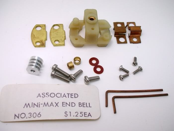
Here's the end bell kit with some extra goodies like the machine screws, comm cooler and buss bars:
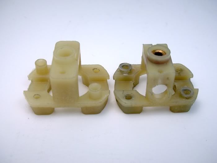
For some reason Associated spaced their brush hoods way father apart than the contemporary Mura B-motor


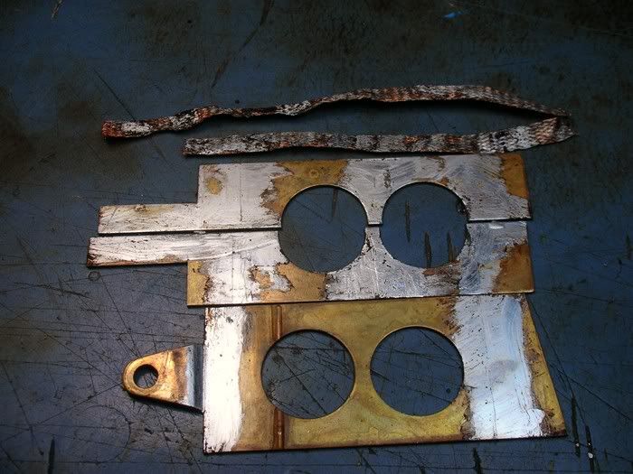
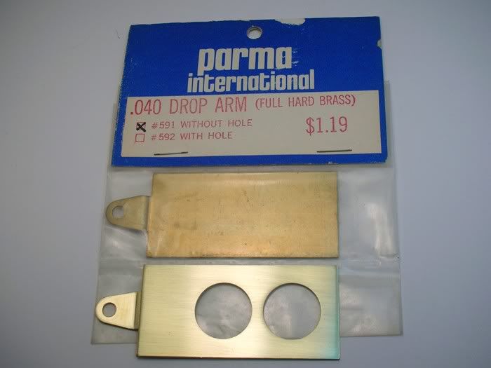
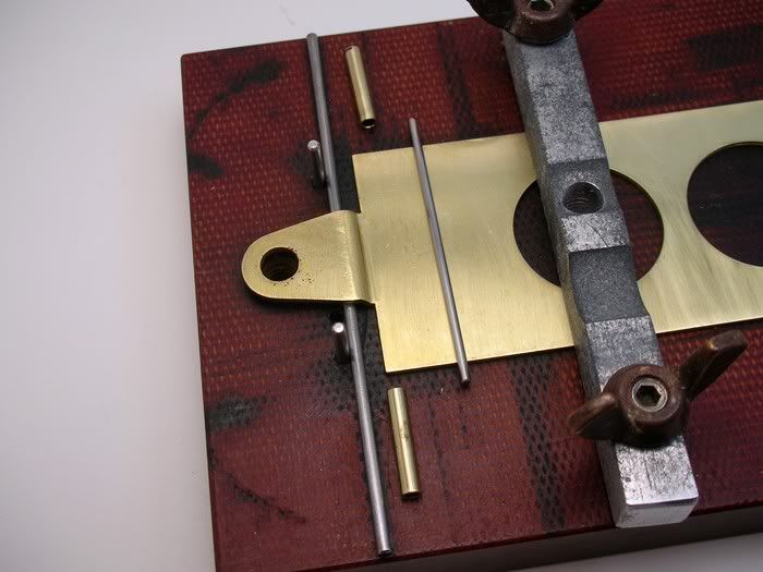
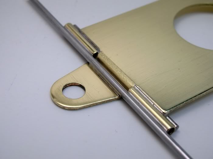
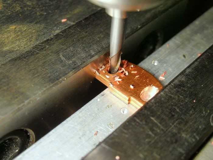
. I decided to use some thick copper B-motor super proofer brush plates and modify them. I elongated the original holes to fit the Associated end bell and better support the brushes:
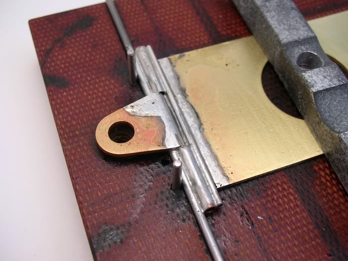
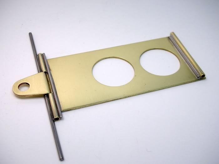
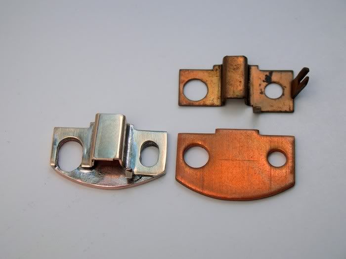
The brush hoods were notched out to move them in closer as well and soldered to the brush plates. Here a before and after:
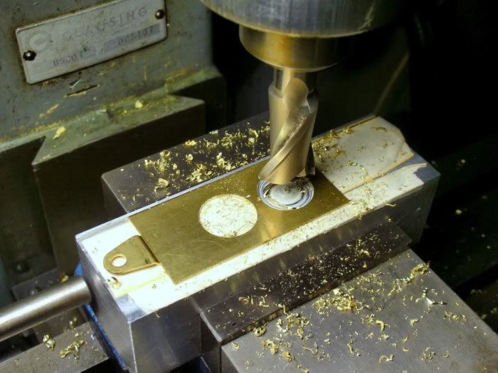
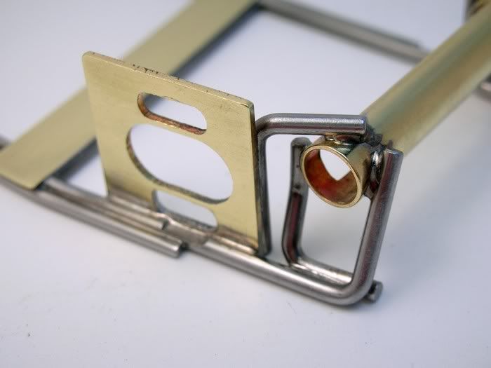
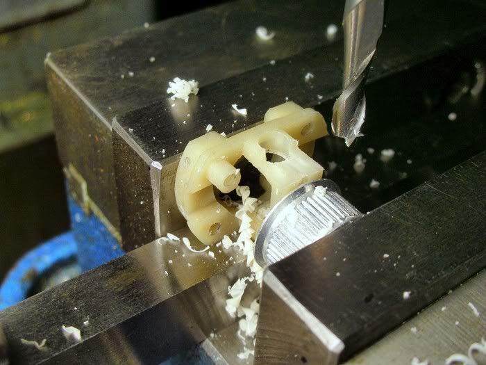
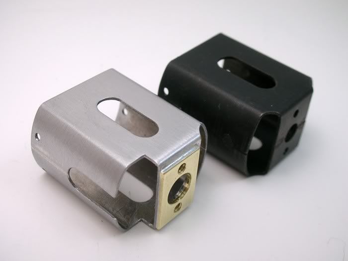
I used a period MRJ B-motor "hop up" article to further modify the motor. The end bell got notched for half rail clearance and holes for comm inspection:
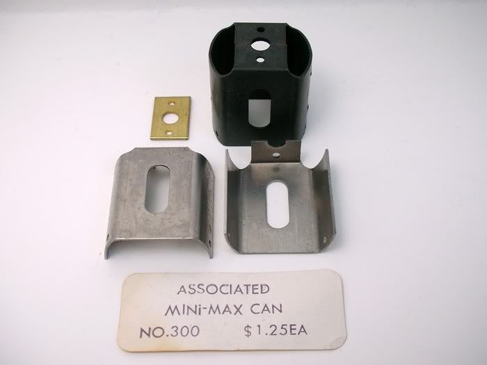
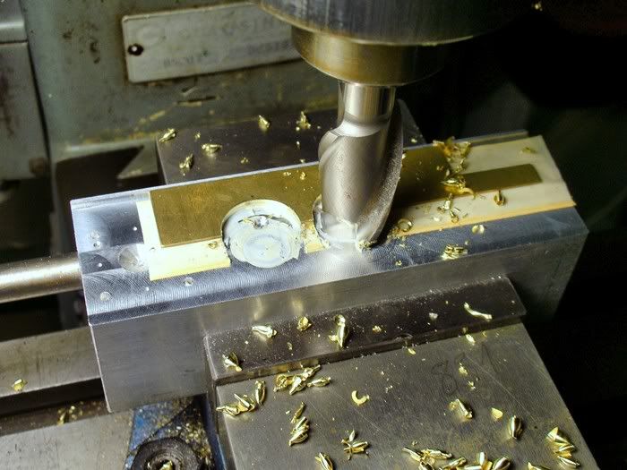
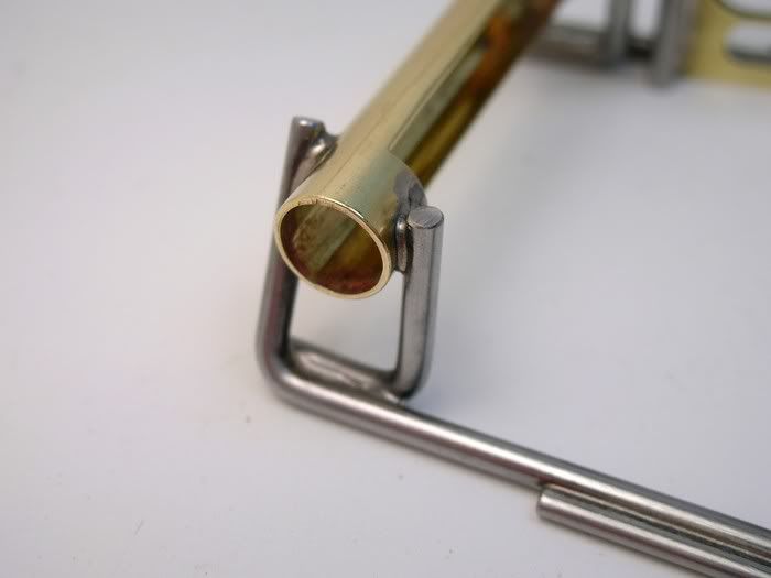
The can was soldered together and cut for axle clearance and narrowed at the bearing support. I also soldered that little brass plate included with the Associated kit onto the end bell to help hold the thing together. I'm not sure if that's what it's for but it seemed like a good idea at the time

.
The Blue Dot magnets needed some .010" shims to center them in the can and .004" shims to tighten up the air gap:
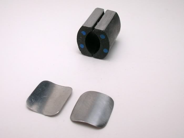
They slide nicely into the can and I installed the magnet springs and………..the can split apart at the solder joint

. I guess that's why Associated later offered the spot welded can

. I took the thing apart and applied a big honk'n mound of solder to the joints. I gooped up the top, bottom and back side of the magnets with JB Weld metal filled epoxy and installed them. When the epoxy cured I filed off the excess solder and now the epoxied in magnets are reinforcing the can.
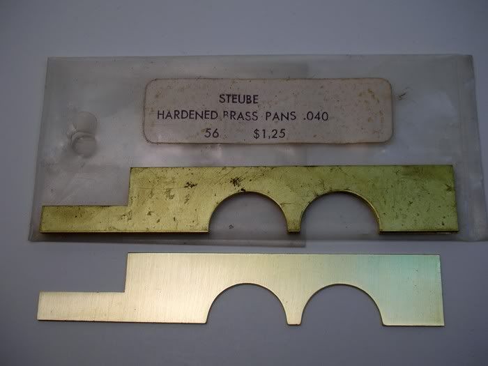
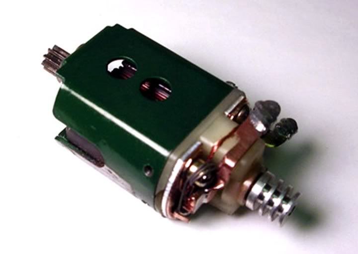
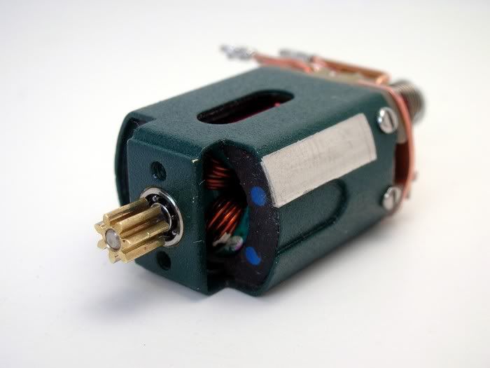
Here is the finished motor all painted up in a textured green finish in honor of the great Steube motors:
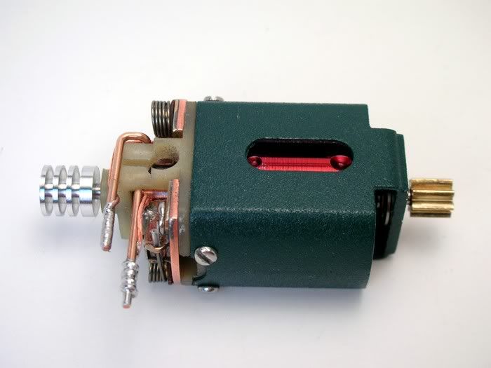
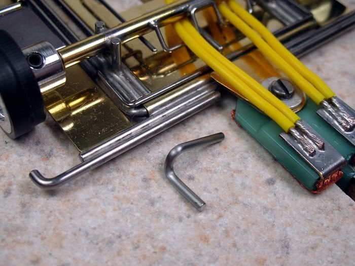
Neato old school buss bars, shunt wires and comm cooler:
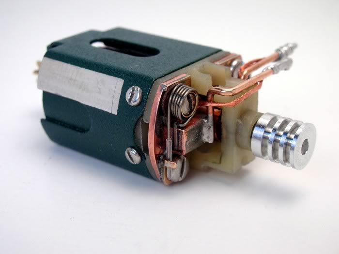
Yummy, blue dots and ball bearings:
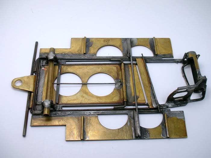
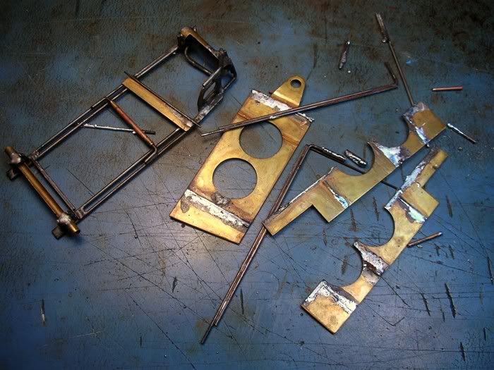
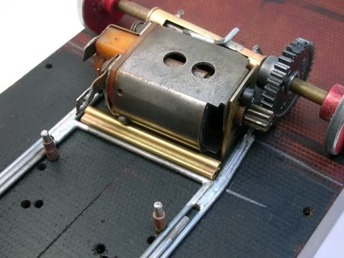
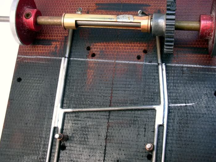
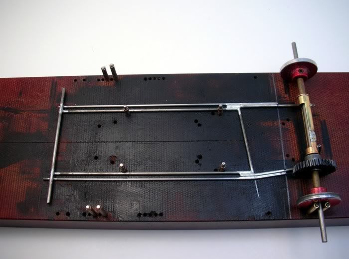
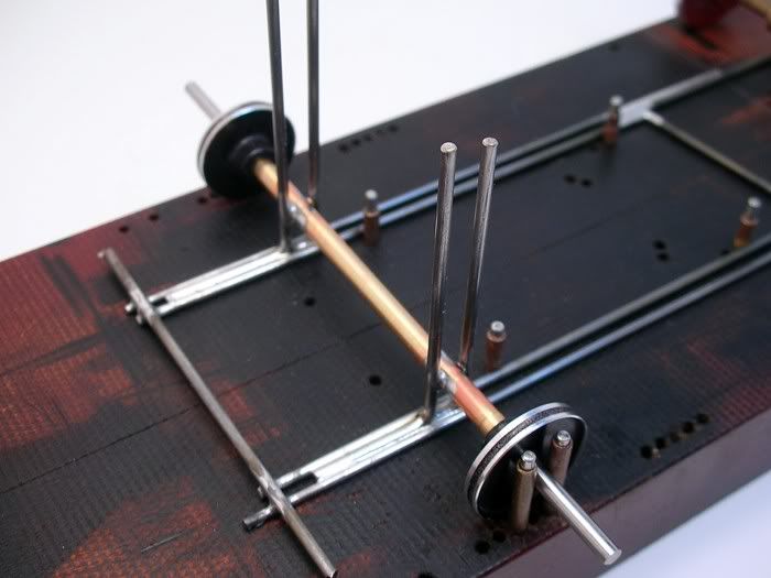
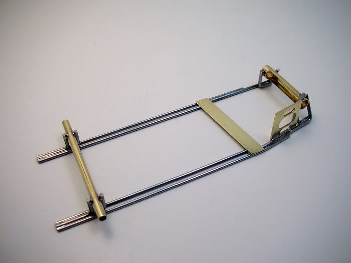
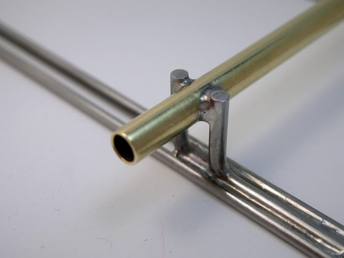
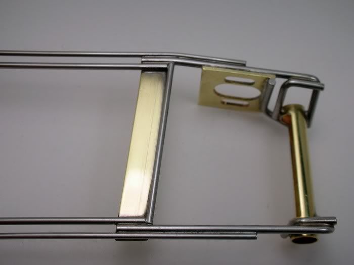
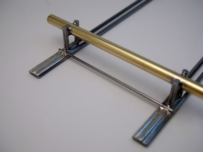
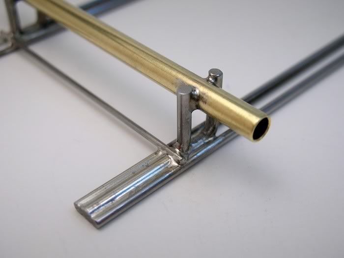
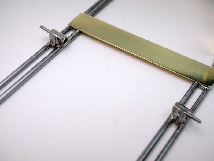
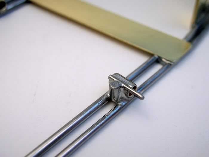
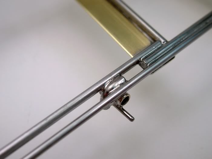
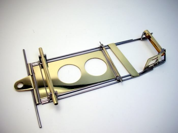
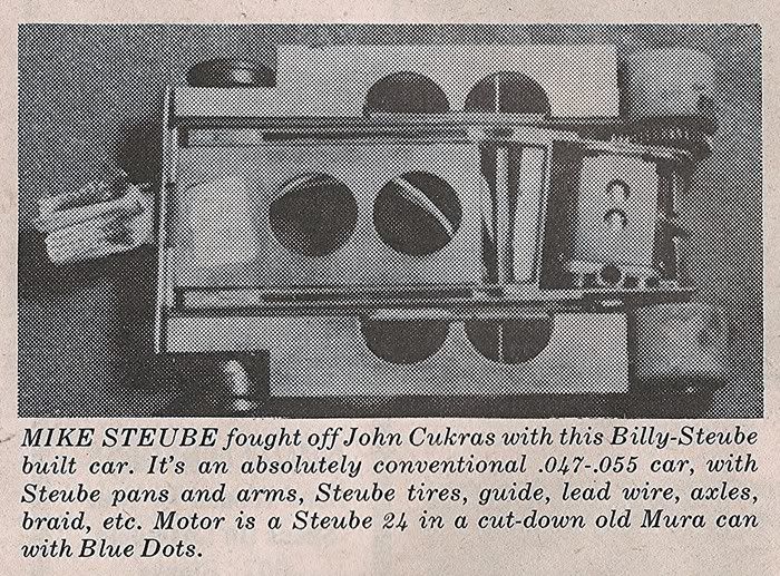
Next up a Billy Steube inspired chassis.
Onward


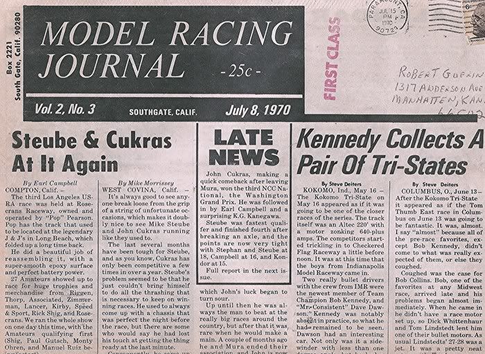
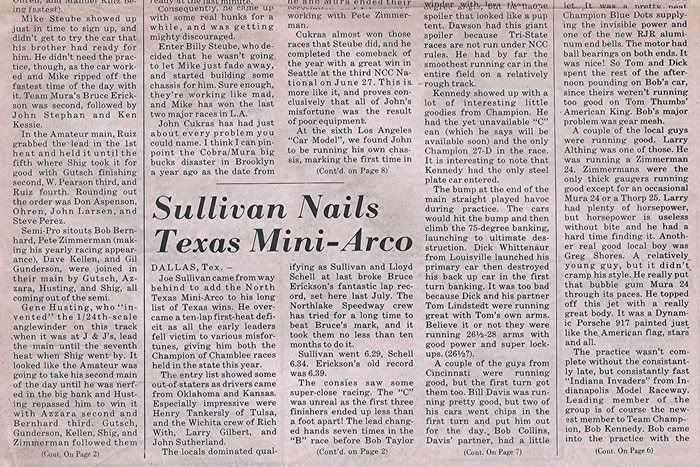
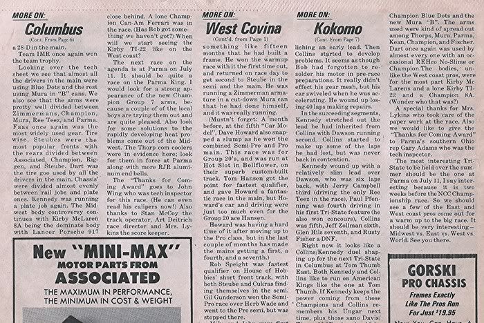
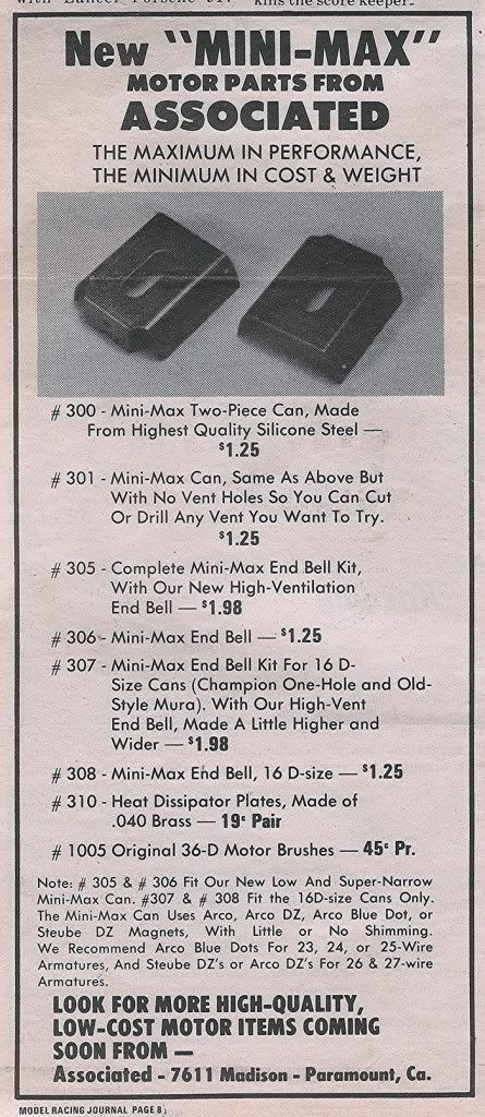
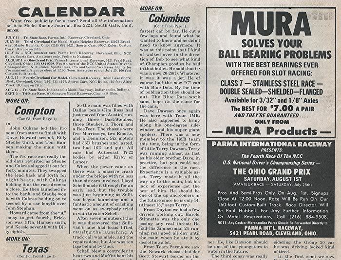
 . What did he use for a motor? Oh, they cut down a Mura 16D to the height of Arco Blue Dot magnets. A "pre C-can" low profile motor. Man, that's a lot of work. What's that Associated ad on the same page?