Jump to content


Photo

Commutator questions (with pics, of course!)


  • Please log in to reply
24 replies to this topic

#1 Edo

Edo

    The Kinkie Thingie Kingie

  • Full Member
  • PipPipPipPipPipPipPip
  • 2,181 posts
  • Joined: 16-February 06
  • Gender:Male
  • Location:Switzerland

Posted 03 October 2006 - 10:21 AM

Hi, gentlemen exps,
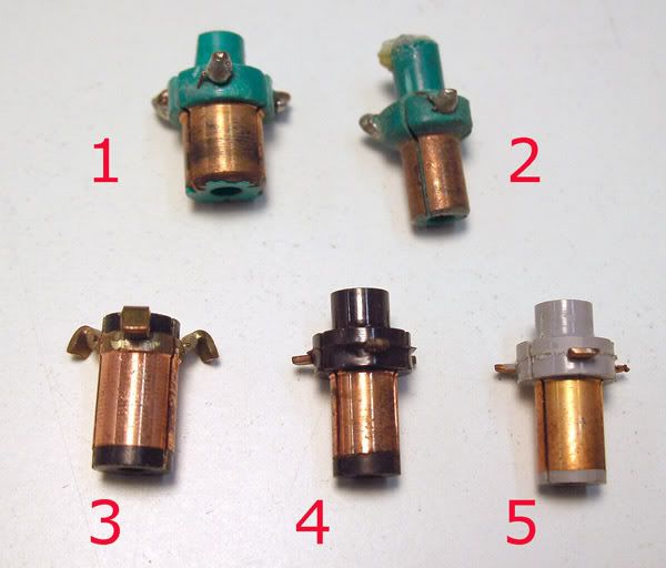
Here you can see 1 & 2 being the usual Mabuchi comms (the big one is for a 36D, n'est pas?)

Posted Image

Is no. 3 (possibly a LaGanke?) right for 16D motors? Or should I stick with 4 and 5?
In case it's OK for 16D use what would the advantage of having a thicker comm?

Here you see how the comm on the left has some distance from the top of the "web", instead the one on the left, which is flush with it and does look too close.

Posted Image

How do I set it up at the right distance?
I suppose I have to check if the brushes are aligned with it and then glue it?

Thank you for your attention,
Edo
EdoTBertoglio - Maverick assembler (formerly troubled)

Finish Line: the movie


#2 TSR

TSR

    The Dokktor is IN

  • Full Member
  • PipPipPipPipPipPipPipPip
  • 42,299 posts
  • Joined: 02-February 06
  • Gender:Male
  • Location:Marxifornia

Posted 03 October 2006 - 10:34 AM

Hi Edo,
The first green one is the factory unit for the Mabuchi FT36D. The second is for the FT16D. Both are actually good units for stock motors.
The third was marketed by quite a few companies and was produced by Kirkwood. It is the best to use. It generally needs a spacer before the stack. The fourth and fifth are Tradeship units, also pretty good for mild-power motors.

To space the comm properly, simply place the comm slightly away from the stack, then place a fiber washer behind the comm, then one thin brass washer on each side. Place the assembly in the empty can you will use for that arm, and install the end bell. When you press the end bell into the can, it will get you the exact needed armature length. Cut a fiber or metal spacer just the needed size and stick it behind the stack. In the case of the Tradeship comms, you may have to take some thickness off the back of the comm to fit, depending on your stack's length.
Use red hi-temp Loctite to set in place after you have determined the timing.
OK amigo?
:)

Philippe de Lespinay


#3 Edo

Edo

    The Kinkie Thingie Kingie

  • Full Member
  • PipPipPipPipPipPipPip
  • 2,181 posts
  • Joined: 16-February 06
  • Gender:Male
  • Location:Switzerland

Posted 03 October 2006 - 10:51 AM

Ok Dokk
I will follow your suggestions to the letter!
But now can you tell me what would be the advantage of having a thicker comm?
Thanks
Edo
EdoTBertoglio - Maverick assembler (formerly troubled)

Finish Line: the movie

#4 Ron Hershman

Ron Hershman

    Grand Champion Poster

  • Full Member
  • PipPipPipPipPipPipPipPip
  • 22,051 posts
  • Joined: 16-February 06
  • Gender:Male
  • Location:Indyanna

Posted 03 October 2006 - 01:09 PM

But now can you tell me what would be the advantage of having a thicker comm?

Thicker or bigger DIAMETER??????

#5 Edo

Edo

    The Kinkie Thingie Kingie

  • Full Member
  • PipPipPipPipPipPipPip
  • 2,181 posts
  • Joined: 16-February 06
  • Gender:Male
  • Location:Switzerland

Posted 03 October 2006 - 03:54 PM

Thicker or bigger DIAMETER??????

Gee, Ron, sorry for my iffy English. :lol:
I meant bigger DIAMETER commutator. I gather that a thicker one would allow for turning it down more often and have a new spotless surface everytime, non?
So what is the advantage of having a bigger DIAMETER com?
Thanks,
E.
EdoTBertoglio - Maverick assembler (formerly troubled)

Finish Line: the movie

#6 TSR

TSR

    The Dokktor is IN

  • Full Member
  • PipPipPipPipPipPipPipPip
  • 42,299 posts
  • Joined: 02-February 06
  • Gender:Male
  • Location:Marxifornia

Posted 03 October 2006 - 03:56 PM

More brush contact around less circumference. Good for more power as the brushes cannot "short out" while providing more contact surface area. :)

Philippe de Lespinay


#7 stevefzr

stevefzr

    Race Leader

  • Full Member
  • PipPipPipPipPip
  • 598 posts
  • Joined: 23-February 06
  • Gender:Male
  • Location:Melbourne, Australia

Posted 03 October 2006 - 08:25 PM

Edo,

If you're using long mags that you can't move around in the can, then I'd start by putting the arm blank in the can to work out where it wants to sit in the field. Then add spacers at the bottom (can end) of the arm and then follow the Doc's technique to find where the com should sit. Rememer to add your fibre washer and brass wash before pushing the endbell on. I only say this because I just wound a gorgeous looking 36D with silver wire and Kirkwood com, only to find I don't have enough adjustment with the Arco mags to get it centred in the field, which means it's constantly going to apply end thrust to the can bearing, and it won't get the most out of the magnetic field. :-(

Regards,

Stephen Corneille


#8 Ron Hershman

Ron Hershman

    Grand Champion Poster

  • Full Member
  • PipPipPipPipPipPipPipPip
  • 22,051 posts
  • Joined: 16-February 06
  • Gender:Male
  • Location:Indyanna

Posted 03 October 2006 - 10:28 PM

Thicker or bigger DIAMETER??????

Gee, Ron, sorry for my iffy English. :lol:
I meant bigger DIAMETER commutator. I gather that a thicker one would allow for turning it down more often and have a new spotless surface everytime, non?
So what is the advantage of having a bigger DIAMETER com?

If using the same size brush with different dia comms . . .

The smaller comm will run faster due to more "duration" of firing time. This also causes more "shorting" of the segments as the brush overlaps the segments more. In this scenario, the comm/arm will run warmer.

Most find that arms tend to get faster after more comm cuts, making the diameter smaller, and the brushes overlap the segements more and the "switch" effect causes the arm to fire quicker/earlier.

In group 7 racing, most run vertical-style brushes, as there is less over lap of the segments and the motors run cooler and are more reliable by doing this, especially in higher power applications. If you were racing open motors on low power, say 13.0 volts or lower, then the horizontal brushes may prove to be a advantage.

In the other "wing" classes, most use horizontal-style brushes as they run faster and the restricted group arms run cooler than open arms.

Most comms, no matter their overall diameter, have about .020" diameter give or take, to cut before hitting the plastic under the plates.

Most Kirkwood comms clean up/true at about .200" dia and they can be cut to .182" or so before hitting plastic.

The smaller Mabuchi/Parma 16D-type comms start at about .185" and can go to .170" or so in most cases.

#9 Cheater

Cheater

    Headmaster of the asylum

  • Root Admin
  • PipPipPipPipPipPipPipPip
  • 25,700 posts
  • Joined: 14-February 06
  • Gender:Male
  • Location:Norcross, GA

Posted 03 October 2006 - 10:35 PM

More brush contact around less circumference. Good for more power as the brushes cannot "short out" while providing more contact surface area. :)

P, I'm not certain that small versus large comm is quite so clear-cut as you infer.

A year or two ago, Paul Meiers in "Slot Car Bulletin" wrote a tech article about a Flexi with a 16D that was track-tested to establish a baseline lap time. Then the arm was removed, the comm was cut smaller, and reinstalled in the motor. After re-breaking-in the brushes, it was track tested again.

IIRC he cut the comm 2-3 times and every time the car got slighty faster. No conclusion was drawn as to why this occurred, but the effect seemed to be consistent: as the comm got smaller, the car turned faster laps.

It is my personal theory that the "shorting" of the brushes across adjacent comm segments is not always detrimental, but can actually be beneficial under specific conditions. My thinking is that the shorting assists in the collapse of the magnetic fields created by the energized coils of the armature poles.

Gregory Wells

Never forget that first place goes to the racer with the MOST laps, not the racer with the FASTEST lap


#10 gascarnut

gascarnut

    Posting Leader

  • Full Member
  • PipPipPipPipPipPipPip
  • 3,938 posts
  • Joined: 16-February 06
  • Gender:Male
  • Location:Irvine, CA

Posted 03 October 2006 - 11:58 PM

The frictional torque caused by the brush pressure decreases as the commutator gets smaller - that's another reason they run quicker than with big comms.
Dennis Samson
--------------------------
Scratchbuilding is life
Life is scratchbuilt

Samson Classics

#11 Ron Hershman

Ron Hershman

    Grand Champion Poster

  • Full Member
  • PipPipPipPipPipPipPipPip
  • 22,051 posts
  • Joined: 16-February 06
  • Gender:Male
  • Location:Indyanna

Posted 04 October 2006 - 07:58 AM

The frictional torque caused by the brush pressure decreases as the commutator gets smaller - that's another reason they run quicker than with big comms.

Maybe unless you increase spring tension . . .

As a brush gets shorter in length or the comm gets smaller in diameter, you need to increase brush tension to maintain the same "pressure" of the brush against the comm.

Less tension means less friction and more RPM, but also increases brush to comm arching causing more heat. You will also find less power at higher RPM due to brushes bouncing from the comm surface, increasing arching and heat. NOT GOOD!!!!!

#12 Hworth08

Hworth08

    Posting Leader

  • Member at Peace
  • PipPipPipPipPipPipPip
  • 3,563 posts
  • Joined: 16-February 06
  • Gender:Male
  • Location:Springfield, TN

Posted 04 October 2006 - 09:52 AM

Hard to make understandable but I remember a "debate" that started as whether the magnets were pushing or pulling the arm to make it rotate. The conversation did wind up with the agreement that when the comm "shorted", it reversed the field and caused both magnets to be working together during the brief period of overlap. That would support Greg's comment.
Don Hollingsworth
11/6/54-2/13/18
Requiescat in Pace

#13 Ron Hershman

Ron Hershman

    Grand Champion Poster

  • Full Member
  • PipPipPipPipPipPipPipPip
  • 22,051 posts
  • Joined: 16-February 06
  • Gender:Male
  • Location:Indyanna

Posted 04 October 2006 - 10:23 AM

In my personal opinion . . . if we are talking about radially-oriented magnets only. . .

The leading edge of rotation in regards to the armature should be strong while the exit tip should be weaker. RJR magnets/ motors were made opposite of this for years and I don't even want to go into all of the problems that created. Another reason most racers use Mura or Pro-Slot magnets in their motors.

The arm, depending on timing, usually fires or starts to switch on when the pole is just entering the tip area of a magnet and that is where you want the strongest field strength to be . . . again in my opinion. By the time the pole gets top dead center in the middle of the magnet, the rest is along for the ride onto the next magnet tip. You want the magnet to pull the arm into the field and then release or push it out. Most think the opposite.

The longer, taller, and thicker the leading magnet tip, the better/faster the motor will run. This will also allow you to run higher timing as well.
If I were to design a magnet, I would have a long leading tip and very little-to-no tip on the trailing edge/side of the magnet.

The more the magnet wraps around the armature, the better the motor runs.

The taller a magnet, the more timing you can run . . . the shorter the magnet, the less timing you can run.

#14 Cheater

Cheater

    Headmaster of the asylum

  • Root Admin
  • PipPipPipPipPipPipPipPip
  • 25,700 posts
  • Joined: 14-February 06
  • Gender:Male
  • Location:Norcross, GA

Posted 04 October 2006 - 10:36 AM

Commutation is a complicated subject and was extremely problematical in the early days of DC motors. For example, see this very informative link, which is mostly concerned with much larger DC motors than we use in slot racing:

http://www.reliance....v/motgen/c7090/

Regarding brush spring tension, my experience is that troublesome arcing at the comm generally occurs when spring tension is reduced below a critical point. And there seems to be very little benefit to increasing brush tension much beyond that point, except perhaps to add a small amount of brakes (though I haven't seen too many folks adjusting brush tension for that purpose). As I think I have commented before, almost everyone in the 1/24 arena uses the Champion light (red) springs for all non-strap motors, from soft 16Ds all the way up to hot X-12s, with good results. This suggests that the level of brush tension provided by the "3 o'clock" Champion springs is above the critical point, even for high-RPM 12s.

Don, while I am not particularly well-versed in electronics, I do know that when a coil of wire is connected to a current source, that "electrical current . . . creates a magnetic flux proportional to the current. A change in this current creates a change in magnetic flux that, in turn, generates an electromotive force (emf) that acts to oppose this change in current". In an automotive ignition coil (not the same kind of coil, of course), when the points open, this opposing emf can create a spark across the points that will eventually damage them unless it can be supressed. As most will know, in a coil and battery ignition system a capacitor is connected to the points to suppress the opposing emf by giving a place to go or to be absorbed. In a slot car motor, my thinking (probably flawed) is that the arc created by the brush shorting across adjacent comm segments may be caused by the opposing emf created as the coil is de-energized.

Over the years, I have noticed that after use, in most motors, black marks, of greater or lesser size, will appear on the comm sgements adjacent to the slots. I have also noticed that in most cases there will be little or no black marks on my best, i.e. fastest, motors, suggesting that little or no damaging arcing is occurring due to the happy coincidence of a number of related factors (timing, magnet strength, arm wind, etc.).

Gregory Wells

Never forget that first place goes to the racer with the MOST laps, not the racer with the FASTEST lap


#15 Ron Hershman

Ron Hershman

    Grand Champion Poster

  • Full Member
  • PipPipPipPipPipPipPipPip
  • 22,051 posts
  • Joined: 16-February 06
  • Gender:Male
  • Location:Indyanna

Posted 04 October 2006 - 11:26 AM

While I agree with most of what Greg just posted, I will add some more insight.

Red Champion springs do seem to work well in most applications in X-12 motors and the classes below that. I only tweak my springs for two reasons . . .one is to reduce arcing in unusually high-power, high glue situations with wing cars and the other is to increase brakes in scale cars.

My normal mode of operation when going to different tracks is to build all my motors with Champion red springs fiddle-sticked to make sure both side are the same tension. If I need more brakes, I change the spring to the Koford M-313 springs, which have a bit more tension, to increase brakes in scale cars or to reduce arcing in wing cars. There are times the Koford springs kill the top end of the motor; if that's the case, I tweak my Champion springs by bending the short leg from the 3 o'clock position to 4 o'clock position and that usually gives me the brakes without killing the top end.

When it comes to OPEN motors, Bob Green once told me you can never have too much spring tension and I tend to agree with that.

Another trick is to trim back (or make shorter) the brush tip on the side that makes the comm edge black. In most cases you will see no difference in performance, but will see a reduction in heat.

What you are looking for is a nice grey-colored thick brush "track" all the way around the comm surface where the brush rides. Once you have this, your tension is correct and when you have this nice thick grey-colored track, this helps to reduce oxidation of the comm surface where the brush rides and of the brush itself. If your track is mostly copper with spotty black tracks, you don't have enough tension. IF your track is all black and pitted . . . not enough tension or you are racing with a battery charger on. Increase tension to solve this problem.

Another tip: the copper area outside the brush track area should be a nice white gold color. If you have this, your tension and gearing are correct.

If the area outside the brush track is orange, you have a bit too much tension and the motor is running a tad warm. Sometimes a tooth bigger on the spur or a tooth smaller on the pinion with help.

If the area outside the track is red, too much tension and maybe under-geared.

If the area ouside the track is black, you have big problems..... LOL!

If the color is gold to white gold, all is good.

Man, did this get off-topic from the original post of comm diameters..... :lol:

#16 Cheater

Cheater

    Headmaster of the asylum

  • Root Admin
  • PipPipPipPipPipPipPipPip
  • 25,700 posts
  • Joined: 14-February 06
  • Gender:Male
  • Location:Norcross, GA

Posted 04 October 2006 - 11:50 AM

I agree with most of what Greg just posted:

That's nice to hear, for I bet you have built probably a thousand times more motors than have I.

Ron, your insight on placement of the stronger magnet tips is indeed opposite from what I've heard and practiced. Time for me to do some more testing!

Man, did this get off-topic from the original post of comm diameters..... :lol:
True, but I don't have a problem with this kind of thread drift. Info of this quality isn't found on most of the other slot forums, either because the members don't have the knowledge or because they're unwilling to share it.

It's threads like this that make Slotblog a special place in my view, in spite of some who want to disparage the forum's currently-small membership numbers.

Gregory Wells

Never forget that first place goes to the racer with the MOST laps, not the racer with the FASTEST lap


#17 Hworth08

Hworth08

    Posting Leader

  • Member at Peace
  • PipPipPipPipPipPipPip
  • 3,563 posts
  • Joined: 16-February 06
  • Gender:Male
  • Location:Springfield, TN

Posted 04 October 2006 - 12:52 PM

Thread drift? Everything discussed has been about commutators and their relation to magnets. nd it has been a 303 class! :)

OK, if I'm reading this right, Ron builds his motor with stronger leading edges. Would that support the theroy of "pulling" the arm?

I've heard/read that the electricity going through the wire is travelling at the speed of light. Wonder if that is correct? Believe that a Group 12 motor averages about a 150,000 RPM while on the track. That would equate to the comm opening and closing 7,500 times per second. Does ALL the "used" electricity get pushed out in 1 revolution or does some "old" electricity take up room? Does anyone KNOW? :lol:

Thanks for the good info. Now I know how to read a comm!
Don Hollingsworth
11/6/54-2/13/18
Requiescat in Pace

#18 Horsepower

Horsepower

    **Numb Thumbs**

  • Full Member
  • PipPipPipPipPipPipPip
  • 4,343 posts
  • Joined: 16-February 06
  • Gender:Male
  • Location:Chicago

Posted 04 October 2006 - 01:14 PM

Edo- For what it's worth at this point, number 5 (gray) is a Tradeship. It has 11 degrees timing advance built in. I have a small box of these. :)
Gary Stelter
 
My life fades, the vison dims. All that remains are memories... from The Road Warrior

#19 Edo

Edo

    The Kinkie Thingie Kingie

  • Full Member
  • PipPipPipPipPipPipPip
  • 2,181 posts
  • Joined: 16-February 06
  • Gender:Male
  • Location:Switzerland

Posted 04 October 2006 - 01:16 PM

Thanks Gary! Nice to see you here!

Man, did this get off-topic from the original post of comm diameters..

Not really! And we're enjoying it very much, gentlemen!
Since you're on a roll here may ask a few more pertinent questions?
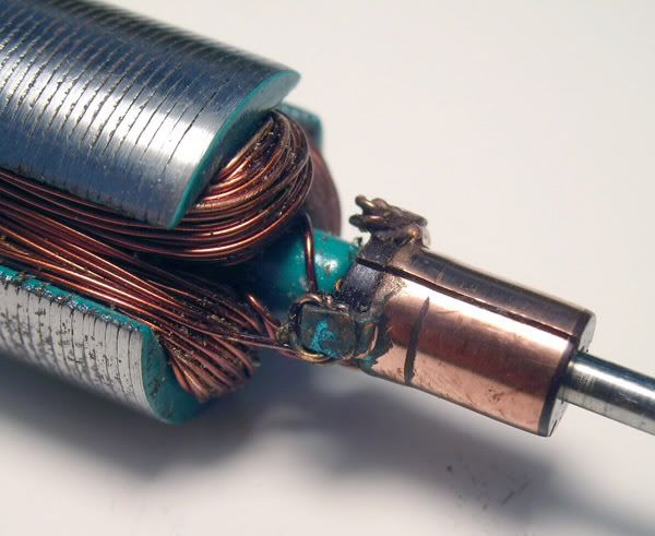
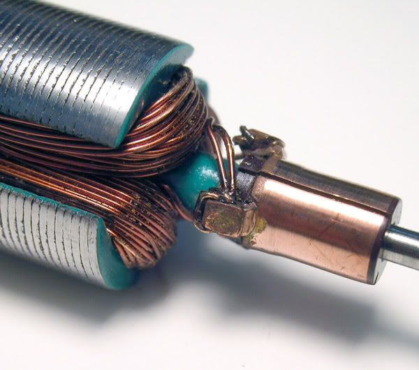
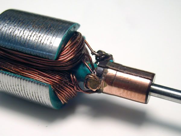
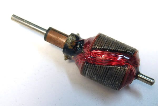
Do you exps find this arm has been proprely rewound?
It looks funny to me, but then what do I know?

Posted Image
Posted Image
Posted Image

It actually shows about .359 Milliohms on the 3 segments so it should work fine, non?

Now how about this one:

Posted Image

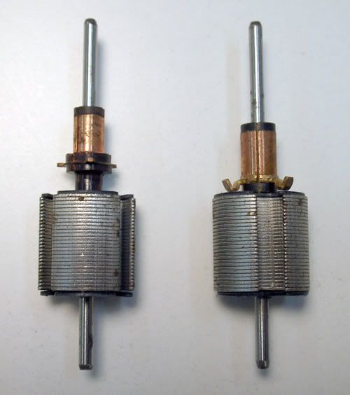
What is the theory behind this kind of funny stack set up?
Thanks again for your answers
Edo
EdoTBertoglio - Maverick assembler (formerly troubled)

Finish Line: the movie

#20 Ron Hershman

Ron Hershman

    Grand Champion Poster

  • Full Member
  • PipPipPipPipPipPipPipPip
  • 22,051 posts
  • Joined: 16-February 06
  • Gender:Male
  • Location:Indyanna

Posted 04 October 2006 - 02:27 PM

Edo,

The top three pics, it's hard to tell if it's a single or a double wind with all the wire wrapped around the comm tang.

While I wouldn't give you a A+ for appearance ;) I would give you a A+ if all three poles have the same resistance number. That is very good.

The most important thing about hand winds is that you layer the first two rows of wire nice and straight on each pole. The rest of the windings are along for the ride after that.

Yes, Group 27 and 7 arms are very nice and neat and that helps the epoxy keep all the wires attached to one another and to the blank. Remember those are turning 150,000 RPM's and more.

The bottom pic is a arm using a "skewed" blank similar to train motors. Skewed arms run more efficient compared to straight blanks and run slower, but are more reliable and run cooler.

#21 Prof. Fate

Prof. Fate

    a dearly-missed departed member

  • Member at Peace
  • PipPipPipPipPipPipPipPip
  • 6,580 posts
  • Joined: 20-February 06
  • Gender:Male
  • Location:Salt Lake City, UT

Posted 05 October 2006 - 10:36 AM

Hi,

The skewed stack was developed by the train guys before slots were a fad, really. One thing the train guys want is a "realistic" easing away from stationary into smooth delivery of power. These days, the train guys use pulse power with cheaper, more ordinary motors to get the same effect.

However, in about '64 or so a lot of us observed, pre-cans, that the skewing on our Pittmans and so on often produced a very smooth power delievery. Remember, this was when our "best" controller was things like the MRRC "pot". Getting a resistor to match your motor was difficult. And as most had several cars in several classes, most of us building motors tried a skewed stack in an effort to make the car more driveable with the controller resistors we had. A failed dead-end, but most of us tried it.

This is from the same period where we were doing 5 and 7 pole, star winds, and all sorts of things to experiment with solving various real and imagined problems.

Fate
Rocky Russo
3/6/48-1/1/12
Requiescat in Pace

#22 Cheater

Cheater

    Headmaster of the asylum

  • Root Admin
  • PipPipPipPipPipPipPipPip
  • 25,700 posts
  • Joined: 14-February 06
  • Gender:Male
  • Location:Norcross, GA

Posted 05 October 2006 - 11:13 AM

OK, if I'm reading this right, Ron builds his motor with stronger leading edges. Would that support the theory of "pulling" the arm?

I'll let Ron speak to this, as I am so confused now that my opinion is being revised!

I've heard/read that the electricity going through the wire is travelling at the speed of light. Wonder if that is correct? Believe that a Group 12 motor averages about a 150,000 RPM while on the track. That would equate to the comm opening and closing 7,500 times per second. Does ALL the "used" electricity get pushed out in 1 revolution or does some "old" electricity take up room? Does anyone KNOW?

Electricity does travel down wire at nearly the speed of light, Don, but how quickly the current in a coil dissipates depends on the coil's inductance, as I understand it. Inductance is a property I know so little about that I won't pretend to be able to explain it, but let me just say that when the current connected to the coil is removed, it takes a small but finite amount of time for the coil to "uncharge". Perhaps someone else can address this.

BTW, I don't think a Group 12 motor will turn quite that high an RPM. I'm guessing more like 80-90,000 rpm.

Now I know how to read a comm!

Yes, that's great info regarding comm reading. Thanks, Ron!

Gregory Wells

Never forget that first place goes to the racer with the MOST laps, not the racer with the FASTEST lap


#23 Hworth08

Hworth08

    Posting Leader

  • Member at Peace
  • PipPipPipPipPipPipPip
  • 3,563 posts
  • Joined: 16-February 06
  • Gender:Male
  • Location:Springfield, TN

Posted 05 October 2006 - 12:09 PM

Well, I was afraid the contributors here didn't have the equiment to measure the speed of electicity so I asked Mr. Google. Electricity CAN NOT travel at the speed of light because electricity is an electron and has mass. Light is a proton and does NOT have mass or as we would say here, light don't weight nothin'.

Using a particle acclerator, 1 electron can almost be pushed to the speed light.

Ron mentioned duration in one of his post that started me thinking about a racing engine that does have an amount of "used" fuel left in the cylinder from the previous firing or actually the previous 10 or so. I learned that an electric motor does not "burn" electrons but only slows them down. In therory a person shouln't owe an electric bill, you return as many electrons as you buy. What you actually buy are a stream of "flowing" electrons. If the electrons aren't flowing, they are just static electricity.

Guess some of you didn't know all this and many others I'm sure don't care! :) I'll have to look futher for a break-through in slot car motors
Don Hollingsworth
11/6/54-2/13/18
Requiescat in Pace

#24 Ron Hershman

Ron Hershman

    Grand Champion Poster

  • Full Member
  • PipPipPipPipPipPipPipPip
  • 22,051 posts
  • Joined: 16-February 06
  • Gender:Male
  • Location:Indyanna

Posted 05 October 2006 - 12:29 PM

OK, if I'm reading this right, Ron builds his motor with stronger leading edges. Would that support the theory of "pulling" the arm?

I'll let Ron speak to this, as I am so confused now that my opinion is being revised!

I've heard/read that the electricity going through the wire is travelling at the speed of light. Wonder if that is correct? Believe that a Group 12 motor averages about a 150,000 RPM while on the track. That would equate to the comm opening and closing 7,500 times per second. Does ALL the "used" electricity get pushed out in 1 revolution or does some "old" electricity take up room? Does anyone KNOW?

Electricity does travel down wire at nearly the speed of light, Don, but how quickly the current in a coil dissipates depends on the coil's inductance, as I understand it. Inductance is a property I know so little about that I won't pretend to be able to explain it, but let me just say that when the current connected to the coil is removed, it takes a small but finite amount of time for the coil to "uncharge". Perhaps someone else can address this.

BTW, I don't think a Group 12 motor will turn quite that high an RPM. I'm guessing more like 80-90,000 rpm.

Hey, I don't know if my magnets are pulling or pushing . . . all I know is that when my arm fires/charges with 38 to 45 degrees of timing, the leading tip of the pole is just entering the tip of the magnet at the time of firing . . . this is where I want my magnet to be strong, not in the center or the trailing tip as all firing/charging is well done by this point.

Engineers who make lots of money and have been well eductated will usually tell you that there is no way our motors should work they way they do. You should have seen the look on the engineers face the day he went to the track with me and hooked his oscilloscope to the track. I told him the motor would surge 125 amps or so when taking off and continue to pull 40 amps or so while running laps before he ever went to the track. He told me no way. All I heard him say when I punched the car, looking at the scope was: Oh My God . . . LMAO. He told me a three-pole arm wound with 16 turns of 24 gauge wire was nothing more than a direct short. The engineers have not figured it out yet.

Check this out . . .

Where do any of you think the magnet should be its strongest upon initial firing??? Print that pic out and take a close look where things are located when the firing begins.

Group 12 motors turn about 50,000 to 60,000 RPMs.

Homeset motors are way over-rated when it comes to RPM ratings these days.

Besides there is really no accurate way to measure or even dyno DC motors. RC motors are all over the dyno when doing back to back to back dyno test runs even when allowing them to cool down to the same temp for every test run. Rev testing on a power suppy doesn't cut it either. I have had some pretty sad-sounding motors on the power pack turn out to be the fastest thing on the track. Like I said . . . put it in the car and try it before benching it.

The only way to know how a motor is going to perform, is to put it into your car and run it!!! There is no substitute.

As for further "break throughs" in slot motors . . . this will only come from changes in materials used and design mods. The rest is basic stuff that has worked for years and will never change.

#25 Hworth08

Hworth08

    Posting Leader

  • Member at Peace
  • PipPipPipPipPipPipPip
  • 3,563 posts
  • Joined: 16-February 06
  • Gender:Male
  • Location:Springfield, TN

Posted 05 October 2006 - 01:48 PM

My first thought after looking at the timing chart was to tell Edo those are all old commutators and be done with this thread! :) That chart answers little but creates a LOT of questions. We know the fastest motor have 35 to 45 degree timing depending on the track layout, magnets, and power supply. By the chart that's when the stack is leaving the magnet tip and the comm segment is about to short out. Lot to sort out!

125 amps, 8 cars after a track call, 1000 amps! Pretty much beyond what Revell and Monogram envisioned slots becoming! :)
Don Hollingsworth
11/6/54-2/13/18
Requiescat in Pace


Electric Dreams Online Shop