

Hello-
I am interested in building a chassis for a Wing car - scratchbuilt, with piano wire and small brass pieces. Although I have looked and searched I have not found much info( except for many pictures I can use for reference).
I was wondering if there are also drawing plans (like there are some for Retro chassis) and the measurement/dimensions requirements/rules, measurements for placing/attaching the body pins, front wheels (I'll use tiny wheels, just don't like the fake wheels), etc.
I have the body, a Koford motor, and all the other parts, so wanted to build this car for fun and experiment with Wing cars (I am mostly into Retro and scale cars). I am not expecting to win any races with this chassis project since it would probably not compete with the technology of laser cut wing chassis out there now, but I'd like to try something anyway.
Thanks for any info.
racer g

Need info: drawings/plans for Wing car chassis
Started by
racer g
, Apr 27 2011 10:52 AM
24 replies to this topic
#1

racer g
-
- Full Member
-

- 47 posts Joined: 24-July 08
Rookie Keyboard Racer
- Location:NY
Posted 27 April 2011 - 10:52 AM
Gus Remor
#2
Rotorranch
-

- Full Member
-
- 1,755 posts Joined: 22-November 10
What's a title?
- Gender:Male
- Location:Atlanta, GA
Posted 27 April 2011 - 11:05 AM
Do any Wing car classes even allow scratchbuilt chassis any more, except open (GP7) class?
Rotor
Rotor
Jeff Chambers

"Kinky Kar"
"Kinky Kar"
#3
Rotorranch
-
- Full Member
-
- 1,755 posts Joined: 22-November 10
What's a title?
- Gender:Male
- Location:Atlanta, GA
Posted 27 April 2011 - 11:08 AM
I know somewhere there is a thread for a vintage late '70s style steel Wing car chassis. It came out of a magazine. Someone here posted it a couple months ago, but I can't find it now.
I actually built several of them from a carpenter saw blade in the late '70s, (as well as a few of my own design) and I still have the template here somewhere.
I later used pre-cut centers to build from. Pacesetter maybe?
Rotor
I actually built several of them from a carpenter saw blade in the late '70s, (as well as a few of my own design) and I still have the template here somewhere.
I later used pre-cut centers to build from. Pacesetter maybe?
Rotor
Jeff Chambers
"Kinky Kar"
"Kinky Kar"
#4
Ron Hershman
-

- Full Member
-
- 22,051 posts Joined: 16-February 06
Grand Champion Poster
- Gender:Male
- Location:Indyanna
Posted 27 April 2011 - 11:32 AM
I think you can run "scratchbuilt" chassis in all USRA Wing classes EXCEPT Spec 15 and Boxstock.Do any Wing car classes even allow scratchbuilt chassis any more, except open (GP7) class?

#5
Rotorranch
-
- Full Member
-
- 1,755 posts Joined: 22-November 10
What's a title?
- Gender:Male
- Location:Atlanta, GA
Posted 27 April 2011 - 11:50 AM
Ron, I just checked the 2010 USRA rule book. Spec 15, GP12, and GP27L must use commercially-available chassis. I15, C12/15, GP27, and GP7 have no chassis restrictions.
Rotor
Rotor
Jeff Chambers
"Kinky Kar"
"Kinky Kar"
#6
Bill from NH
-

- Full Member
-
- 14,778 posts Joined: 02-August 07
Age scrubs away speed!
- Gender:Male
- Location:New Boston, NH
Posted 27 April 2011 - 12:47 PM
Gus,
I don't recall ever seeing any published plans, but it wouldn't be too hard to draw your own custom plans. Build to the standard 3-1/4" width and 1/16" clearance. The distance from the rear axle to the guide post could be varied as could be the wheelbase. The center sections and the pan areas could brass, steel, open, or a combination of any of them.
What do you have planned for a body and motor? I've often thought of building a similar project using an O/S Corvette or Viper body with a modern arm in one of my C-can setups from the '70s.
Bill Fernald
I intend to live forever! So far, so good.
I intend to live forever! So far, so good.
#7
Cheater
-

- Root Admin
-
- 25,700 posts Joined: 14-February 06
Headmaster of the asylum
- Gender:Male
- Location:Norcross, GA
Posted 27 April 2011 - 12:55 PM
Gregory Wells
Never forget that first place goes to the racer with the MOST laps, not the racer with the FASTEST lap
#8
Craig
-

- Member at Peace
-
- 1,691 posts Joined: 13-March 08
Checkered Flag in Hand
- Gender:Male
- Location:S Lake Tahoe, CA
Posted 27 April 2011 - 02:15 PM
Hey Gus,
I can produce an AutoCAD drawing for you at a nominal fee. Simple let me know what you want and I can draw something up for you.
I can produce an AutoCAD drawing for you at a nominal fee. Simple let me know what you want and I can draw something up for you.
Craig Correia
11/27/57-8/12/22
Requiescat in Pace
11/27/57-8/12/22
Requiescat in Pace
#9
Ron Hershman
-
- Full Member
-
- 22,051 posts Joined: 16-February 06
Grand Champion Poster
- Gender:Male
- Location:Indyanna
Posted 27 April 2011 - 03:02 PM
Ron, I just checked the 2010 USRA rule book. Spec 15, GP12, and GP27L must use commercially-available chassis. I15, C12/15, GP27, and GP7 have no chassis restrictions.
Rotor
Yea I forgot about that new fangled 27L class....LOL
#10
Hworth08
-

- Member at Peace
-
- 3,563 posts Joined: 16-February 06
Posting Leader
- Gender:Male
- Location:Springfield, TN
Posted 27 April 2011 - 03:15 PM
Who was the Wing racer from Texas that I believe passed away? He might have been the best with home-made piano wire Wing frames.
Maybe he posted some info? Seems like he might have worked with Slick 7.
Maybe he posted some info? Seems like he might have worked with Slick 7.
Don Hollingsworth
11/6/54-2/13/18
Requiescat in Pace
11/6/54-2/13/18
Requiescat in Pace
#11
Ron Hershman
-
- Full Member
-
- 22,051 posts Joined: 16-February 06
Grand Champion Poster
- Gender:Male
- Location:Indyanna
Posted 27 April 2011 - 04:13 PM
Craig Landry.
Wire chassis became un competitive many years ago....... if they were competitive.... they would be used today.... everyone uses aluminum chassis these days and have been for years. Unless class rules specify differently.
Craig's business before he passed away was aluminum and steel chassis..... he was pretty much out of the wire chassis business at that point.
#12
racer g
-
- Full Member
-
- 47 posts Joined: 24-July 08
Rookie Keyboard Racer
- Location:NY
Posted 27 April 2011 - 05:27 PM
thanks for the replies, guys, and the link to the 2011 rule book is great,I got some more new info in there, but it still does not specify overall dimensions for the location of the parts...(unless I missed it's listed in a different page..?..)
As I mention in the beginning, this chassis project is not intended for competive racing(I totally agree with Ron H) - I basically want to build a wingcar with some parts I have available, and take it to the track for testing and run laps, as I have never really been into wing cars before, I want to see if I can 'feel' the difference in driving a slot car where downforce and aerodynamics can come effectivelly into play with the super light "hardware" and aero/diaplane body. to most of you here these(my) questions must sound naive, but one needs to start somewhere...
---------------------------
Bill from NH. -thanks- that's what I need for starters:
- width 3 1/4" ;
-1 1/16 clearance
-*still need a reference for body pin mounts distance from the rear axle
-*wheelbase measurement from rear axle
-*height measurement for the rear axle
-- can I make the guide lead same as a champion or parma flexi type for reference?
,*** the motor is a Koford with x-12+ arm, and I'll post picture of the body once I can get the chassis project started(I'm notsure what body it is...sorry)
----------------------------------------
Rotor,
do you have pictures of your builts from saw blade?you mean like a wood saw blade? never thought of that as a source for steel - I like that idea... I wonder if that's what Tony P and PdL 'the doctor' used as source for material on the first steel/brass/wire chassis that they built , which I've seen in the old slot car magazine articles - was it difficult to cut the steel?(dremmel?)
-----------------------------------------
the saga continues...
racer g
Gus Remor
#13
Rotorranch
-
- Full Member
-
- 1,755 posts Joined: 22-November 10
What's a title?
- Gender:Male
- Location:Atlanta, GA
Posted 27 April 2011 - 06:51 PM
Racer G... I still have most of the chassis. I built a few for other racers, including the track owners wife, that I don't have, but I do still own most of them. They are in a box somewhere around here, pickled in oil in baggies. I'll have to dig them up and take pics.
Yes, I used a Dremel, or an air powered die grinder with a Carborundum cutoff wheel to cut them. And yes, a carpenters wood hand saw blade is what I used. Here's what's left of one of them.

It's .037in, last used for hard body Indy car chassis in the 90's. I used different thicknesses for different chassis.
Rotor
Yes, I used a Dremel, or an air powered die grinder with a Carborundum cutoff wheel to cut them. And yes, a carpenters wood hand saw blade is what I used. Here's what's left of one of them.
It's .037in, last used for hard body Indy car chassis in the 90's. I used different thicknesses for different chassis.
Rotor
Jeff Chambers
"Kinky Kar"
"Kinky Kar"
#14
Bill from NH
-
- Full Member
-
- 14,778 posts Joined: 02-August 07
Age scrubs away speed!
- Gender:Male
- Location:New Boston, NH
Posted 27 April 2011 - 08:07 PM
-*still need a reference for body pin mounts distance from the rear axle
I never saw a rule that specified pin locations. It could be anywhere along a chassis's side, depending on the body being used & your chassis construction. I prefer one pin location not too far in front of the rear wheels & a 2nd behind the front wheels. Years ago, I positioned them beside the pan's hinge wires, using the wires as tubing reinforcement.
-*wheelbase measurement from rear axle
That would really depend on your track layout. The retro racers in D3/IRRA will usually start with a 4" wheelbase. If you're going to run on a king or other high speed track with lots of banking, try someting shorter, perhaps as short as 3 3/4". But it'll be mostly trial & error on your part.
-*height measurement for the rear axle
This will depend on the diameter of the rear tires you plan on using. Take half the tire size & subtract 1/16" from it. That will be the height your rear axle needs to be in order to provide 1/16" chassis clearance.
Do you have a chassis jig & jig wheels to use while constructing your chassis? If not, I'd recommend you have both. They'll make your building much easier. It would be okay to use a turbo-flex to set various part locations & distances. Rotor's hand saw blade as a supply for sheet steel is a good one. Cabinet scrapers & wide sheetrock knives are a couple other sources. Personally, I find cutting sheet steel cars a PIA, so I avoid it, when possible.
Bill Fernald
I intend to live forever! So far, so good.
I intend to live forever! So far, so good.
#15
Bill from NH
-
- Full Member
-
- 14,778 posts Joined: 02-August 07
Age scrubs away speed!
- Gender:Male
- Location:New Boston, NH
Posted 27 April 2011 - 08:49 PM
Gus, here's the link to a MN wing car with scratchbuilt chassis built about 2004. It's just one person's idea how to proceed.
click here
click here
Bill Fernald
I intend to live forever! So far, so good.
I intend to live forever! So far, so good.
#16
Hworth08
-
- Member at Peace
-
- 3,563 posts Joined: 16-February 06
Posting Leader
- Gender:Male
- Location:Springfield, TN
Posted 27 April 2011 - 11:58 PM
ebay often has a piano wire framed Wing car. They usually sell pretty cheap or you can get ideas from the pictures.
If it's a G-12 old car the motor might be 60 turns of 29, a fair amount slower than today's 55/29.
If it's a G-12 old car the motor might be 60 turns of 29, a fair amount slower than today's 55/29.
Don Hollingsworth
11/6/54-2/13/18
Requiescat in Pace
11/6/54-2/13/18
Requiescat in Pace
#17
Rotorranch
-
- Full Member
-
- 1,755 posts Joined: 22-November 10
What's a title?
- Gender:Male
- Location:Atlanta, GA
Posted 28 April 2011 - 01:27 AM
Craig Landry.
Wire chassis became un competitive many years ago....... if they were competitive.... they would be used today.... everyone uses aluminum chassis these days and have been for years. Unless class rules specify differently.
Craig's business before he passed away was aluminum and steel chassis..... he was pretty much out of the wire chassis business at that point.
Ron, we had a few guys running Craig's Zap wire 12's at my shop competitively on the King. They also worked well on the Kingleman.
I sold quite a few of them. A few guys liked them better than the steel cars.
Rotor
Jeff Chambers
"Kinky Kar"
"Kinky Kar"
#18
qtupro
-

- Full Member
-
- 110 posts Joined: 21-May 07
Mid-Pack Racer
- Gender:Male
- Location:WI
Posted 28 April 2011 - 07:34 AM
I would look at the car lengths in some manufactures catalog. They come in at anywhere from 4.250 long and up. The shorter the car the faster it will be in the turns. The longer the car the more forgiving.Unless you are running on a modern king I would build longer about 4.500. Mount your front pin tubes as far forward as you can. That will give you more front down force.
#19
racer g
-
- Full Member
-
- 47 posts Joined: 24-July 08
Rookie Keyboard Racer
- Location:NY
Posted 29 April 2011 - 01:37 PM
Alright, thanks for all the info and tips, guys. Very much appreciated.
Going ahead with the project, this is what I came up for a plan. (i found a picture on epay where the seller placed a ruller next to a wing car chassis so I was able to estimate the size of the motor box and frame - then I applied to my own design -the rough drawing seen to the right of the mock-up - you'll noticed I changed the size of the front brass piece to go all across the width of the chassis and the overall design changed a little after some more 'contemplation"...
1-The first picture shows a quick mock-up of the main cut brass and rails( I will cut up the 2 rails from the motor box where they meet the center rail and solder all three pieces. The front part of the center rail will fit -but not rattle- into a brass tube (recessed into the main front brass piece) so it can "spin" into the tube to provide flex when the car enters into a corner. the outer(perimeter) rails will be soldered to the motor box and to the top of the front brass piece so they act as a limiter and spring controll for the center flex. ( I hope this line of thinking is in the right path,and produce some good results, because what I've observed is usually the chassis are built with the center rail 'solid' and the outer rails are the ones 'loose' or go into tubing).
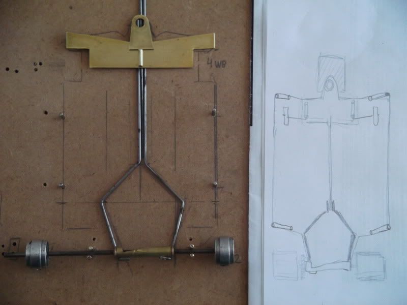
2- Here I added the front body mounting tube and reference rail on the right, plus draw the rest of the main parts and wheels(yes, I do want to have front wheels on my car -at least little ones...)
I would like your opinion/sugestion on the 1. & 2. questions (remember to note the explanation of center flex design earlier):
*I might have to go back to read the rules, this chassis design might be 'not legal',after all, but as I stated before, I'm more interested in the experiment ("Hendrix" would probably agree on this one..)


g.r.
Going ahead with the project, this is what I came up for a plan. (i found a picture on epay where the seller placed a ruller next to a wing car chassis so I was able to estimate the size of the motor box and frame - then I applied to my own design -the rough drawing seen to the right of the mock-up - you'll noticed I changed the size of the front brass piece to go all across the width of the chassis and the overall design changed a little after some more 'contemplation"...
1-The first picture shows a quick mock-up of the main cut brass and rails( I will cut up the 2 rails from the motor box where they meet the center rail and solder all three pieces. The front part of the center rail will fit -but not rattle- into a brass tube (recessed into the main front brass piece) so it can "spin" into the tube to provide flex when the car enters into a corner. the outer(perimeter) rails will be soldered to the motor box and to the top of the front brass piece so they act as a limiter and spring controll for the center flex. ( I hope this line of thinking is in the right path,and produce some good results, because what I've observed is usually the chassis are built with the center rail 'solid' and the outer rails are the ones 'loose' or go into tubing).
2- Here I added the front body mounting tube and reference rail on the right, plus draw the rest of the main parts and wheels(yes, I do want to have front wheels on my car -at least little ones...)
I would like your opinion/sugestion on the 1. & 2. questions (remember to note the explanation of center flex design earlier):
*I might have to go back to read the rules, this chassis design might be 'not legal',after all, but as I stated before, I'm more interested in the experiment ("Hendrix" would probably agree on this one..)
g.r.
Gus Remor
#20
old & gray
-

- Full Member
-
- 1,209 posts Joined: 15-April 11
Checkered Flag in Hand
- Gender:Male
- Location:CT
Posted 01 May 2011 - 09:59 PM
Quick comments on your questions:
Other comments: Don’t sweat the front wheels, they’re justdecorations. Depending on your track you’ll be driving, you may want to floatthe rear body mount to provide some vibration isolation.
- the outer rails should be soldered solid. A hinge joint will just be too much flex.
- Solder the center solid. The hinge mount would provide more “bite” but you can make the same tuning adjustment with tires, body, or air control. Since you are using a brass nose piece you will have more flex than a steel nose.
Other comments: Don’t sweat the front wheels, they’re justdecorations. Depending on your track you’ll be driving, you may want to floatthe rear body mount to provide some vibration isolation.
Bob Schlain
#21
racer g
-
- Full Member
-
- 47 posts Joined: 24-July 08
Rookie Keyboard Racer
- Location:NY
Posted 02 May 2011 - 01:19 PM
thanks for the comments old&gray. I'll have the outer rails soldered solid. I'll experiment with the center rail without soldering for first tests to observe my concept, if it doesn't produce the results I was intending I'll make it solid.
the front brass piece will have piano wire across to give some stability and reduce flex of the front brass piece.
I like the idea of floating the rear mounts for the body, since these type chassis don't use pans or any chassis floating parts,that should help transfer/dissipate the vibration, I'll try that - I didn't know there was this concept for wing cars -so is it enough to float the rear without floating the front mounts? that's how they are usually? do you guys use more body float for flat tracks and tighter for the banked tracks?
-as far as the front wheels, I was just thinking the other day: because of this simple design of the actual chassis, (at least compared to what I'm used with building the retro and GT designs with lots of parts and soldering ) it would probably take me just as long or longer to build the wheels assembly than the actual whole chassis, so I was going to leave them out...I know they have no purpose on this type of chassis,and besides adding to much weight- plus will save me a couple hours of work....(I can't believe i just said I'll have a car without front wheels...is this evolution or 'revolution'...)
racer g
Gus Remor
#22
old & gray
-
- Full Member
-
- 1,209 posts Joined: 15-April 11
Checkered Flag in Hand
- Gender:Male
- Location:CT
Posted 02 May 2011 - 09:22 PM
The car you are playing with is an evolution of the purpose built race car. My version of the floating tube mount was a .050 steel tube in a 1/16 ID square tube (about 1/8 long on each rear corner. The front tubes were fixed 1/16 OD brass which acted as the pivot. I used the same mount for flat tracks and punch bowls.I like the idea of floating the rear mounts for the body, since these type chassis don't use pans or any chassis floating parts,that should help transfer/dissipate the vibration, I'll try that - I didn't know there was this concept for wing cars -so is it enough to float the rear without floating the front mounts? that's how they are usually? do you guys use more body float for flat tracks and tighter for the banked tracks?
You'll find you will be more concerned with body type, mounting height and length, and thickness of air control.-as far as the front wheels, I was just thinking the other day: because of this simple design of the actual chassis, (at least compared to what I'm used with building the retro and GT designs with lots of parts and soldering ) it would probably take me just as long or longer to build the wheels assembly than the actual whole chassis, so I was going to leave them out...I know they have no purpose on this type of chassis,and besides adding to much weight- plus will save me a couple hours of work....(I can't believe i just said I'll have a car without front wheels...is this evolution or 'revolution'...)
Bob Schlain
#23
racer g
-
- Full Member
-
- 47 posts Joined: 24-July 08
Rookie Keyboard Racer
- Location:NY
Posted 17 June 2011 - 01:59 PM
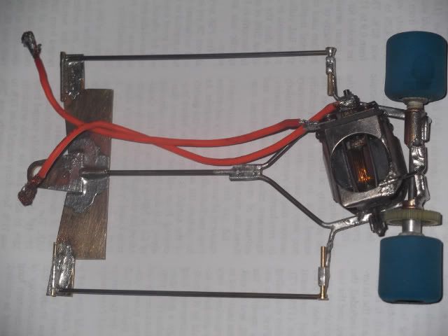
Well, it's been a while, and the car is ready, but I have not had a chance yet to take it for a drive at the local track. I hope to do it soon and post the observations then.
thanks for all the info, suggestions and ideas .
I still would like to add front wheels,(I got a hold of these extremelly light old Camen front wheels) and whenever I get a chance, but want to test run the chassis/car before i go through the trouble...
The rear body mounts into pin tubes and into square tubing, with very slight movement(maybe a 1/64th in) for vibration isolation, and the fronts are fixed pin tubes.(thanks for the idea , old&gray)
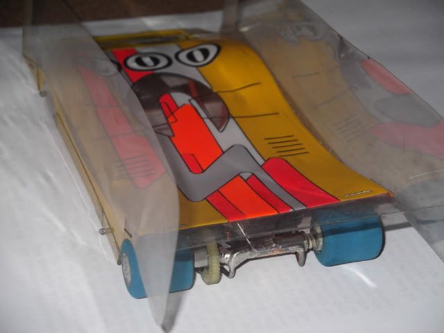
*the body I got ready/used, and have another new/clear Parma body I would paint and assemble if this chassis design/project works well.
thanks for all the info, suggestions and ideas .
I still would like to add front wheels,(I got a hold of these extremelly light old Camen front wheels) and whenever I get a chance, but want to test run the chassis/car before i go through the trouble...
The rear body mounts into pin tubes and into square tubing, with very slight movement(maybe a 1/64th in) for vibration isolation, and the fronts are fixed pin tubes.(thanks for the idea , old&gray
)*the body I got ready/used, and have another new/clear Parma body I would paint and assemble if this chassis design/project works well.
Gus Remor
#24
Bill from NH
-
- Full Member
-
- 14,778 posts Joined: 02-August 07
Age scrubs away speed!
- Gender:Male
- Location:New Boston, NH
Posted 17 June 2011 - 04:41 PM
Gus, your chassis looks pretty nice! Your body is an Outisight Tiga. Clear ones are still available as part # OS-028. Let us know how this car works, once you've had it running on the track.
Bill Fernald
I intend to live forever! So far, so good.
I intend to live forever! So far, so good.
#25
Uke
-

- Full Member
-
- 29 posts Joined: 14-June 11
Rookie Keyboard Racer
- Gender:Male
- Location:Dallas, TX
Posted 15 August 2011 - 02:46 PM
Was curious if you ever tried the car???
Ryan
Ryan
Ryan Lisko
Home track: Wylie Motor Speedway
Home track: Wylie Motor Speedway


