


One of the most important factors in a good-handling slot car is the guide flag set-up. The guide flag must turn freely and smoothly, without any binding whatsoever, and there should be as little play and "wobble" as possible between the guide and the guide tongue.
In the "old days", the most commonly-available guide flag was produced by a single manufacturer, whose mold was arranged six-up, i.e. a single shot of molten plastic ended up as six guides on a sprue, or tree. There was a faint position number on each molded guide and due to various factors, like the rate of cooling across the mold and the precision of the tooling, certain numbers were favored over others as having the "truest" posts square to the guide flag body.
Today, most guide flags are accurate enough in this parameter. But some subtle mods can make a good guide even better.
My experience indicates that pure nylon guide flags are more durable than the graphite-filled plastic guide flags. The latter seem more brittle, though they are probably stronger than the nylon units. Bottom line is I broke more of the black ones over time, so I avoid them now.
First, a common failure mode for guide flags is breakage of what I term the braid clip "box" or "braid box". This is the flat rectangular cavity into which the braid clip is pushed to retain it in the guide flag. Often when crashing into the rear of another car, the sharp edge of the rear part of the chassis being hit slices into the braid box, splitting or peeling the top or side back so that the braid falls out more easily. Not much can be done about this problem without a redesign of the guide flag tooling. If, for example, the square rib on the top of the guide was extended forward to align with the upper corner of the blade, some of the hits that damage the braid boxes might be deflected.
A second common failure mode for guide flags is for the post to snap off the guide flag body. No picture here, but I think anyone who has raced 1/24 slot cars has seen this happen, at least once.
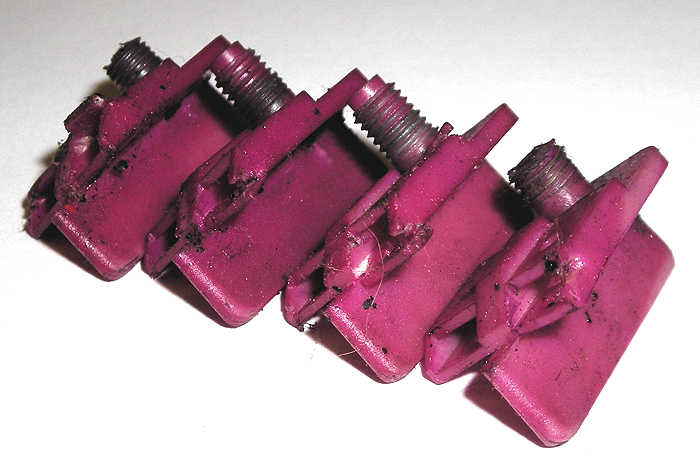
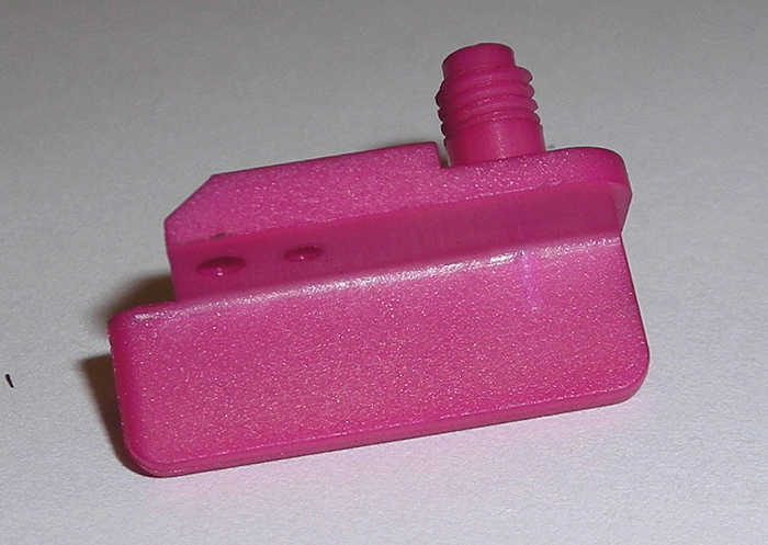
To address the post breakage problem, one can take a Parma Blade guide flag, which comes with a molded hole atop the post, and extend that hole down into the actual blade of the guide flag. Then a piano wire pin can be inserted to strengthen the post to body attachment. Here is a picture of a new Parma Blade that has had the hole extended.

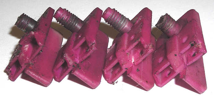
Use a drill press to hold the drill bit vertical and square and extend the molded hole in the post down into the guide flag blade itself roughly 1/3 to 1/2 of the blade height. Support the guide flag with a tech block on the drill press table, to help hold the guide post upright and square. The pictures of the sides of the blade should show that hole in the blade stays centered reasonably well.
The piano wire "reinforcement" can be dipped into super glue before being hammered into the hole, but that has proved to be unnecessary. Just be certain to get the wire to the end of the drilled hole.
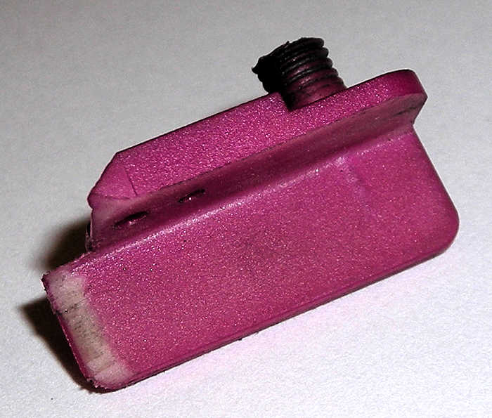
Squareness and concentricity are important factors in realizing wobble-free guide flag operation. One approach is to use a Magnehone diamond tool to true the top surface of the guide.


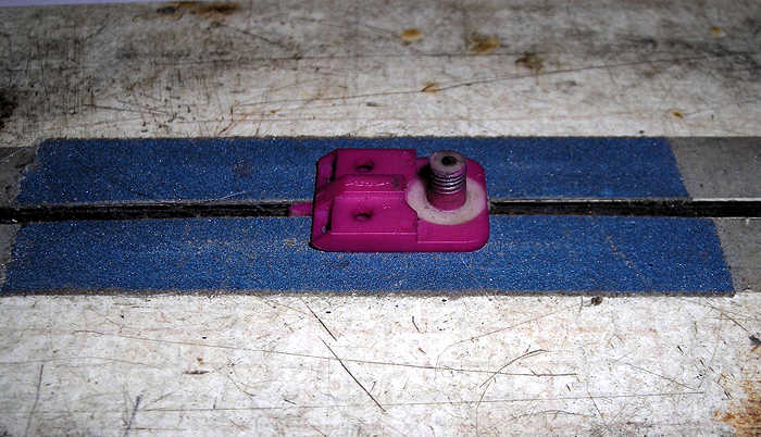
There are several other "tweaks" one can make to guide flags. Any time you inject hot plastic into a mold, dimensional changes occur as the hot plastic cools. These changes can cause, for example, the flat surfaces that support the braid actually not to be very flat at all. So it is usually worth sanding those surfaces to make them flat. A couple of strips of emery cloth transfer-taped adjacent to the slot on a spare tech block will do the trick.

A little time with a small file also can improve a guide. Note that the "nose" on this guide has been "knife-edged". The blade of a Parma Blade guide flag is actually wider at the bottom than at the top and the filing is carefully blended into a triangular shape. Compare this to the rounded leading edge of the new guide shown earlier.

Another potentially helpful modification is to to round or "soften" the very front corners of the guide body to prevent them from digging in or "snagging" track imperfections. This mod also works to make the flag braid contact the track braid more completely, as suggested by reading braid wear patterns over time. This mod should be discernible in several of the images shown.
Finally, just as the guide top surface was trued, one can also true the bottom surface of the guide nut itself. (A central tenet of "blueprinting" is never to assume that surfaces that are supposed to be 90 degrees square to each other actually are.)
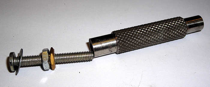
One method is to use a longish machine screw of the proper pitch and a jam nut. Run the jam nut in just short of bottoming the screw in the Magnehone tool, to provide the most "piloting" effect, and "jam" the plain nut and the guide nut together to lock them in place at that point. Then use the Magnehone tool to grind or surface the bottom of the guide nut. It is surprising how often the bottom of a guide nut is not square with the centerline of the threads.
Here's a pic of several Koford nuts that have been trued, along with the preferred wide and true Koford bronze guide flag washers.

As mentioned in the T-Flex tome, you can also use the Magnehone guide tool to surface or face the top and bottom of the guide tongue as well. Hold a guide flag with an unshortened post firmly on one side of the tongue, with the post projecting through the hole. Then "pilot" the Magnehone tool on the post and grind away, and reverse the set-up to do the other side.
Facing all of the surfaces involved in the guide system makes it far easier to achieve the smooth, easy-turning, wobble-free set-up that is the goal.
I actually know few a other guide flag tricks used by other racers (plus some of my own that are less than legal...
 ) but if I revealed any of those, I'd be at serious risk of assassination! LOL!


