Paul,
No, not for the Sandy Gross Anglewinder F1, because I've never had the chassis in my hands to measure it.
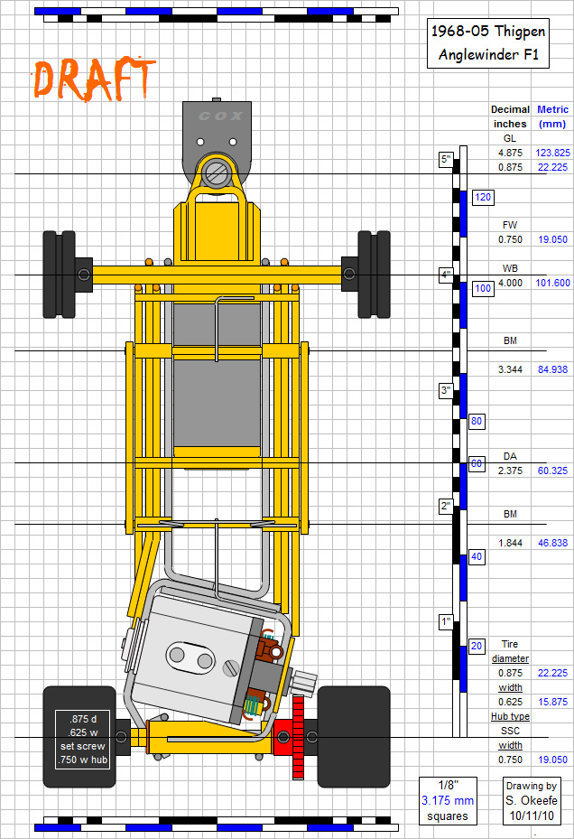
Rick Thigpen was kind enough to put his anglewinder F1 chassis in my hands, so here's a drawing of it:

Wanting to design my own version, I worked out this drawing:

1968 Car Model rules did not anticpate the anglewinder drive, so there are no rules specifically addressing how the motor or gears must fit under the body in an anglewinder F1. Body manufacturers did not anticpate anglewinder drive either, so F1 bodies were generally no wider than about 1-3/8". They could be "stretched" to about 1-1/2" wide, but that's pretty much the limit.
Normally, an anglewinder motorbox is something like 1-5/8" wide, no problem in a sports car or coupe, but BIG problem in a F1. Add to that the new (for then) plumber style F1 body mount, consisting of one additional 1/16" piano wire rail on each side, and now the chassis could be as much as 1-3/4" wide (depending on how you build it). Clearly this isn't going to work: The whole chassis should be no wider than 1-1/2" including everything.
The designs of all the anglewinder drive cars in this May, 1968 race reflect this, and since you've read the race report, you're fully aware this is definitely a "pro" build. Note the can must be shortened to .800" long to make everything fit. In stock form, the Mabuchi FT-16D can is approximately .965" long, so it must be shortened by about .165" (just over 5/32"). This means you're going to have problems with both stock magnet and stock armature length.
In this design, the rail configuration around the motorbox is very important, but in the above drawing it is concealed by other parts (a pet peeve of mine regarding magazine chassis drawings of the period), so here's a detail drawing with the motor, bracket brace and waist strap removed. Note the chassis, including everything, is 1-1/2" wide:

Have fun building this one... 


