Jump to content


Photo

Building an FT-16D Type 1 motor


  • Please log in to reply
3 replies to this topic

#1 Steve Okeefe

Steve Okeefe

    The Independent Scratchbuilder

  • Administrator
  • PipPipPipPipPipPip
  • 1,139 posts
  • Joined: 16-February 06
  • Gender:Male
  • Location:State of Independence

Posted 12 March 2013 - 09:05 AM

A Recreation 1967 Mabuchi

FT-16D Type 1

For the Morrissey Group III Pro Series "What-if " Sports Car

By Rick Thigpen


Motor time for the Morrissey "What If" sports car.


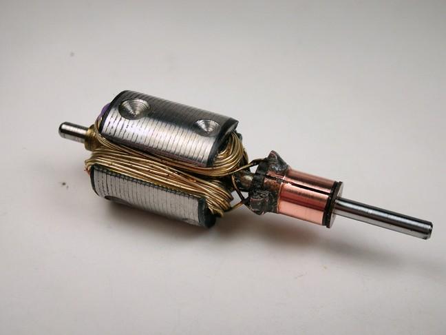
I'm going to use an unknown vintage silver wire armature (French-Tradeship?) that I've used before. It ran pretty strong and I hope to make a motor setup that will help it last a while. What I'm doing is what I've read and what people have advised me works well. I'm sure there are more things I could do or things others would do differently. That's just fine.  Everyone should do what they are comfortable with.....I do and I am.


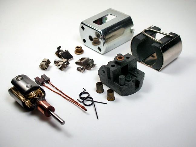
Here are the motor parts I'm going with (for now).  A Cox TT100 can with the blind bearing to be replaced with an end bell bearing and ARCO 33 magnets and shim.  I'm going to use a Tradeship end bell that looks like a Cox but is molded of a higher temperature plastic (I hope).  I'm also going to use shunted 16D brushes and brass spring post protectors in hopes of avoiding a melt down.  The armature is a vintage silver wire "mystery arm":


31-Morrissey motor.jpg


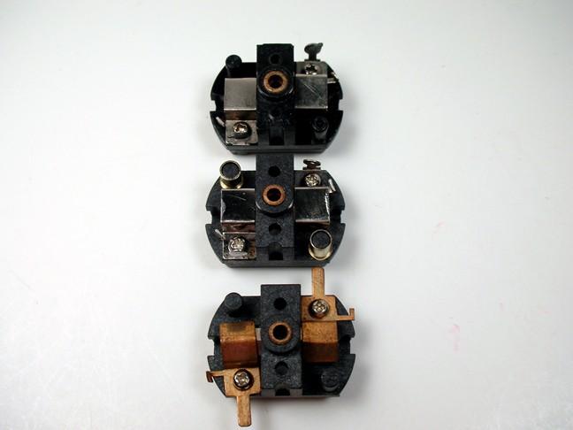
My motor is supposed to look like a period Cox TT100 can with a TT150 end bell.  However, I'll be using a Tradeship end bell that is made out of a higher melting point plastic.  It's almost a dead ringer for the Cox-Mabuchi.  On top is the Cox TT150-Mabuchi end bell.  On the bottom is the stock Tradeship, and in the middle is my Tradeship with Mabuchi brush hoods and brass spring post protectors:


32-Morrissey motor.jpg


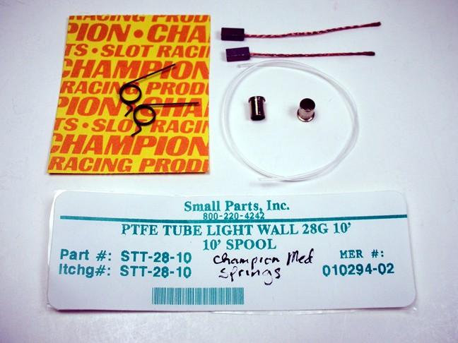
Here are some of the parts I hope will make this motor be fast and last.  Vintage shunted brushes and brass spring post protectors and modern Champion medium brush springs and my "Invisible" brush spring insulation.  My goal is to isolate the plastic spring posts from heat.


33-Morrissey motor.jpg


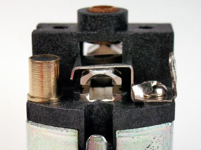
The hex brush holders are still just sitting on the plastic end bell and will get hot.  We've all seen them melt down into the end bell.  Here's something I've seen on some old motors.  At first I thought it was just to help with electrical conductivity.  It seems to me that this trick would also stabilize the brush holder if the plastic beneath it starts to get hot and soft.  Note how the brush holder is soldered to the brush hood with high temperature solder.  Maybe this is all a bunch of baloney but it looks cool:


34-Morrissey motor.jpg


This is what works for me when soldering brush holders to brush hoods:


1. Glass of water at the ready


2. 1,100 degree iron cranked full blast


3. Flow acid flux onto aligned brush holder and brush hood


4. Pick up dab of solder with tip of iron and touch it to joint for about 1 second


5. Throw that puppy into the glass of water muy quicko


6. Wipe tears from eyes from melting nylon if you were too slow


7. Run to sink and scrub end bell with Dawn and tooth brush (end bells do not like acid flux but the solder sure does)


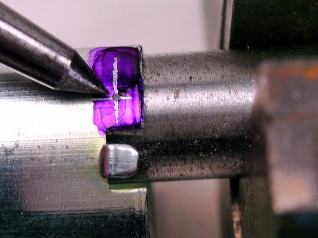
To attach the end bell to the can I used armature dye (which is really machinist layout dye) and scribed some lines on both sides of the can.  You can use your cheapo dial calipers for this and your screws will end up in the same location on both sides of the can.  I used a prick punch and a 3/8" steel rod held in a vise to back up the can during punching:


35-Morrissey motor.jpg


I'm not using self tapping screws because I don't like them. I'm going to use a common 0-80 machine screw that was available in the 1960's and before. This makes me happy. Please screw yours the way that makes you happy too:


36-Morrissey motor.jpg


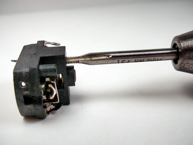
These end bells are a little brittle and can crack so I thought I'd forgo the self tapping mounting screws in favor of a 2-56 machine screw.  When tapping a through hole like this end bell a "gun" style tap is handy.  It pushes the chips out the back end of the hole.  You can see the chip coming out the back of the end bell. You can also just crank away on a gun tap.  You don't have to do the 2 turns in and a half turn out to break the chip as you would on a conventional tap.  Just make sure you start the tap straight so your screw will be nice and square with the end bell:


37-Morrissey motor.jpg


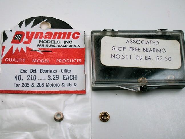
I cut off the blind bearing with dykes....hmmmm....maybe I should say side cutting pliers?  Anyway, I'm replacing it with an end bell bearing.  Back in the day we used to use Mabuchi bearings but today I need those to rebuild end bells.  I have a pile of these Associated bearings so that's what I'm using. Here's the Mabuchi - Mura - Dynamic end bell bearing and the Associated bearing:


38-Morrissey motor.jpg


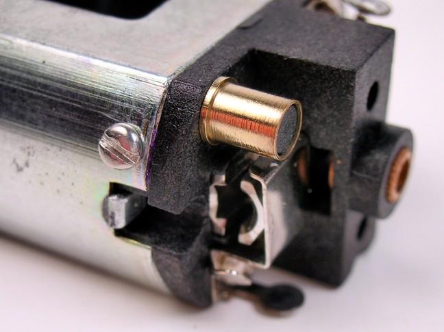
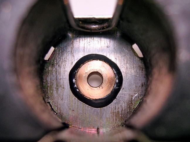
I've always soldered them in the can but this time I thought I'd try JB Weld metal filled epoxy.  I put a dab all around the bearing flange and pushed it into the can.  It left a little fillet of epoxy around the bearing like so:


39-Morrissey motor.jpg


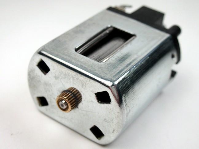
No goobers on the outside of the can so it looks neat:


40-Morrissey motor.jpg


Next I'll stuff this mystery armature in and rig up the brushes, shunts and insulation:


41-Morrissey motor.jpg


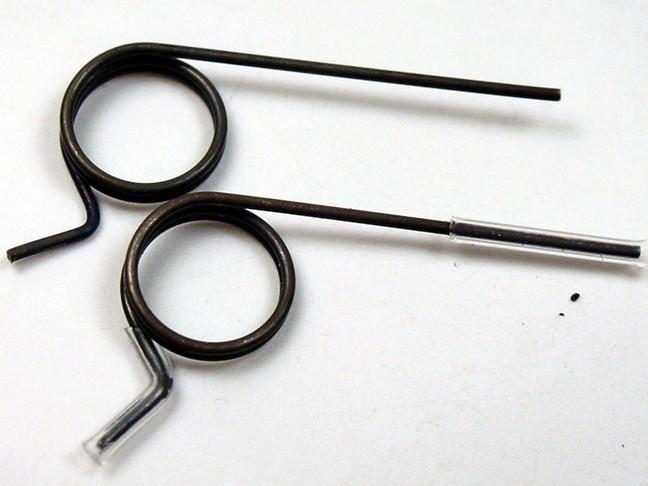
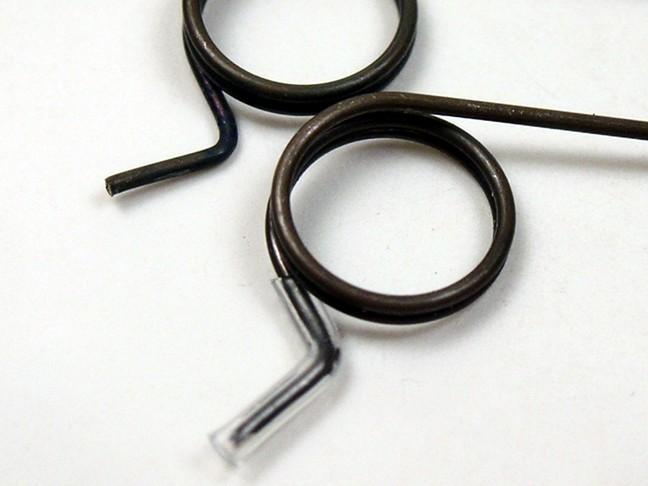
Here on top is a stock modern Champion medium brush spring.  On the bottom is the spring with my invisible (almost) Teflon brush spring insulation installed and the spring slightly bent to better fit the brush:


42-Morrissey motor.JPG


Here's a close up of the insulation.  I pushed it farther than most do.  I really want to isolate the spring and plastic spring post from the brush and shunt wire:


43-Morrissey motor.JPG


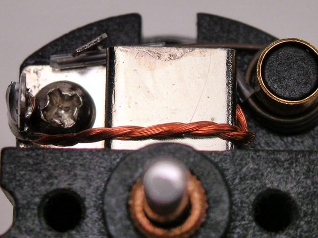
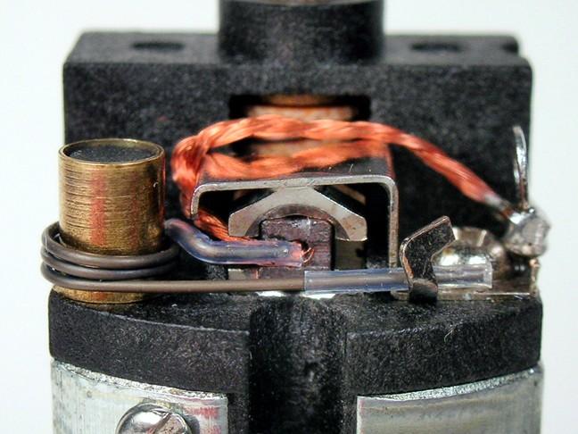
You can see here that the relationship between the spring, shunt wire and insulation:


44-Morrissey motor.JPG


45-Morrissey motor.JPG


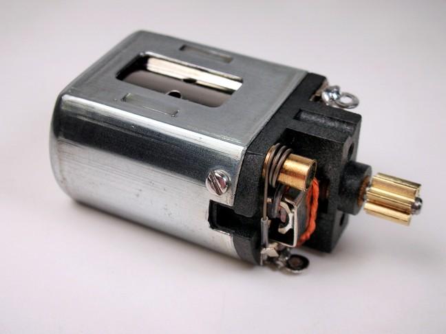
And the finished motor:


46-Morrissey motor.JPG


I don't think the Pros were insulating their brush springs in 1967 so that's why I choose the clear Teflon tubing.  You really have to look hard to see it on the car.


I should also mention that I messed around with armature to magnet alignment.  Sometimes I hone the magnets.  Sometimes I use an alignment tool and if things are out I'll open up the bearing hole in the can until things line up and then solder the bearing in.


This motor was pretty well in alignment (by some miracle) so I just epoxied the bearing in the can.


Anyway, it runs on the power supply.


  • MarcusPHagen likes this

Steve Okeefe


I build what I likes, and I likes what I build


#2 Steve Okeefe

Steve Okeefe

    The Independent Scratchbuilder

  • Administrator
  • PipPipPipPipPipPip
  • 1,139 posts
  • Joined: 16-February 06
  • Gender:Male
  • Location:State of Independence

Posted 26 November 2013 - 03:34 PM

Over time I've come to the conclusion that soldering the brush holders to the brush hoods is VERY important (you might even say "critical") to improving any endbell's chances of surviving a "hot" armature.


This is especially important when building pre-1967 Mabuchi FT-16D motors, which used the original white endbell without spring post protectors or brush shunts.  There are at least two good reasons why:


1. It provides a significantly lower resistance pathway for electrical current to or from the brush.


Without the solder fillet the only paths the current has to get to the brush holder is through the tiny (think higher resistance) contact point where the hood presses down on the holder, and through the brush spring.  Conducting current through the brush spring turns it into a heater coil that promptly melts off the spring post.


2.  It supports the brush holders and keeps them aligned even if the endbell begins to melt.


The trick of course is that the hoods (not the sockets in the endbell) are now keeping the holders in alignment.  The hoods cannot be pressing-down on the holders when they are installed. 


Soldering brush holders to brush hoods while mounted in the endbell might seem a little bit like dropping an ice cube into a hot frying pan and expecting to not melt (it did to me at first), but it can be done.  My process is similar to Rick's, except no acid flux or glass of water:


1. Check to see that the brush holders are aligned when installed in the endbell you plan to use.  Caution: Don't skip this step - brush holders are not necessarily all alike - I've seen a few that are way out of whack!  I use a piece of 3/32" square brass tube for 16D size brushes, or a commercial alignment bar for 36D size brushes.


2. Tweak the brush hoods until they are just barely touching the tops of the brush holders; you don't want them pressing down on the holders, either when soldering or later when running the motor at high temperatures!


3. Disassemble the endbell and tin the surfaces of the hoods and holders where they will contact each other.  Leave a tiny blob of extra solder on the brush holders.  You can use any type of solder that strikes your fancy.  Clean up the parts to remove all flux residue.


4. Clamp the brush holder alignment bar in a small vise attached to your workbench so that about 2 inches sticks out (horizontally or vertically, it doesn't matter; whatever works best for you).  Put a small dab of non-acid paste flux on the inner surface of the brush hoods and reassemble the endbell.  Slide the endbell onto the alignment bar through the brush holders.


5. Touch the flat side of the tip of your 1100 degree soldering iron to the brush hood.  The flux should liquefy in about 1 second, followed immediately by the solder.  Watch this carefully to get a "feel" for how long it takes; probably less than 2 seconds total.  You can add more solder during this process if you like, but you shouldn't have to.  Remove the iron and let the joint cool.


Unless you went way overboard with the heat, the alignment bar should act as a heat sink and protect the endbell.  Reverse the endbell on the alignment bar and repeat the process.  Then disassemble everything again and clean up any remaining flux residue.


Piece-o-cake! :good: 


  • MarcusPHagen likes this

Steve Okeefe


I build what I likes, and I likes what I build


#3 TSR

TSR

    The Dokktor is IN

  • Full Member
  • PipPipPipPipPipPipPipPip
  • 42,299 posts
  • Joined: 02-February 06
  • Gender:Male
  • Location:Marxifornia

Posted 26 November 2013 - 03:51 PM

Great job!

I recommend making a small hole in the brush holder cover piece, so that the solder can flow nicely through the hole and onto the top of the brush holder. We have some old Steube motors done that way, it makes for a very clean job.


  • MarcusPHagen likes this

Philippe de Lespinay


#4 Hworth08

Hworth08

    Posting Leader

  • Member at Peace
  • PipPipPipPipPipPipPip
  • 3,563 posts
  • Joined: 16-February 06
  • Gender:Male
  • Location:Springfield, TN

Posted 26 November 2013 - 06:15 PM

It was a tedious operation but we soldered twin lead wires to the brush holder to carry away the heat.
We ground a V into the brush holder hold down piece to gain some access. We preformed the task in an end bell that had one side already melted, it wasn't easy to do!

Some Steube type holes to hold things would have helped.
Don Hollingsworth
11/6/54-2/13/18
Requiescat in Pace


Electric Dreams Online Shop