Sandy Gross Puzzle Pan
Page 5
Installing body mount up-stops, attaching the motor plate and installing the front axle mount
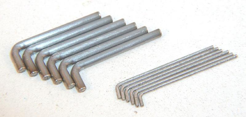
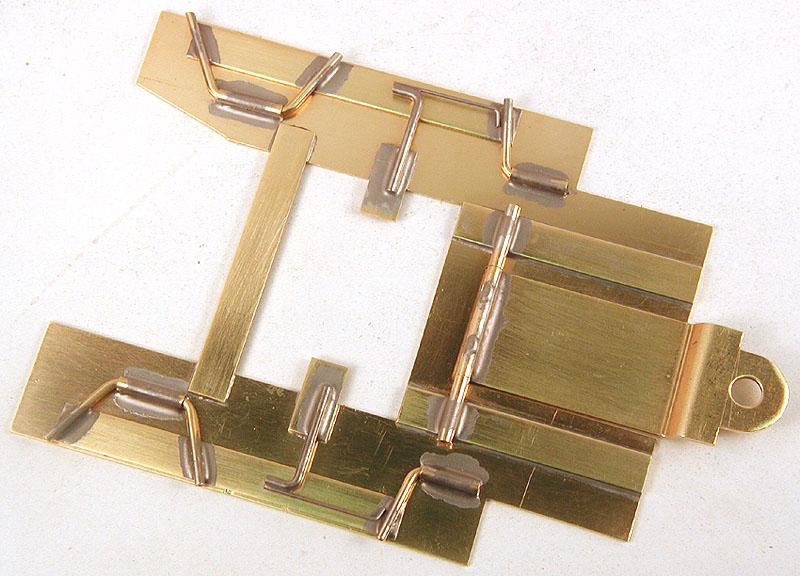
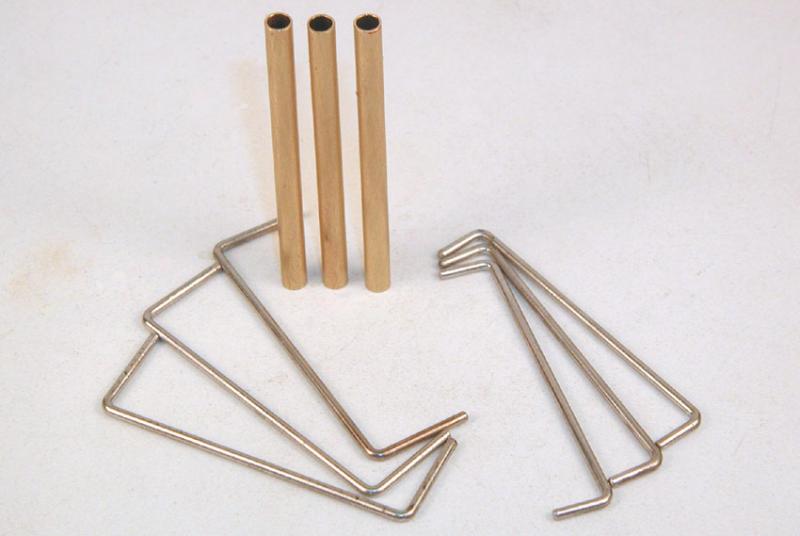
Bend some bits of piano wire to make the up-stops and springs. Don't forget to tin them; it makes installing much easier:
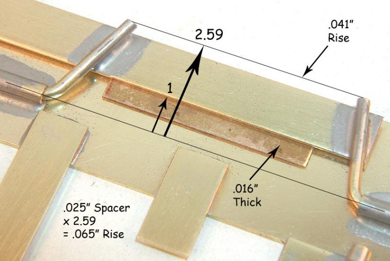
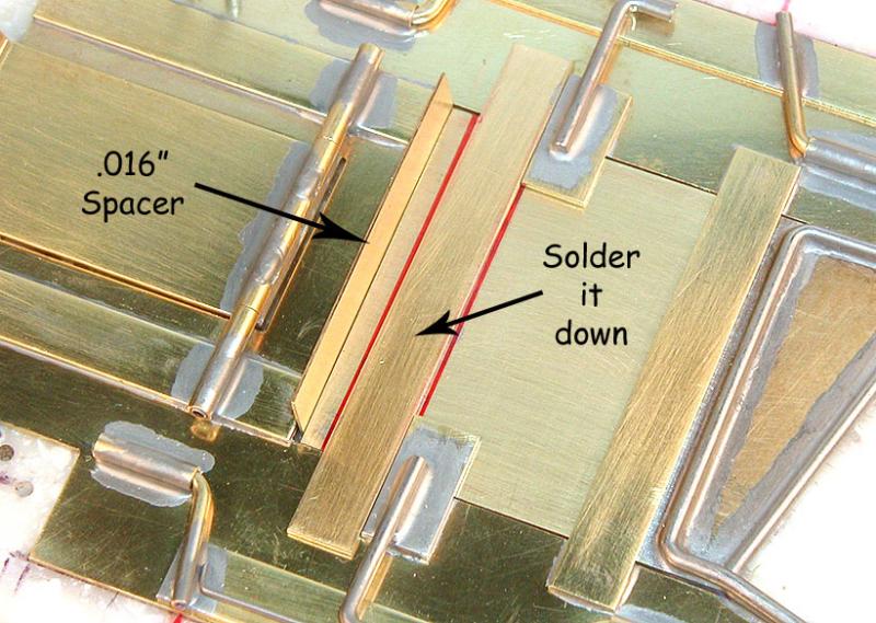
Set the desired body mount rise. Here I've used an .016" brass shim under the inside edge of the body mount to get an .041" rise at the tips of the pin tubes. If you remember your simple machines (levers) from basic high school physics, you should have no problem understanding this. If you don't remember, just take my word for it, it works. If you want more rise, use an .025" shim; it will give you .065" at the tips of the pin tubes:
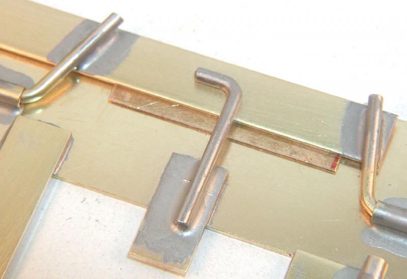
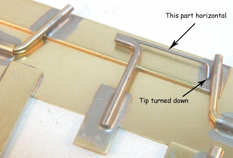
Solder the up-stop down to the top of the stepped motor plate up-stop. It will be tilted up slightly, but is not really a problem. Try to make sure the hook of the up-stop is flat against the body mount. You can avoid un-soldering the stepped up-stop from the main pan by using the tip of an X-acto knife to firmly hold the stepped up-stop down while you solder the body mount up-stop to it. You will need three hands to do this :-)
Instead of trying to grow a third hand (or having Donna help you), you can hold tiny bits like this in place while you solder using a few odds and ends from around the workbench. I use a collection of scrap metal blocks and small metal slabs that I've gathered over the years from various machine and sheet metal fabrication shops, along with some old worn out 4" and 6" flat files.
The blocks range from 1/4" to 3/8" thick, 3/4" to 2" wide and 2" to 4" long. I have one large
block that's about 9" long for the really big jobs... What makes them so very useful (besides their weight) is that they have flat sides, sharp corners and square & parallel edges.
In the case of these up-stops, I stack up some blocks so that a small flat file can be set down more or less horizontally with the tip of the file on the blocks, and the tang (the part that goes into the handle) laying on the hook of the up-stop, pressing it down flat on the body mount. Now I will place an additional small block (or two) on top of the flat file to make it press down a little harder.
At this point I still have my two hands available; one to hold the x-acto knife, using it to press down on the stepped motor plate up-stop (holding it in place), and the other to hold the soldering iron...
Use this same sort of process to hold the tiny spring in place while you solder it to the up-stop:
Crude as it might seems it does work rather well...
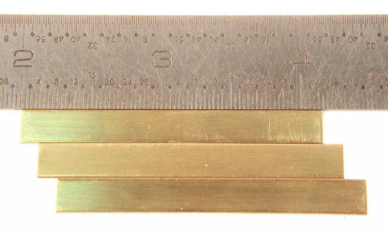
Now mechanically interlock the motor plate into the main pan. Start by cutting some .032" by 1/4" brass strip about 2-5/32" long:
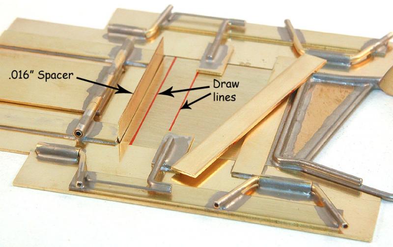
Set the main pan and motor plate in the jig. Insert the .016" spacer shim between the main pan and motor plate as shown, lay the brass strip up against the stepped motor plate up-stops as shown, and draw two outlines:
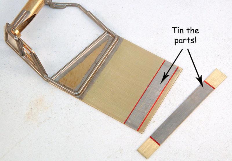
Remove the motor plate from the jig, and tin it and the brass strip:
Note: Once you do this step, you cannot remove the motor plate from the main pan without un-soldering something; be sure you re-check to see all the parts are aligned properly, and have all your ducks standing in a nice straight line before proceeding!
Lay it all back into the jig, including the .016" spacer shim, making sure the motor plate and the brass strip are centered, and the brass strip is pushed up against the stepped motor plate up-stops.
Another building trick: space the whole assembly up off the jig block using two or more pieces of 1/16" brass strip to keep the block from absorbing the heat. Doing this will insure the soldering goes quicker so that the other solder joints close by don't have time to melt and shift around.
Now, tack the brass trip down. Remove the spacer shim and shift the motor plate forward against the main pan, and finish soldering down the strip.
Moving the motor plate forward against the main pan helps keep molten solder from getting under the stepped motor plate up-stops, which would be very bad news. You can also put a small drop of oil under the stepped up-stops to discourage solder from wicking in.
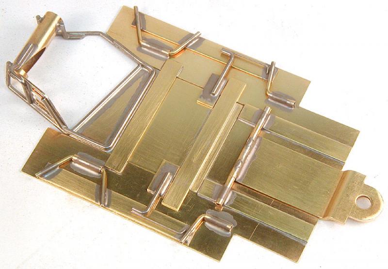
Now, clean it all up again, and it should look like this:
You may notice the back end of the motor plate falls away when you pick up the chassis; it needs a down-stop for the motor plate. You may have also noticed the .032" thick brass motor plate could use a bit of bracing to help keep it from bending in crashes. The next two braces accomplish both at once.
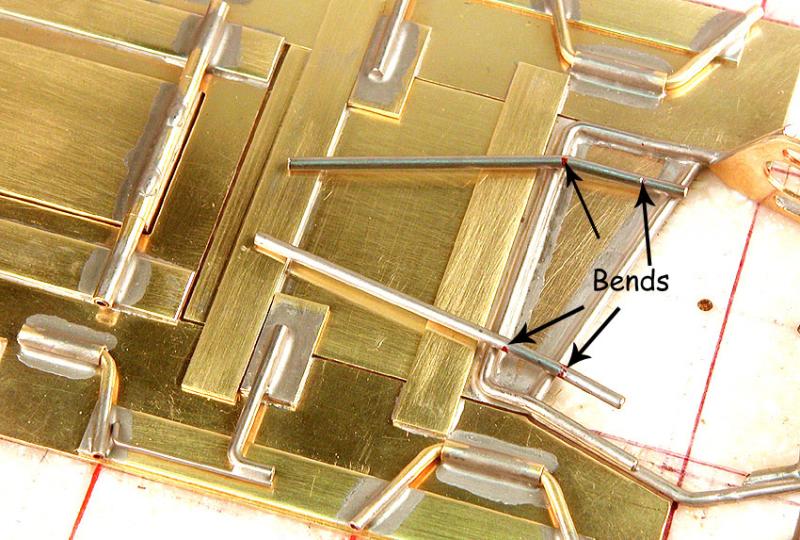
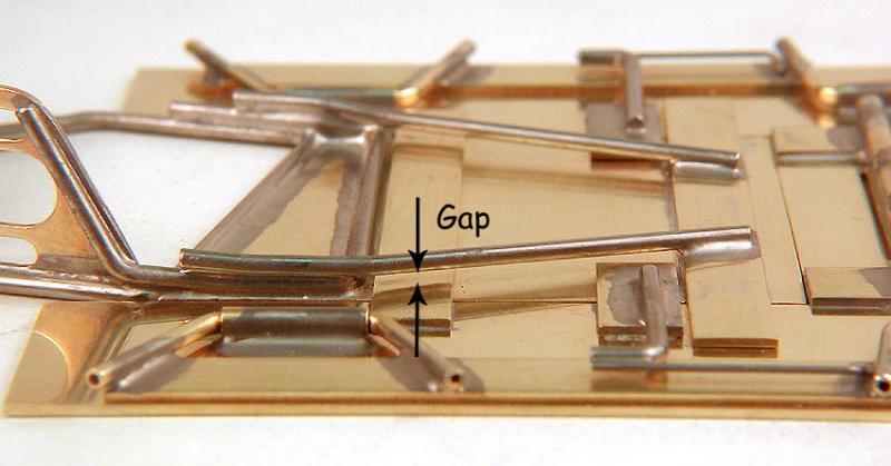
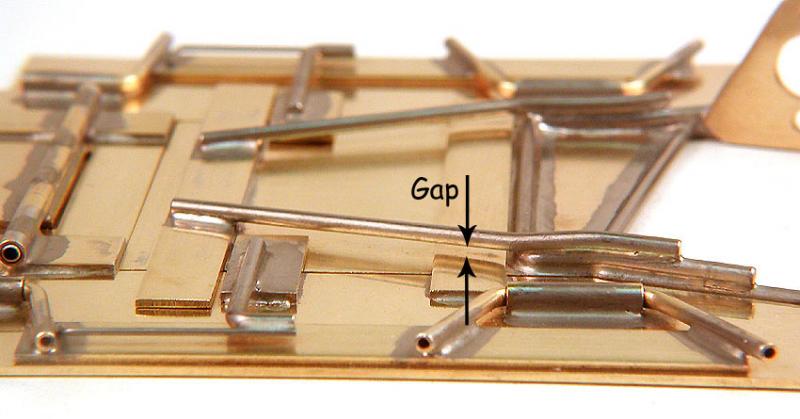
Bend some .063" piano wire as shown here so that it fits over the top of the existing motor box brace:
Tin the two pieces and install them so that the front end is soldered to the brass strip that retains the motor plate, and the back end is soldered to the tops of the motor box brace:
The trick is to leave a gap (about 1/32") between the brace and the rear motor plate up-stop:
Right side (above) and left side (below).
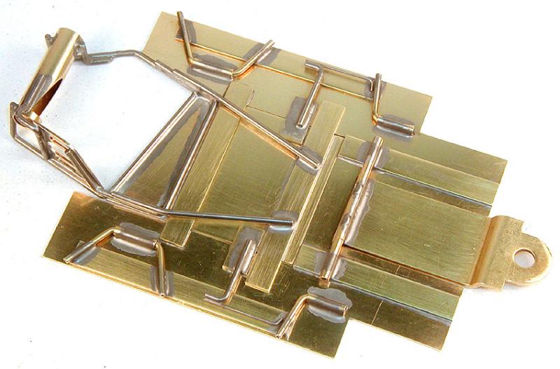
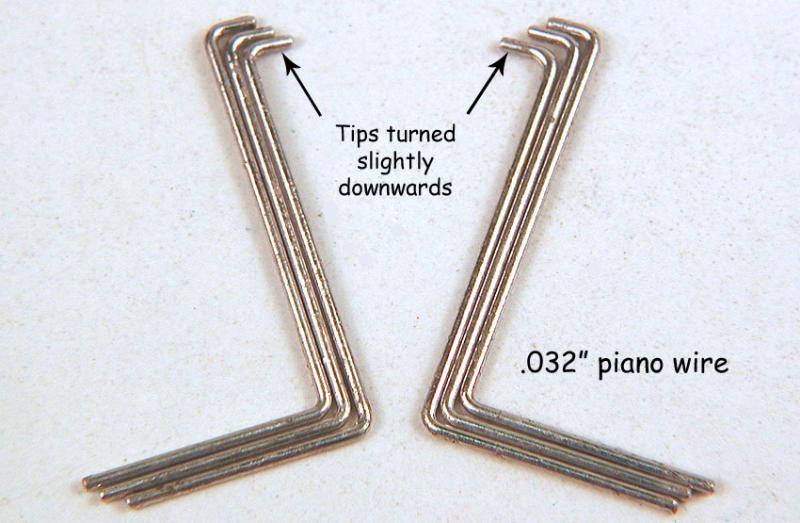
Now the back end of the motor plate has some vertical movement restricted to about 1/16" at the rear axle. Now bend and tin some .032" piano wire to spring the front end of the motor plate down:
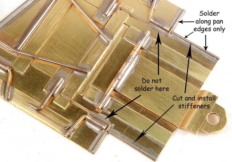
And install as shown, along with some straight pieces of .032" piano wire to act as stiffeners:
Almost finished!
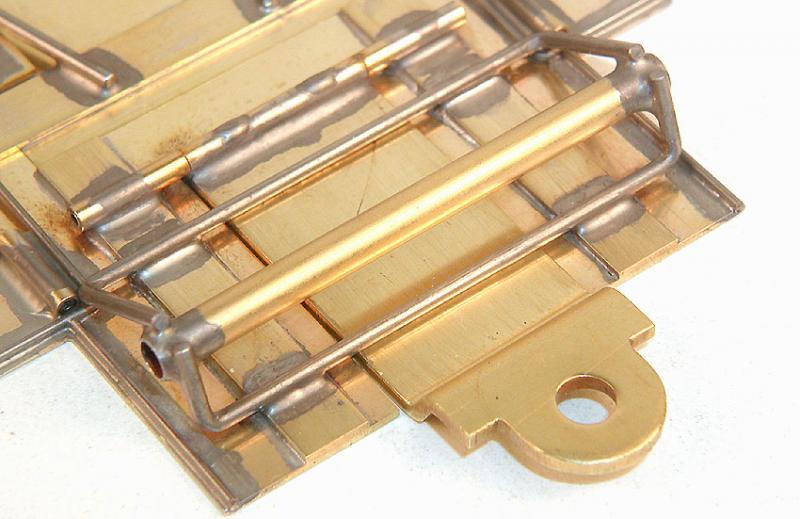
Bend some .063" piano wire to form the dropped axle tube mount, and some 5/32" brass axle tubing:
Set the chassis in the jig, and the front axle with the axle tube in some jig wheels, and install the dropped mounts, front and rear:
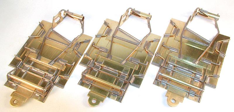
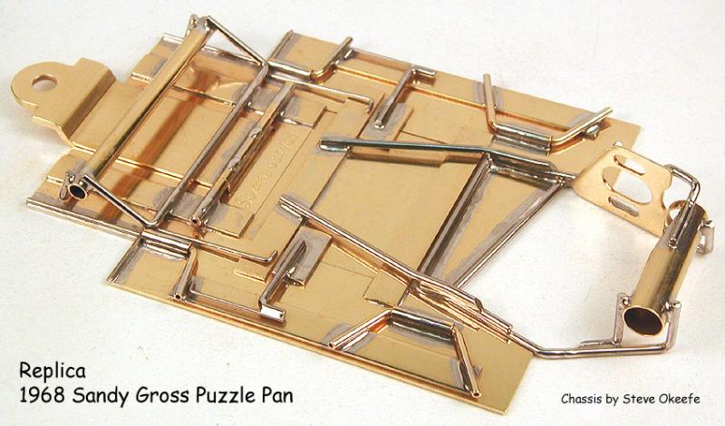
Clean it all up once again, and the chassis construction is finished:
For the record, the finished chassis weight is 86 grams (3.03 oz.), 20% more than a whole Box 12 wing car…
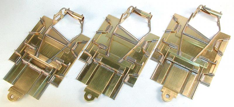
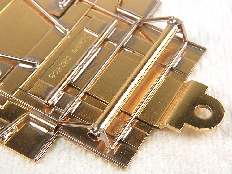
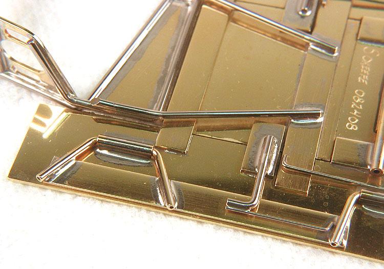
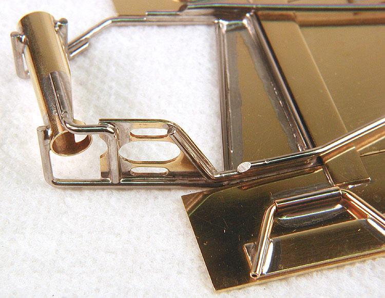
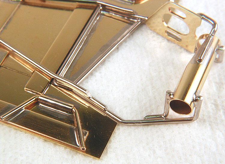
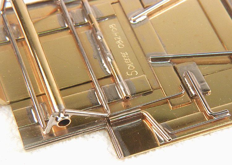
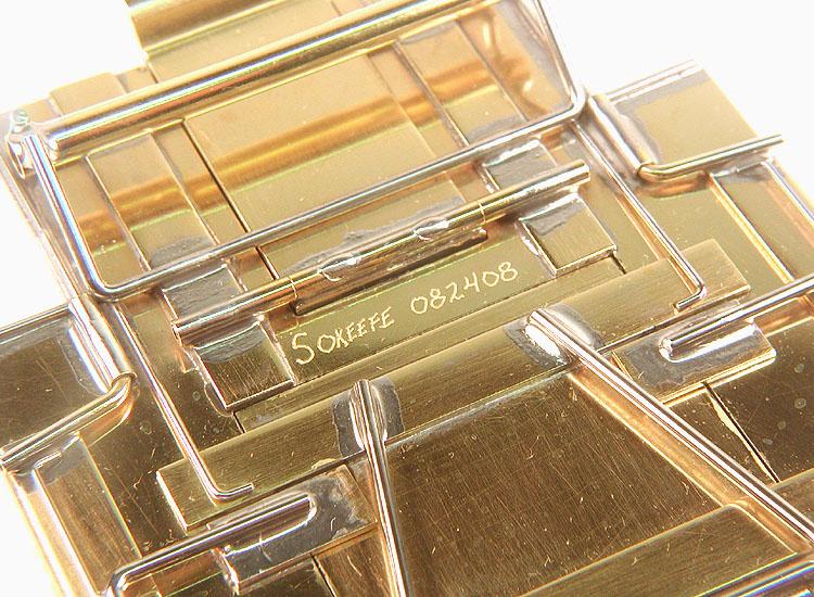
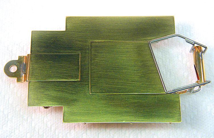
Here are some close-up photos of the chassis I gave Sandy to thank him for all his help with this project, which would not otherwise have been possible:


