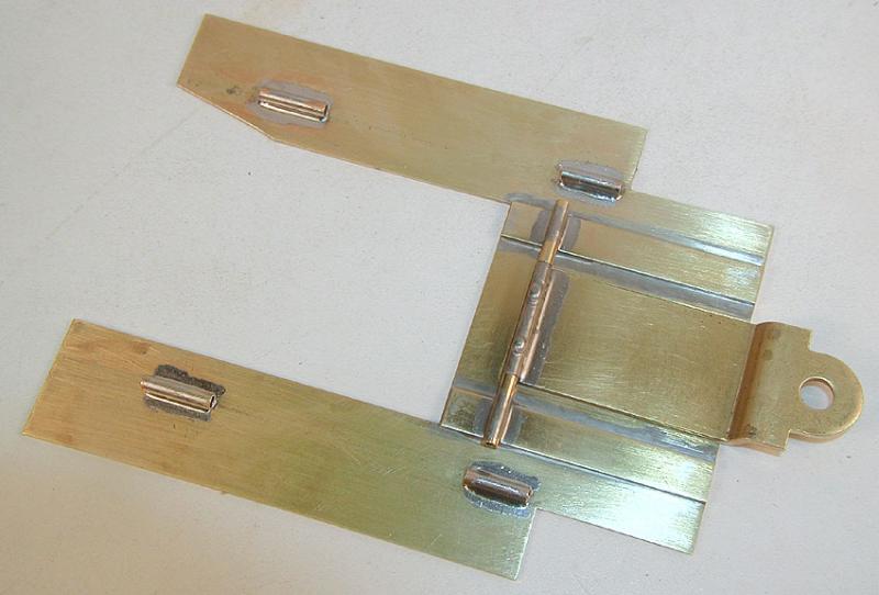
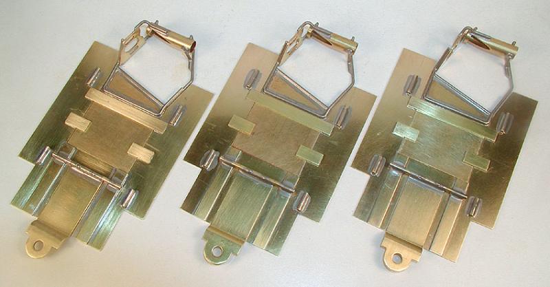
Sandy Gross Puzzle Pan
Page 4
Finish the drop arm, add motor plate stops and hinged body mounts
Having had a day or two to think about the next step I realize there are a few "gotchas" in the design. For example: The front body mount hinge tube blocks the drop arm hinge pin, so if you install the body mount hinge tubes before you finish the drop arm, you won't be able to install the drop arm hinge pin! So, first order of business is to finish the drop arm assembly.
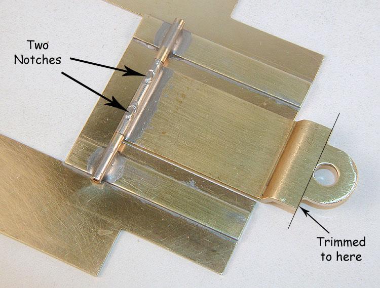
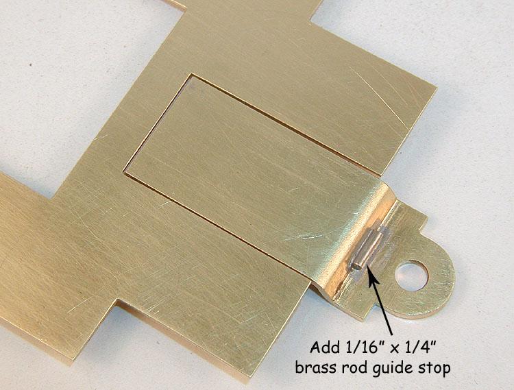
Cut two notches in the drop arm hinge tube, and trim the nose back around to the rear edge of the guide post hole as shown. Cut a 1/4" long piece of 1/16" brass rod to act as a guide stop and solder it to the bottom of the drop arm, also as shown. Install the drop arm hinge pin and solder it in through the two notches you cut in the hinge tube.
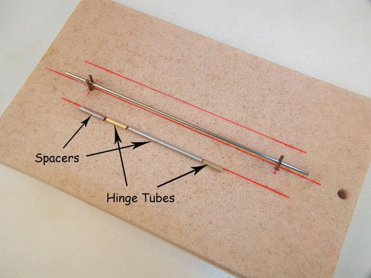
Now we can begin installing the body mount hinges. I'mleery about "eyeballing" critical alignments, so I'm going to makemyself a simple jig to get it right every time. My jig must locate twohinge tubes relative to each other and relative to the edges of the main pan.
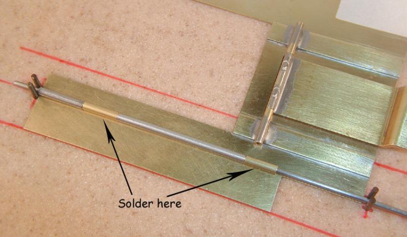
My solution is to string, like beads, the brass hinge tubesand two aluminum tube spacers on a piece of piano wire, and hold the assemblyin the correct location on the pan while I solder it down:
The jig (which took another whole 20 minutes to make) allows me to do both left and right sides with equal precision. Here's what it looks like when it's done:
Before we continue with the body mounts, I want to stop and install the motor plate up-stops, because it's a lot easier to do before finishing the hinged body mounts. In fact, it's probably more logical to do this before even starting the hinged body mounts, and in the future that's the order I would do it in; drop arm, motor plate up-stops, hinged body mounts. Hey, I'm learning as I go.
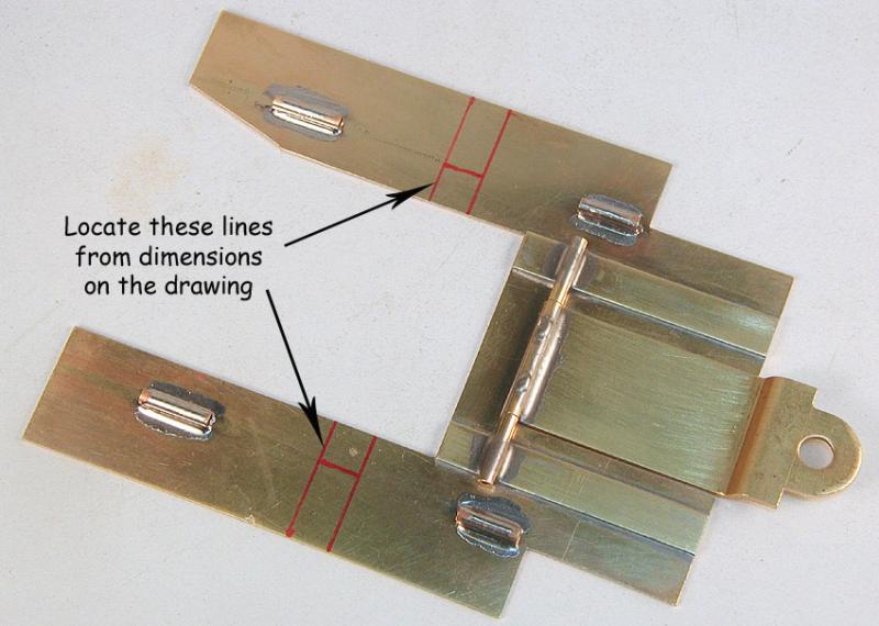
In the meantime, mark out the position of the "stepped" up-stop using dimensions from the drawing:
What is a "stepped" up-stop, and why is it necessary?
If you solder a stop to the motor plate extending out over the main pan, it will prevent the motor plate from dropping down. In the same fashion, if you solder a stop to the main pan extending out over the motor plate, it will prevent the motor plate from rising up. Good so far?
If the motor plate and the main pan are the same thickness (which they are), there will be zero clearance between the moving parts and the motor plate and main pan will bind against each other, and not "wiggle" (as Sandy puts it) like they're supposed to. So, there needs to be a tiny amount (.005" will do) of clearance between the motor plate and the up-stop mounted on the main pan.
Sandy says he used a .005" shim between the main pan and the up-stop. I kept thinking about what it was going to take to install a paper thin (literally) piece of brass shim only 1/4" square between the main pan and a snippet of brass strip only 1/4" wide and 1/2" long (with half of the 1/2" length hanging out in space), and solder the whole thing down precisely... Hmmm... Perhaps it's time for a plan "B"...
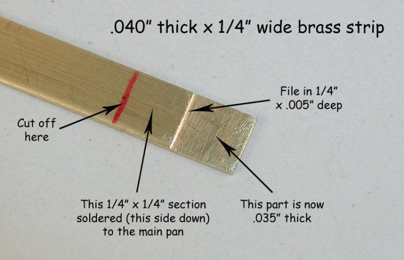
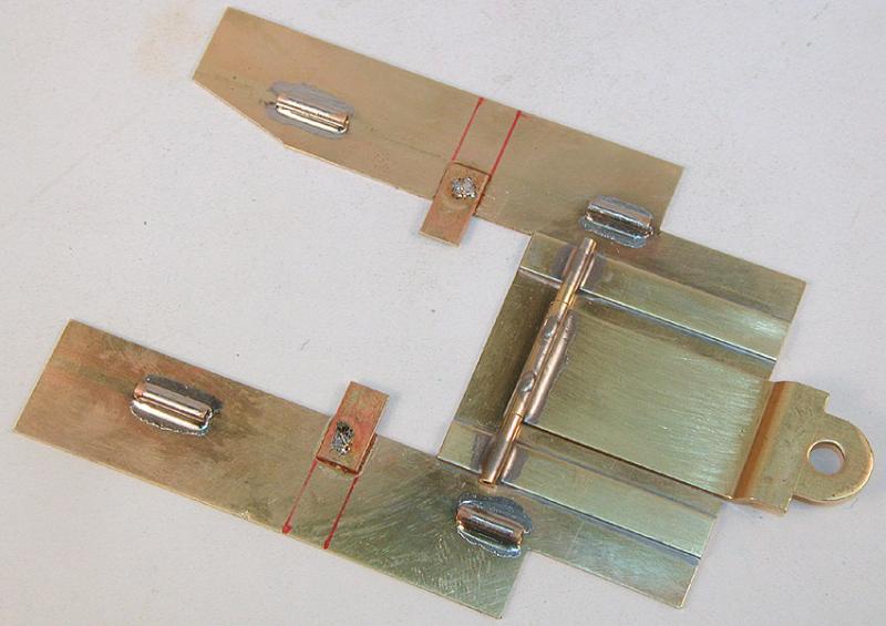
I dug out some .040" brass plate, and cut off a strip 1/4" wide and a few inches long. I filed a .005" deep "step" into the first 1/4" of the strip (checking with my dial calipers as I went), as shown here:
Bob Emott did something like this with piano wire when he built his own version of Sandy's Puzzle Pan. Now I have a one-piece "stepped" up-stop, no shim required! You could do this with .032" brass strip instead of .040", but it wouldn't be as strong, nor would it be as accurate a replica. An .032" up-stop on top of a .005" shim is .037" tall; fairly close to .040".
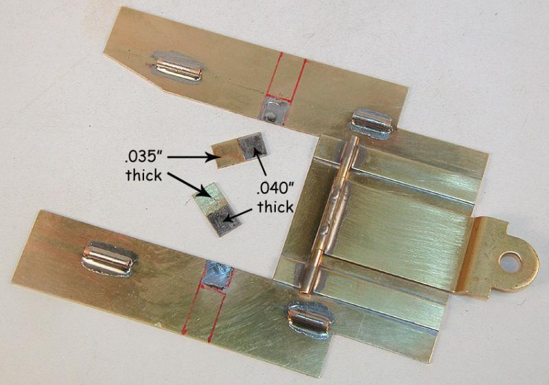
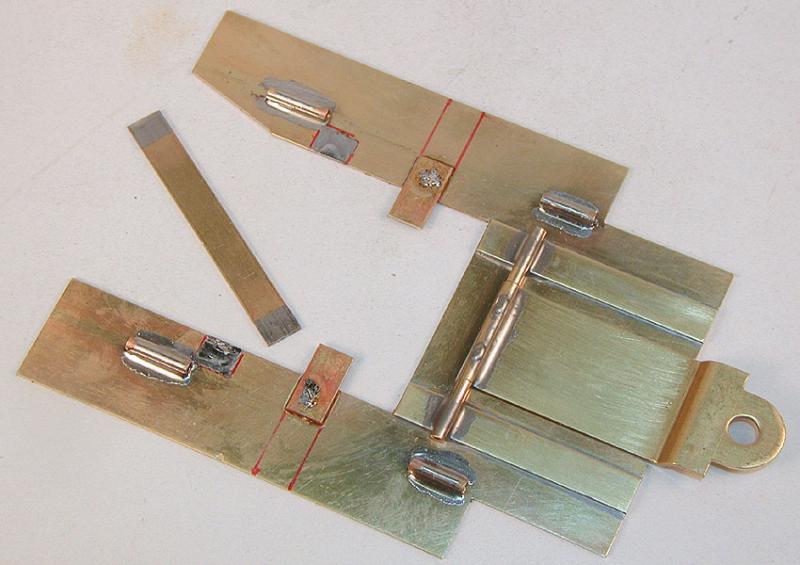
Tin the main pan and the .040" thick sections of the up-stops, like this:
Now solder the up-stops down, with the filed step on the bottom, carefully aligning them with the lines:
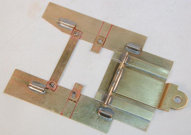
Cut a strip of .032" x 1/4" brass to length, place it in position, mark the outline with your marker then tin the parts:
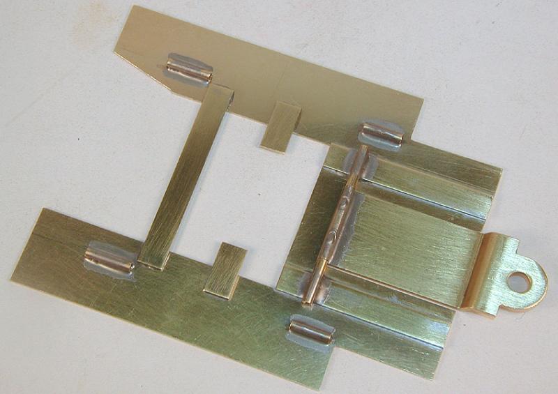
Now solder it down:
Now go back and clean everything up. Presto!
If you use jigs and mark everything carefully before you start slinging solder, consistent replication is easy!
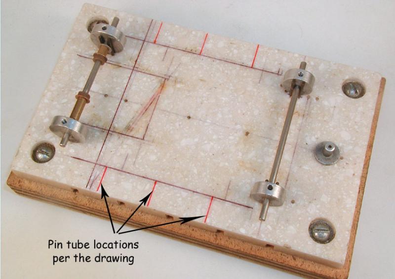
Okay, after that little side trip let's get back to installing the hinged body mounts. Mark your jig where the pin tubes will go:
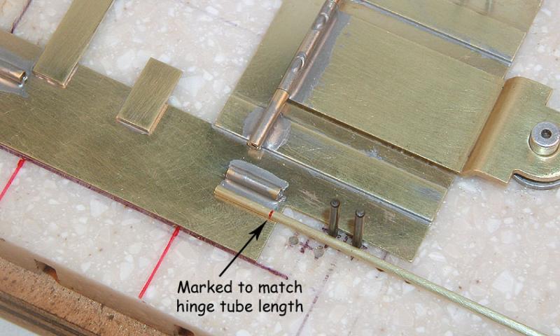
Set the main pan into the jig. Here we will make the forward pin tube, which has only one bend. Slide a piece of 1/16" brass (pin) tubing into the body mount hinge, and mark it to match the hinge tube length:
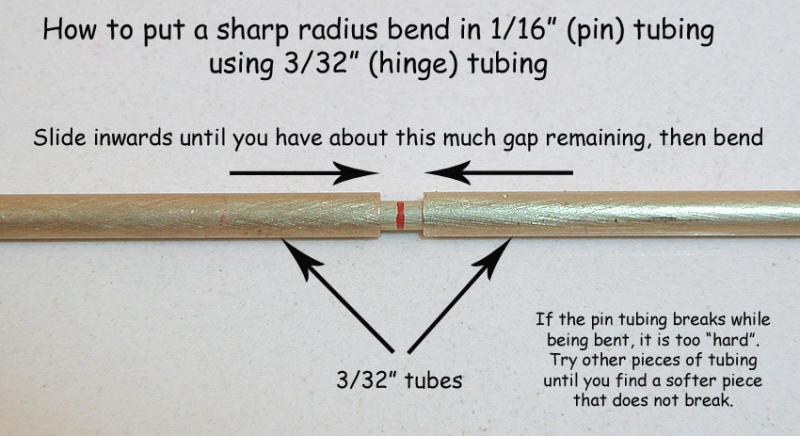
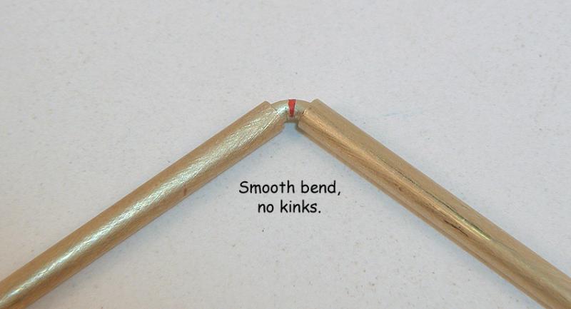
If you don't know this already, there is a real difference between "harder" and "softer" brass tube. You will likely have a great deal of difficulty bending harder brass tube successfully. Using two pieces of 3/32" tubing, slide them together over the pin tube until there is a small gap on either side of the mark where you want the bend to be, as shown. Now bend the pin tube.
If the pin tubing broke when you bent it, you're working with "harder" brass tube. Set that tubing aside and go find some "softer" brass tube that will accommodate the bend. If you already have softer brass tube (or when you find some) the bend will look like this:
Softer brass tube is not really all that difficult to find, in fact I had some in my materials box, laying right next to the stuff that broke every time I tried to bend it. Suppliers like K&S don't normally mark their product "hard" or "soft"; you will just have to search until you find some that bends without breaking.
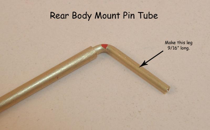
Now, on to the rear pin tubes, which have two bends. Make your first bend like this:
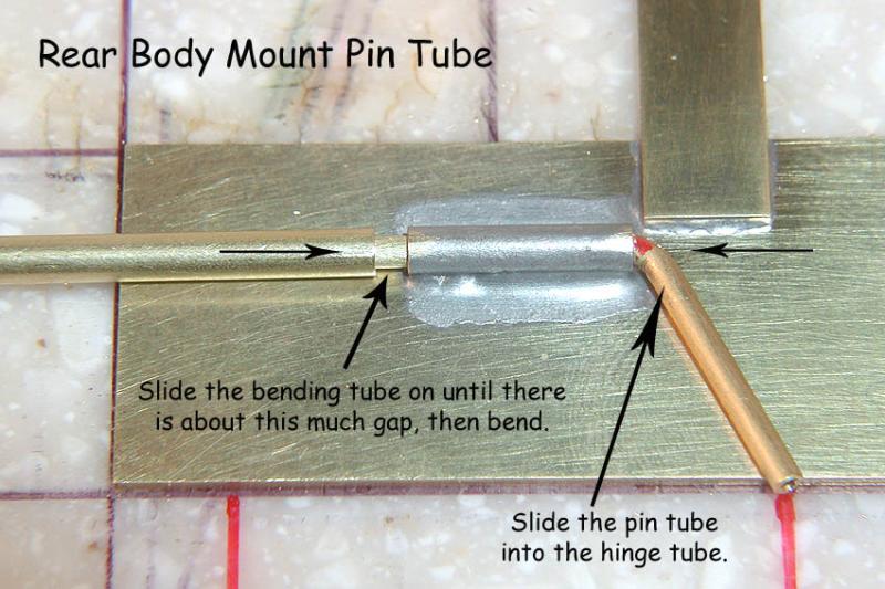
Slide the pin tube into the hinge tube on the main pan, and slide the 3/32" "bend" tube over the pin tube, leaving a small gap as shown:
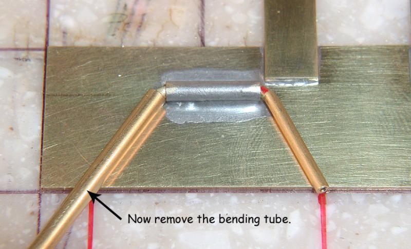
Bend the pin tube. Softer brass tube makes this quick and easy; harder brass tube makes this nearly impossible!
Repeat on the other side. Once you get this all sorted out, it should kook like this:
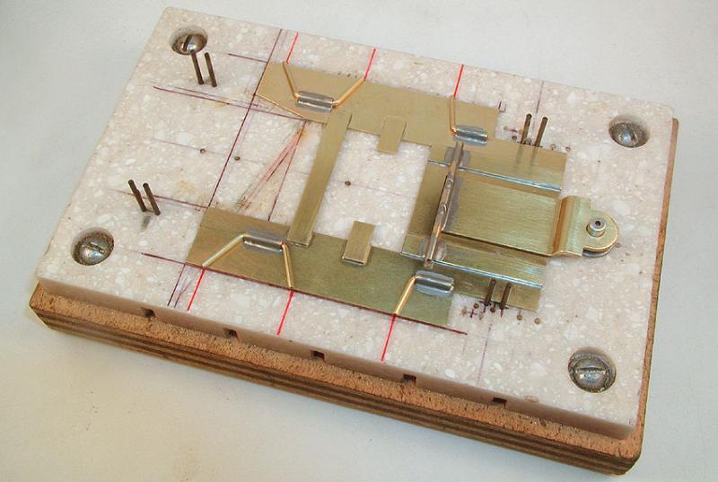
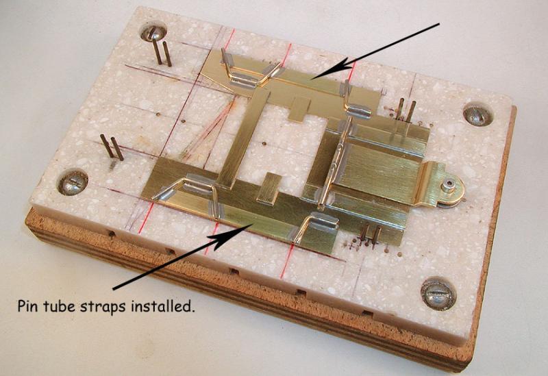
Almost done! Now cut some .032" x 1/4" brass strip to form the "straps" (they're not really pans) that hold the pin tubes together. I'm using .032" for three reasons: It's stronger than .016" or .025", the thickness forces the pin tubes to tilt upwards slightly which raises the pin holes in the body up a bit, and I'm thinking it's most likely what Sandy used on the original chassis.
At any rate, slip them under the pin tubes, about 1/32" inward from the main pan edge, and solder the pin tubes to them:
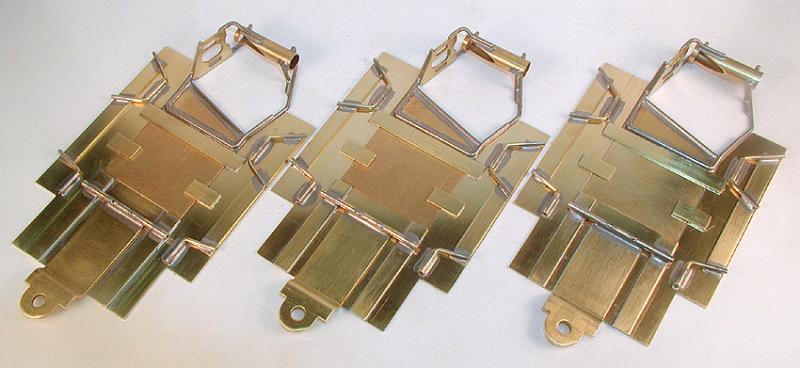
Clean everything up, and the hinged body mounts (and drop arm, and motor plate up-stops) are finished.
Next up, installing the body mount up-stops, attaching the motor plate and installing the front axle mount... (Click here)


