


Sandy Gross Puzzle Pan
Page 3
Drop arm, main pan and motor plate assembly
Now that we have our box of Puzzle Pan parts:

The next step is to assemble them!
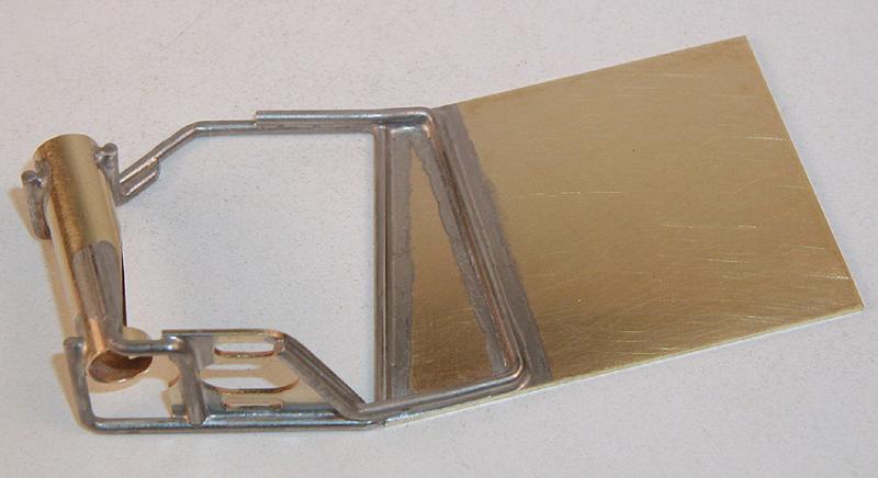
Pick out a main pan and some .032" x 1/4" brass strip. Lay the brass strip on the pan like this:
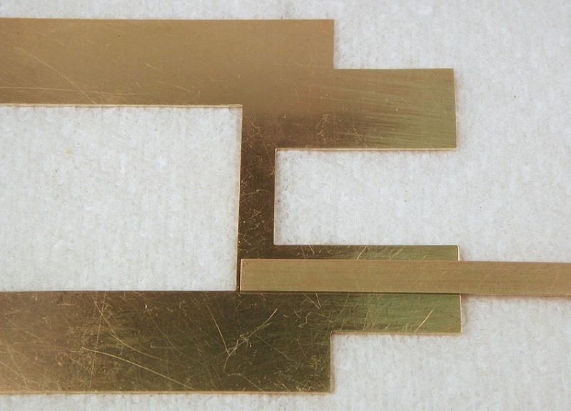
Take your Sanford Ultra-Fine marker (mine is red this time) and trace the edges of the strip like this:

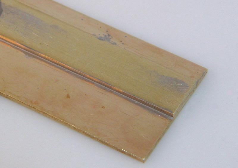
Do the same thing on the other side. Now tin one side on the brass strip (keeping the coating very thin) like this:

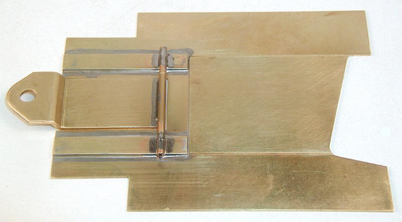
And also tin between the lines you traced on the main pan. Clean everything up and apply a bit more fresh paste flux, and solder down the strip. Do both sides. If you did it right it should look like this:
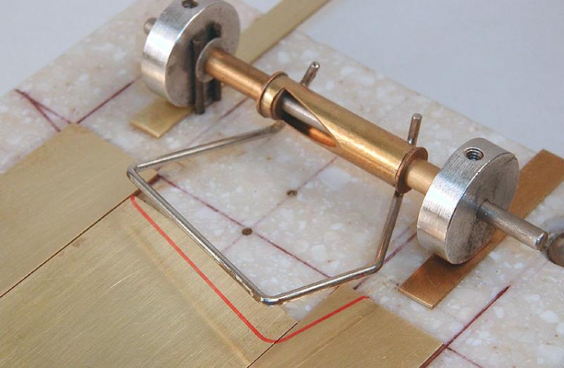
Later on you can clean up the excess solder with a bit of fine sandpaper. Now we need to solder a hinge tube on to the drop arm. I want it square to the centerline to a high degree of precision, so I'm going to whip up a mini-jig to hold the parts in alignment:

You may be thinking I'm simply going over the top here, but this little jig took about 20 minutes to make; less time than it takes to screw up soldering the 3/32" tube to the short drop arm, take it back apart and do it again. Plus, you can make multiple drop arms all exactly alike:

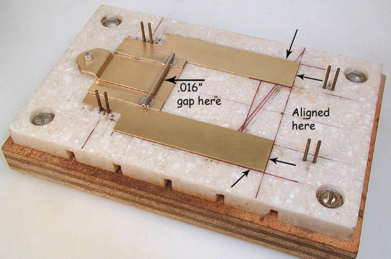
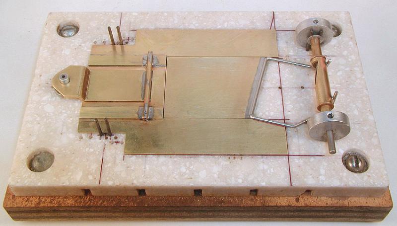
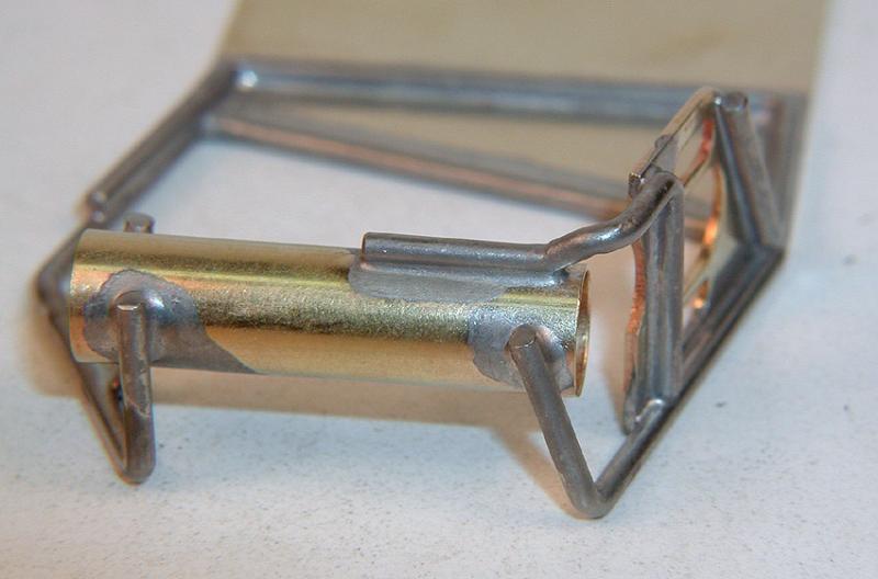
Now place the main pan on the chassis jig with (very important) the rear edges aligned with the marks you drew earlier. Set the drop arm over the guide post pin, and into the main pan, centered using .016" shims in the back and on both sides, and solder down the left and right hinge tubes to the main pan. This where all that work you put into making the drop arm and main pan exactly the right size pays off:
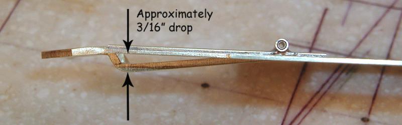
Turned over, it should look like this:
If you got the gap between the rear edge of the drop arm and the main pan correct, the drop arm should drop about 3/16" and stop. Sandy did not install a drop arm down stop on his original chassis; I guess he figured he didn't need it:
Now we move on to the motor plate. I cannot stress too strongly that you recheck the alignment of all the parts frequently to assure they remain where they are supposed to, and you don't end up having to take it all apart and start over!
Tin the motor box piano wire and recheck to assure the angles are still correct and that it still fits within the limit lines on the jig block. Soldering temperature heat has a way of making the bends in piano wire parts shift just a bit. It's easy to tweak them back into shape, but you have to remember to do it every time.
Once you've tinned and re-aligned the piano wire motor box, install the axle tube on a jig axle with spacers and jig wheels. Install your axle tube assembly in the jig block making sure the axle tube cutout vertical, align the motor box within the limit lines on the jig and solder to the axle tube. RECHECK to see all the parts are in proper alignment, then swivel the motor box around the jig axle and out of the way.
Place the main pan assembly on the jig block with the rear edges aligned with the marks you drew earlier. Lay the motor plate blank into the main pan and center it with shims. Insert .032" shims under the jig wheels to raise the assembly up, and swivel the motor box back down on top of the main pan and motor plate. RECHECK to see all the parts are still in proper alignment, and trace around the motor box with your marker:

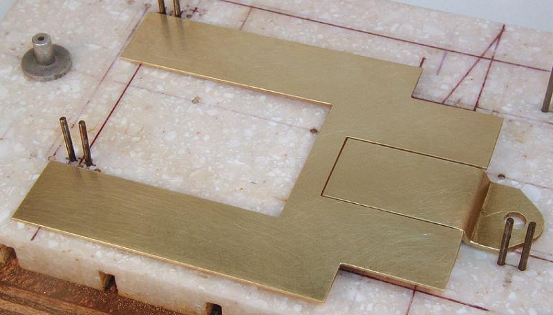
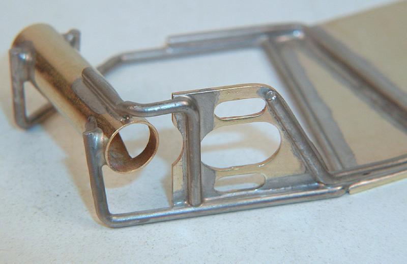
If you got it right, this is what you should see:
Now cut out the main pan and motor plate and reassemble. Here is what it should look like:
Put it all back into the jig block, pull the jig wheel shims, push everything down into place and it should look like this:

Now bevel (not more than half-way through the thickness) the lower rear edge of the motor plate, and solder the motor plate to the motor box:
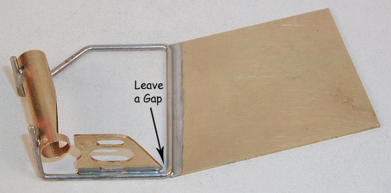
RECHECK the alignment before going any further! Now, screw the motor bracket to a jig motor, and install it in the motor box, leaving a small gap as shown:
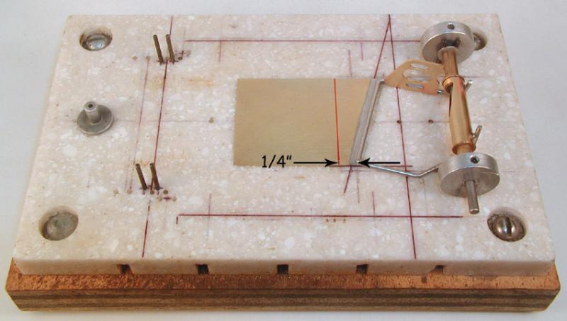
Put the motor plate assembly back into the jig, measure 1/4" from the front edge of the motor box and draw a perpendicular line across the motor plate:
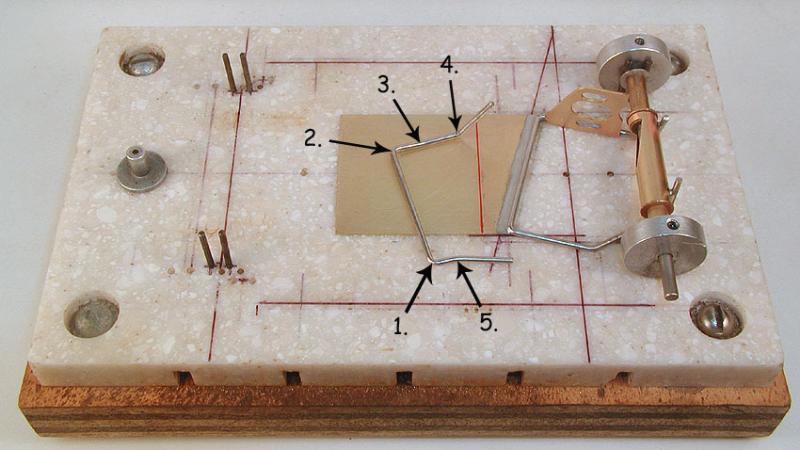
Now comes the fun part; making the motor box brace! The process is similar to making the motor box; measure, bend, measure, bend, etc. Start with a clean straight piece of 1/16" piano wire, measure 3/4" from the free end and make bend 1 with your wire bender slightly over 90 degrees. Using your pliers, reduce the angle to slightly under 90 degrees. This will relieve most of the stresses in the bend, so it shifts and changes the least when you tin the brace and then try to install it.
Measure 1-11/32" from the inside of bend 1, mark and make bend 2 slightly over 90 degrees, then reduce to slightly under 90 degrees; you get the drill. Measure 5/16" and 1-5/16" from the inside of bend 2, mark and make bend 3 at the 5/16" mark (only a few degrees) and cut off the piano wire at the 1-5/16" mark. Measure 3/8" from bend 3, mark and make bend 4 up (about 60 degrees) and slightly inward.
Go back to bend 1, measure out 3/16", mark and make bend 5 slightly outwards and slightly downwards, as shown in the photo:
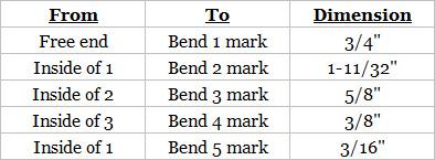
Here again are the "measure" dimensions between the bends in chart form:
Tin the brace and begin tweaking the bends until it fits like this:


Solder the motor box brace down to the motor plate and motor box. It should look something like this:

RECHECK the alignment of the motor bracket (it should be vertical) before going any further. Also check to see that the motor box and motor plate will lay flat on the jig block without rocking back and forth. Almost done! Now make and install the left (can) side "L" brace, and the motor bracket to axle tube brace.
What you see in the photo is my interpretation of what I see in the fuzzy photo I started with. Your interpretation may vary...
Suffice to say that the upwards jog in the brace right where it attaches to the axle tube is absolutely necessary for the brace to clear the set screw in the spinning gear hub, and nearly impossible to make without the "Z" bender I've been telling you about. I keep an unmodified "Z" bender to do these jog bends, in addition to the modified wire bender I use to make motor boxes.
From the jog bend I use an ordinary pair of pliers to make the 75 degree inward bend, and the wire bender to make the downwards 90 degree bend. Three different tools to make this brace. As I said, your interpretation may vary.
Having fabricated and installed the braces, trimmed the uprights, tinned the tips, and generally cleaned up the mess, your finished motor plate should look something like this:
Now go back and do everything twice more, and we will have gone from a box of Puzzle Pan parts to this:
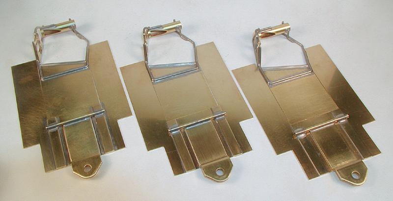
If you got everything right, the motor plate assembly should be able to move around freely (about .008" in each direction) inside the main pan; laterally (side to side) longitudinally (front to back) and allow the rear axle to yaw (move away from square with the chassis centerline) a degree or two in each direction . If you kept checking the parts alignment you should have no problems.
If the motor plate sticks or binds in the main pan, or simply doesn't move around enough, look for the point at which it is binding and carefully file the outside edge of the motor plate and/or the inside edge of the main pan until it does move freely; the gap between the parts must be straight and even along its entire length.
Next up, body mounts... (Click here)


