


Tony P's 1975 ARCO-USRA Winner
Page 4
I forgot a couple of things that need to be done. First is this .030” bullet proofing wire on top of the cross piece:

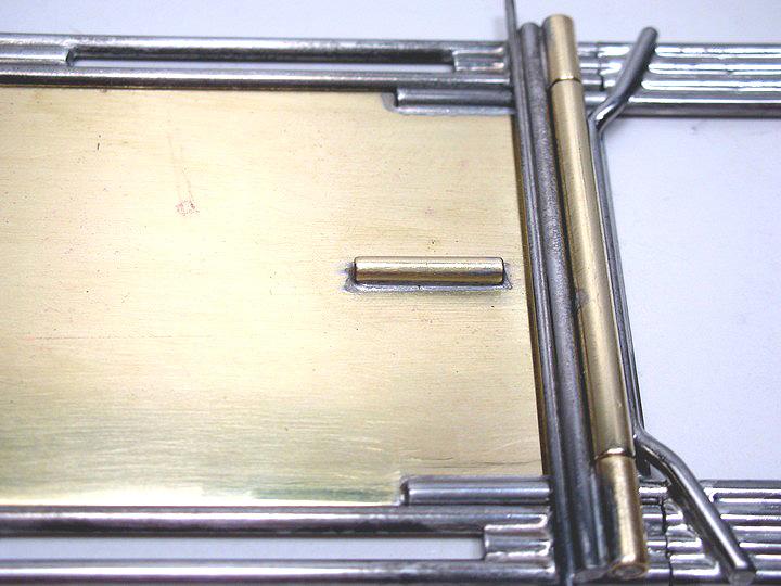
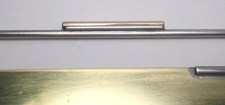
A 1/16” brass tube .360” long needs to be soldered in the center of the drop arm just ahead of the ISO pivot hinge:
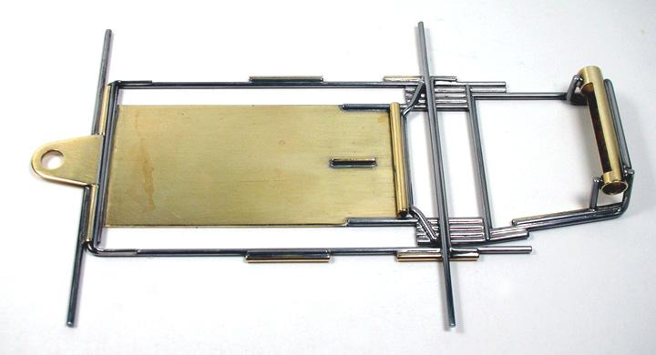
The pans are the same size as the currently available American Line:
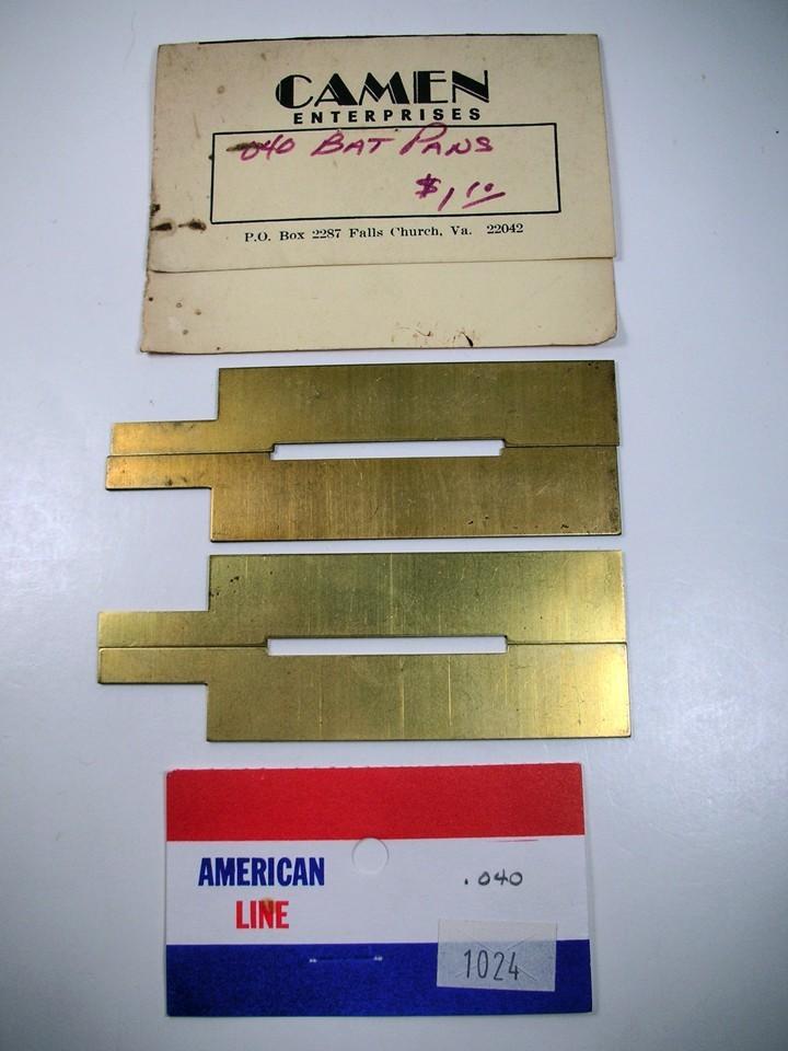
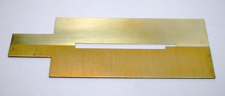
They need to be modified slightly. The notch hinge tubes needs to be lengthened toward the rear to an overall length of 1.965”:
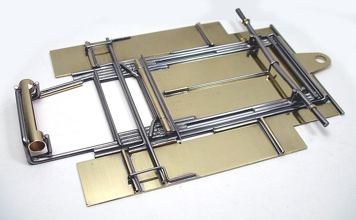
The plumber rail is .055” wire for lots of movement in the .062” ID pivot tubes. With the pans held in place the 1/16” brass pan pivot tubes can be soldered to the plumber rails:
A .030” wire is laid on top of the front hinge tubes for bullet proofing. After all the soldering the plumber rails will need to carefully straighten. The heating will cause them to bend dramatically:
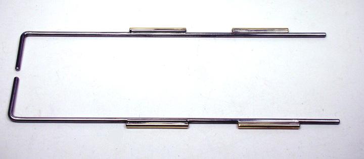
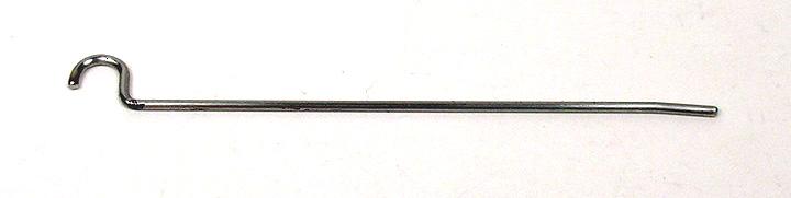
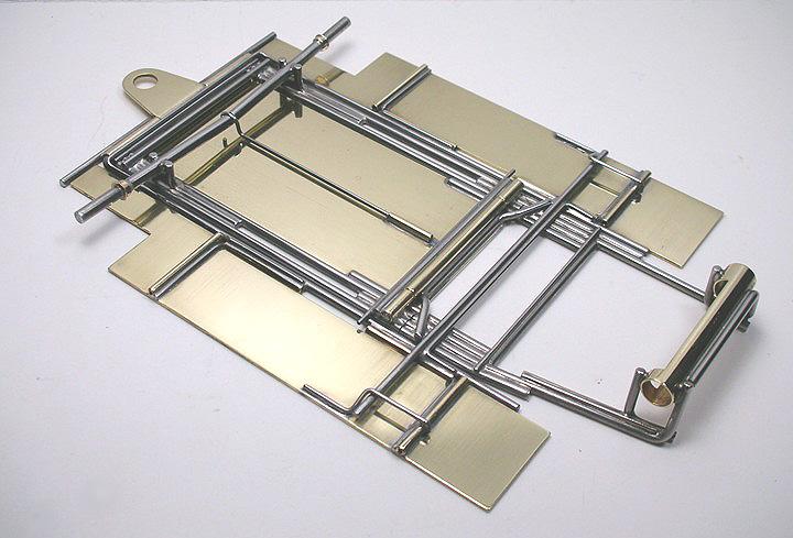
The plumber rails are tied together in the rear by a .055” x 3.060” long wire (that also severs as the plumber down stop and pan up stop). This is bullet proofed by a U-shaped .030” wire. Another U-shaped .030” wire attaches the front of the plumber. The front of it is kicked up a bit to match the similar bend in the plumber rail. Here are the pieces:
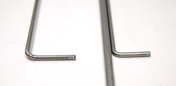
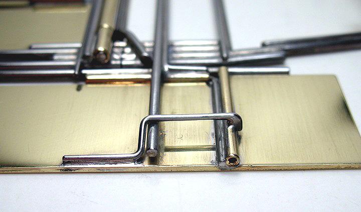
Here’s a close up of the bends that allow the plumber rail to lay down flat with the bottom of the chassis:
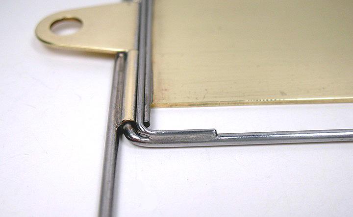
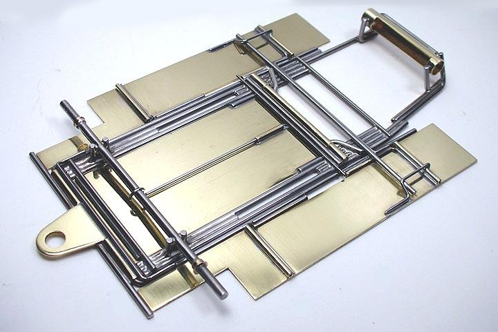
The rear U-shaped piece nestles down on top of the plumber and the pan hinge tube to further strengthen things:
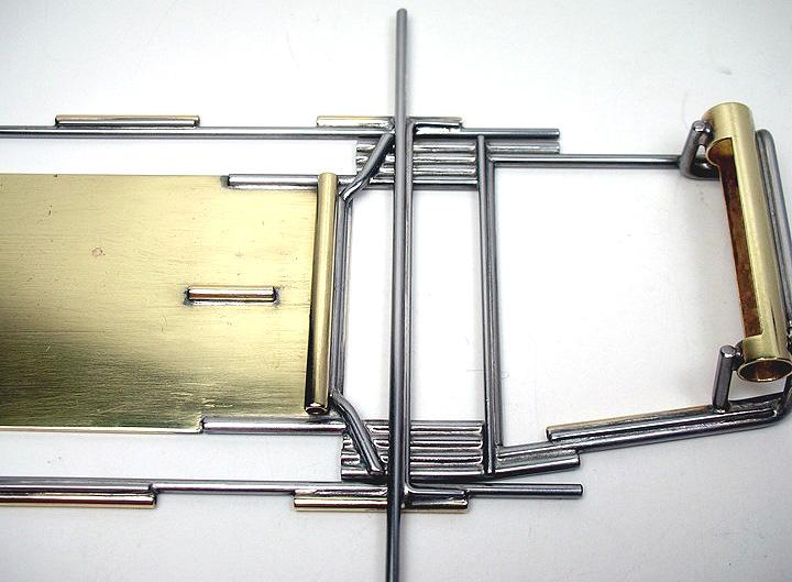
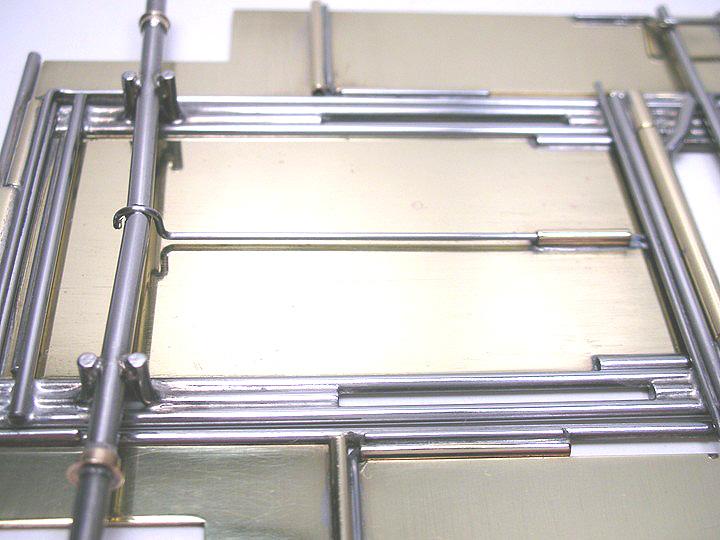
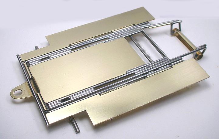
This is the finished plumber setup:
After the pans were installed a down stop was fashioned from .030” wire like this:
Almost done, but I needed to find out for sure what that 1/16” pin tube on top of the drop arm did. So I emailed Tony:
“The 1/16" brass tube soldered on top of the drop arm is for a .030" wire spring that slides into it and goes up to the groove
in the front axle????? If I put a straight piece of wire in for a spring it puts quite a lot of spring tension on the front end. Did you put a bend in the wire to raise it up to the height of the front axle and lessen the tension?????”
Tony’s reply:
“You are correct on the spring. I used that setup so if the glue was really thick we could remove the spring instead of bending it. In thick glue we never really used a spring...... I usually put an L-bend in the wire right at the axle that went straight up and looped over the axle. The other end we would just kink and press fit in to the 1/16th tube.”
My interpretation of the spring:
And the spring installed on the chassis:
The chassis is finished. Tony has graciously allowed me to send his original chassis to Steve Okeefe for one of his fantastic detailed drawings. (Click here) His “blueprint” will really help show how to build this cool chassis. Thanks for all your help Tony!


Next up is building the Hi Pro Turbo motor.
To be continued...


