


Tony P's 1975 ARCO-USRA Winner
Page 2
With Tony's original chassis safely stored in a zip lock bag on my work bench, it's time to build one of my own. I've never built an ISO before so the way I do things is just ONE way, not THE way.
Tony said this about his building process:
“I never did anything special to the chassis I ran like polishing it because I always felt it had to look like the ones I sold. I used to do a swirl pattern on the bottom with flexi-grit sort of like machine turning that evolved into Bob's (Bob Emott) cross hatch pattern when he stopped building. That hid any scratches and on a made it easy to tell who made it from across the room.”
“I learned from Bob Emott to always uses 60/40 at all areas where you need flex. So basically on a chassis like the iso I would use silver solder where the rails touched the axle tubes and the drop arm hinge. Everything else was 60/40, especially when soldering rails. He also taught me to always remove by scraping away with a tiny pointed file all the solder between the rails. By doing this the flex was the same side to side. I honestly do not think a lot of people knew this and built their whole car using staybrite which makes it stiffer.”
“I always felt that silver solder on things like the .063 hinge tubes broke easier than 60/40 because it had less flex. This I could be wrong on but I never had any problem using 60/40 there.”
So with that advice, here we go………
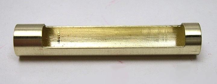
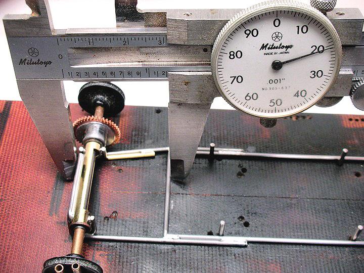
The measurements I'll provide were taken from the original chassis. I started with the rear axle tube so I could get it set up with a gear and jig wheels in my chassis jig. The tube is 1.2" long. The cut out leaves .1" full diameter on the gear side and .18" on the other side. I'm probably the only person who nibbles away at the cutout but it works for me:

The mess cleaned up with a file:
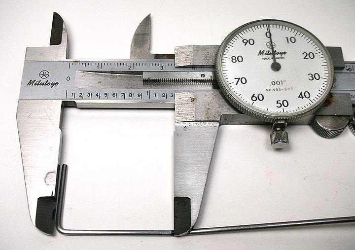
Next came the half rails. The gear side half rail is bent to set the motor angle. That bend is made at 1.3":
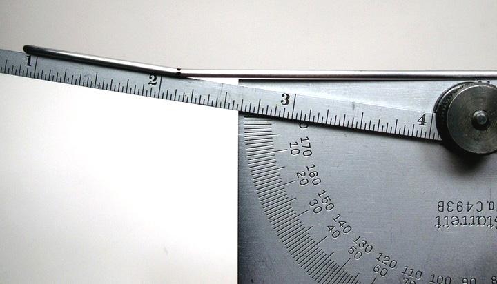
The angle for the bend is about 8 degrees:
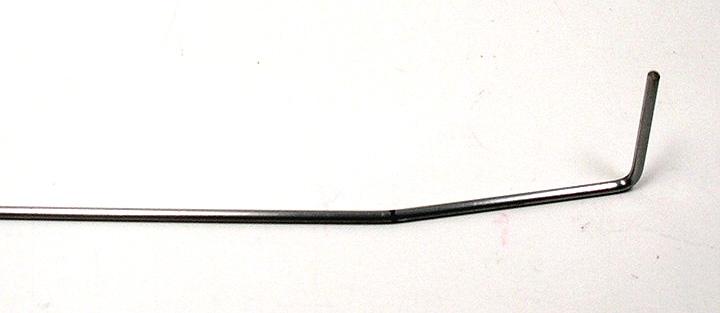
The finished half rail left extra long to aid in alignment in the chassis jig:
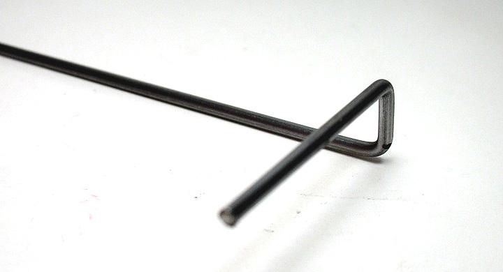
The other half rail is straight but it does have a neat bend on the back side of the axle tube at the axle centerline:
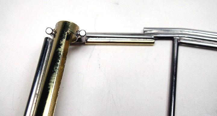
Both half rails get an "L" shaped brace soldered to the front of the axle tube:
Tony offered this advice, “We found by keeping the rail under the endbell as single unit and making the inner brace point to the rear the cars would go punched up the donut. Turn the inner brace around and the car wouldn't. It was a well kept secret for along time and one of the ways we could tune the Iso chassis for bite.”
A cross piece is placed between the half rails at 1.2". I set mine at 1.22" for a little extra motor clearance. The half rails are cut to 2.2” measured from the same location:
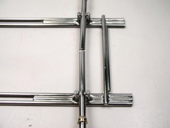
Here the main rails are installed along with the 3/32" ISO pivot tubes, a bullet proofing piece of 1/16" wire and the .030" plumber up stop wire in front of them. The center of the ISO pivot tubes are .75” from the rear axle centerline:
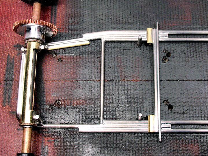
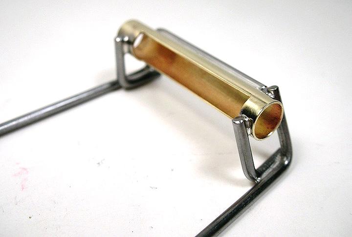
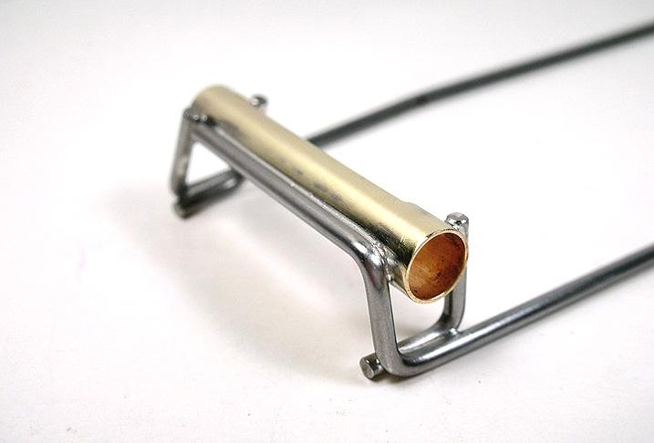
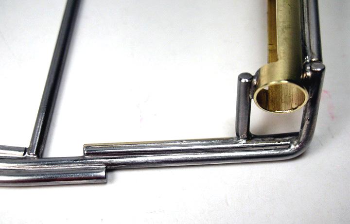
Tony used a piece of 1/16" brass tube .670” long to space the motor away from the half rails:
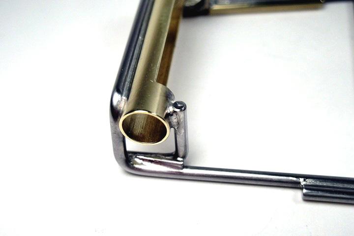
He placed a piece of .030: wire on top of the joint to bullet proof it:
He placed another on top of the other half rail brace:
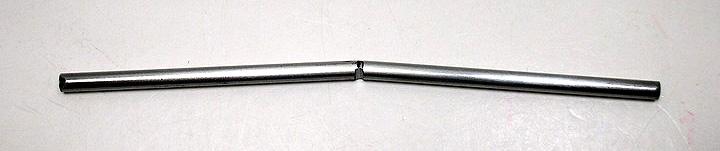
The front axle is a JK extra long 3/32". A small notch is ground in the middle and the axle is bent to a 7-8 degree angle for a negative camber effect on the front wheels:
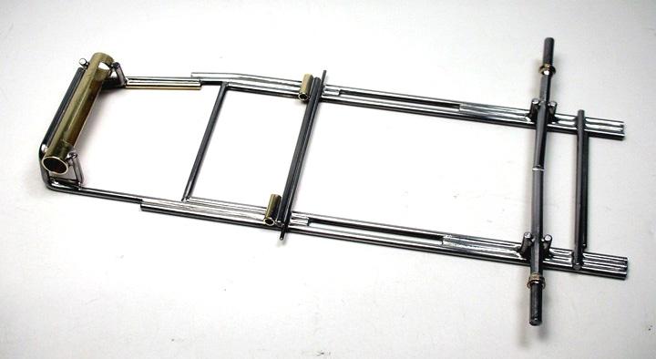
Here the axle is installed in simple "L" shaped uprights. The rear upright is .6” long. The front upright will be cut off flush with the main rails. The wheelbase is 3.8”. Also installed is the ISO front axle down stop:
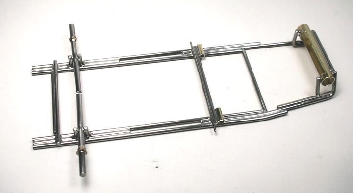
The center section is finished and waiting to be cut in half! Here's what Tony said about this process, "These cars were built, hinged and then cut in half for the iso movement right before pans were attached. Not sure how others did it.."
I'm not that good! I'll be cutting it in half now so I can clean up my cut:
Next up, cutting the center… (Click here)


