The First Anglewinder
Page 2
In case it isn't painfully clear already, this project is progressing in incremental, frequently minuscule steps. There is a reason for this; in addition to cobbling together a simple mechanical copy of this improbable design, I am trying to reproduce, from photographs alone, Gene's creative process, and his technique.
This may come across as ugly. blobby solder joints, or maybe wondering why Gene "did what he did, the way he did it". No matter, my goal is to have you look at the finished chassis and see the same things we now old pharts saw in 1968.
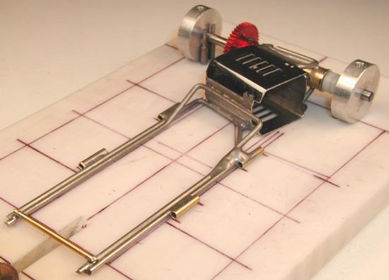
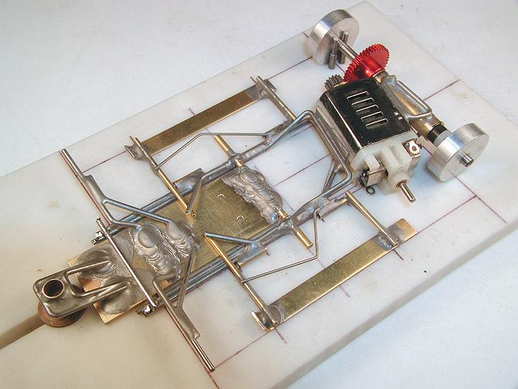
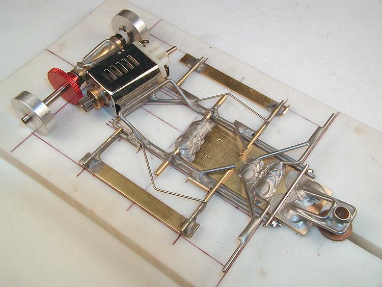
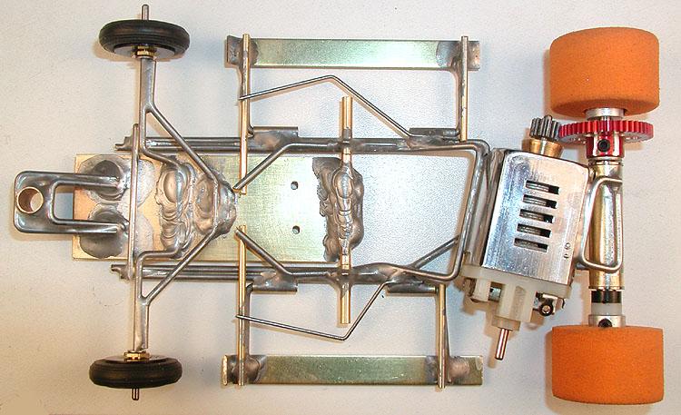
Center section with side pan hinge tubes attached. Scaling from the photographs, I don't think any two tubes are exactly the same length! The two rear tubes are, of course, not located directly across from each other. The left rear tube actually hangs out in space; attached to the chassis only by a blob of solder.
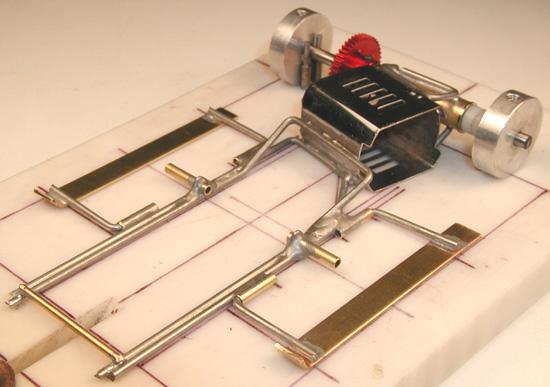
Side pans and drop arm hinge tubes attached. The body mount pin tubes, piano wire down stops and springs, are a whole 'nother building session! The drop arm hinge tubes are braced with .032" piano wire that runs forward along the top of the main rail behind the tube and then is bent up and over. Here they are hard to see because they are mostly buried in solder!
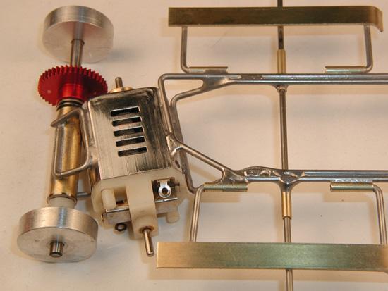
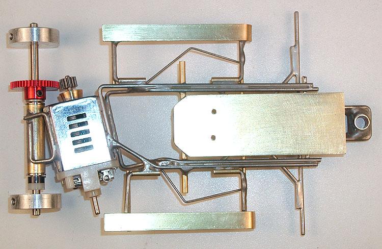
Bottom view showing relative positioning of the various parts including the motor shaft pointing at the rear outboard tip of the left side pan (compare to the photo of the original). Most of what takes so long is assuring the parts fit together in such a way as to look exactly like Gene's chassis, no matter what direction you view it from. Another surprisingly big time consumer is working the solder joints so they replicate the original work as closely as possible.
Next up: Finish the side pans.
The larger of the two halves of the chassis is now complete.
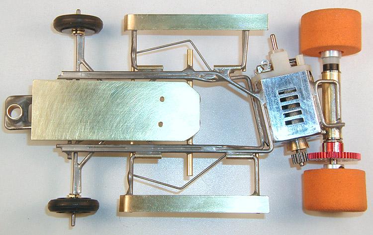
With the addition of the pin tubes, upstops and springs, the chassis is really beginning to resemble the original.
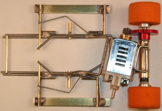
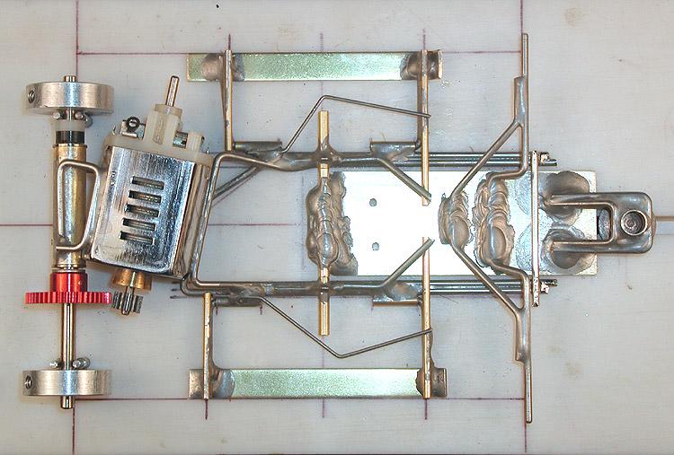
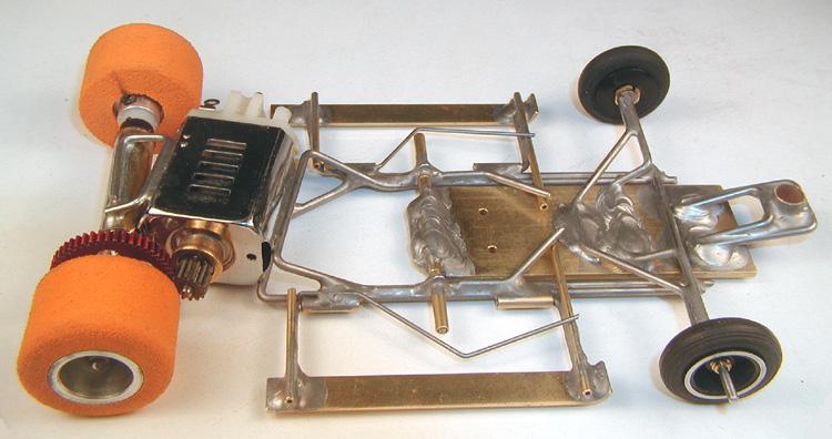
Top view showing all the parts in place. As with the side pan hinge tubes, no two corresponding parts (left side / right side) are exactly the same length, shape or alignment!
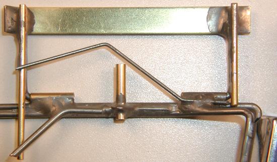
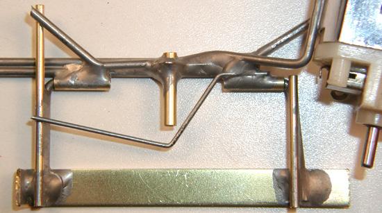
Right side pan, photo left is forward. Front pin tube sits more or less on top of the hinge arm, but rear tube is mounted slightly aft. Side pan spring apex is well forward of the drop arm hinge tube. Again, an effort was made to reproduce the size, shape and location of the solder blobs.
Left side pan, photo left is forward. Front pin tube sits forward of the hinge arm while the rear tube is at a distinct angle to the arm. Side pan spring apex is about even with the drop arm hinge tube. Note how the spring wire is literally soldered to a solder blob at the rear pan hinge tube!
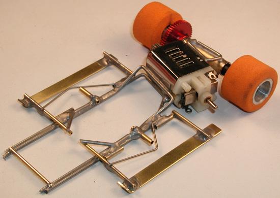
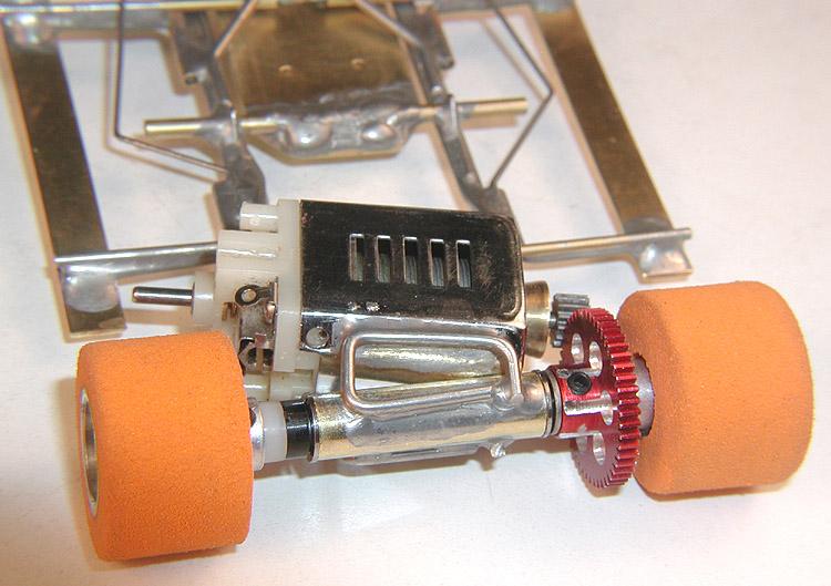
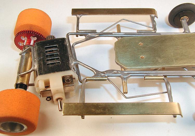
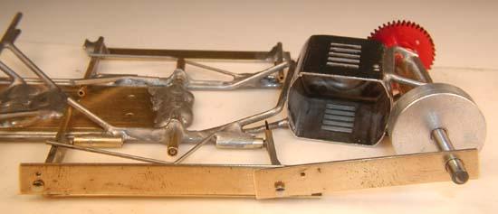
Left quarter view. While Gene may have used a Dremel tool in the construction of his original chassis, he didn't use it to cut the piano wire! As far as I can tell, all the cuts have been made with good old fashioned side cutters.
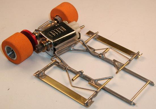
Right quarter view. That brass cross piece at the front of the chassis is temporary for construction. It must be removed while the drop arm / front axle assembly is being built in place. Once done, this crosspiece, in 1/16" piano wire, will be the last piece to be installed on the
chassis.
Next: The drop arm.
In my attempt to reproduce an exact copy of Gene's work, I have discovered that the drop arm/front axle assembly is a maze of odd dimensions and relationships.
This last major section of the chassis sets the guide lead, the wheelbase and the track clearance for the front end of the car. While I'm getting those things right, there's the distance from the guide post to the front edge of the drop arm slab, to the front axle, to the drop arm hinge, and the list goes on. It's a complicated puzzle.
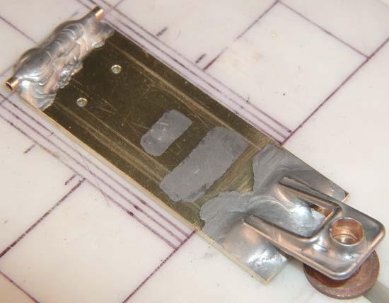
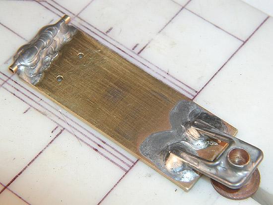
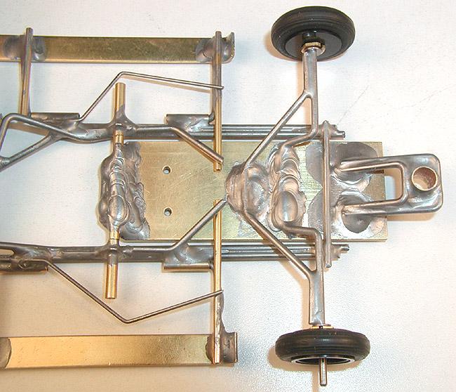
The drop arm with its three piece guide tongue attached to the drop arm slab by nothing more than blobs of solder. Note the open space on either side of the guide post tube filled in with webs of solder, not unlike a soap bubble. Gene seems to have been using construction techniques, like filleting and puddling, which are more akin to welding than soft soldering. The two small patches of solder in the middle of the drop arm are where the front axle and its brace will be attached.
Those two "Husting holes" in the drop arm serve no purpose I can imagine or have ever been able to deduce. Even Gene does not remember why he put them there! Anybody care to guess?
The hinge tube is the only common looking part on the drop arm. The drop arm hinge on this chassis is more properly called a main chassis hinge, as it is the only thing that holds the two halves of the chassis together. With as much solder as it has on it, there's no need to worry about
it coming apart!
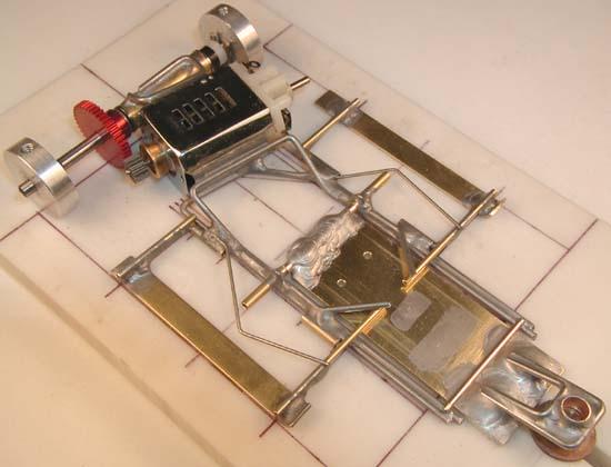
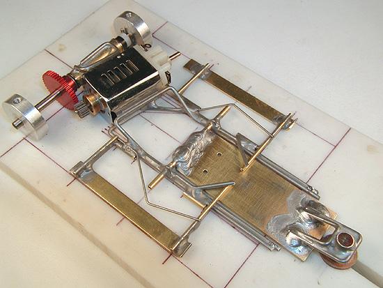
Chassis with the drop arm set temporarily in place. The only thing left is the drop axle, its brace, and the permanent front main rail cross piece. The depth of the "U" shape in the drop axle will have to be determined by trial and error, in order to get the correct angle by which it is mounted on the drop arm. You can bet there will be a few trials before the right dimension reveals itself!
Next (and last): The front axle.
The solder joints on the drop arm had me puzzled for a while. All the other joints are in relatively low mass areas; rails, tubes, and the thin wall motor can for example. They could be soldered with a regular iron such as a Hakko throttled down to a low temperature. But the drop arm joints would be in a high mass area; the 1/16" thick drop arm slab.
I don't need to tell you how much this changes the approach to the work! It took me longer than it should have to figure out how to duplicate the appearance of Gene's soldering work on the drop arm. I don't think he had any "magical" techniques; they were just...different.
As you may know by now, Gene was a drag racer (full size and 1/24 scale) before becoming involved in slot (road) racing. He and his friends all built their own cars, and you can bet they didn't solder the full size car parts together; they were welded!
It occurred to me some of the solder joints on this chassis. Like the left rear side pan hinge tube, that seem so poorly thought out, would not be given a second thought had they been welded instead of soldered.
Soldering is a process of "gluing" things together, whereas welding fuses the base metal; the welding rod is made out of the same stuff as the metal being welded, and becomes part of the metal being welded, there is no "glue".
Two of the many techniques employed in welding are called "filleting" and "puddling". Both of these techniques seem to have been used on this chassis except that they are done with solder and not welding rod. This goes a long way to explain what we see and describe as "blobs" of solder.
But we were talking about the drop arm... The photos of the drop arm that I posted yesterday show two different approaches to soldering parts on to the 1/16" brass slab. The drop arm hinge tube joint, which is seriously "blobby" and is a reasonably good facsimile of Gene's work, is the second approach. The guide tongue attachment was my first attempt and the one I was only marginally satisfied with.
To solder down the guide tongue, I used my regular Hakko iron throttled down to a low temperature, and tinned both the piano wire parts and the drop arm slab before assembly. To produce an extremely thin tin coat on the drop arm slab, I used a touch of soldering acid.
The guide tube joint went okay, but when I tried to solder the guide tongue to the the slab, the mass of the slab just sucked the heat out faster than the iron could produce it, and I got nowhere. If I allowed the iron to heat soak the slab up to soldering temperature, I could not reproduce the "blobby" look I wanted; the solder just flowed everywhere on the hot slab! The results are what you see in the photo I've already posted.
The drop arm hinge tube was soldered differently; I turned the iron up as high as it would go (1100 degrees) and used the iron as if it were a welding torch, and the solder as if it were welding rod. Those results speak for themselves; blobby!
After I posted the photos, I got to thinking I might be able to do a better job on those guide tongue joints, and when I looked again at the photos of Gene's work, I knew I had to go back and fix mine. When Gene soldered his guide tongue to the drop arm slab, the solder fillets (which we call blobs) remain in the immediate vicinity of the joint; they do not extend (flow) all the way out to the edges.
It took me a whole day to get up the resolve to re-do the guide tongue joints.
I managed to unsolder and remove the guide tongue assembly in one piece, then I cleaned every trace of solder off the front end of the drop arm slab. I did not touch the drop arm hinge tube joint.
After putting a thin coat of oil on the drop arm slab, I re-jigged everything, turned my iron up to 1100 degrees, and soldered the guide tongue down as though I were welding it.
Using the excessively hot iron to maintain a localized but highly fluid puddle of solder, I drove it or drew it where I wanted it to go, feeding in small amounts of solder as I went. The oil coating on the slab helped prevent the solder from flowing wherever IT wanted to go
I'm happier with these results:
NOW... I can move on to the front axle.
With the installation of the front axle and its brace, the chassis construction portion of this project is finally complete.
Wire bending, fitting and soldering the front axle and brace was done using techniques already described, so there's not much need to elaborate on how it was done. This time I'll just let the photos speak for themselves. Enjoy!
This has definitely been the most complicated project I've done in a long time, and its certainly had it's share of frustration and fun! I've even learned a new trick or two, and re-learned how to make blobby solder joints.
One of the primary goals of this project has been to produce an absolutely accurate and precise copy of Gene Husting's original chassis. Toward that end, I have expended a great deal of time and effort, significantly more than I had originally anticipated, to replicate every detail, including imperfections, misalignments and irregularities.
Philippe has made it plain to me that for display in the Marconi Museum, he intends to mount the ORIGINAL body from 1968. The original body has, of course, the original pin holes! In keeping with the primary goal, it follows that the position of the body mount pin tubes on the replica chassis MUST match the positions of those on the original chassis, to a high degree of precision, so that the original body will fit!
For months I wondered how I was going to do this. The location of the pin tubes would have to be accurate to within a few thousandths of an inch, well less than half the diameter of a mounting pin. As the project neared its completion, I realized I would need dimensions taken directly from the original; as it had become obvious the photographs were far too imprecise.
I decided to email Gene Husting again, and ask him to have Philippe measure the original chassis and determine the position of the rear tubes relative to the rear axle, and the position of the front tubes relative to the rear tubes. Gene was kind enough to do this right away, and then I had the precise dimensions I needed.
How well would they match up to the now completed replica, which was built using the dimensions I extracted from the photos? As it turns out, it was close, but no cigar! I was going to have to shift, by twenty to thirty thousandths, the position of three of the four pin tubes, the left front side pan hinge tube, and the left side pan down stop. Before I was done with that, I also had to replace the left side pan spring, as it was now too short!
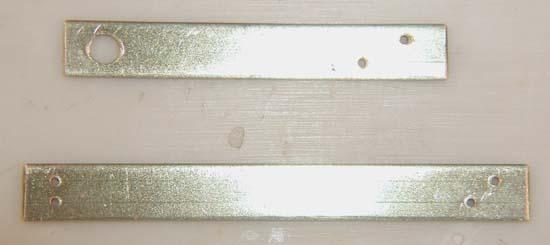
So I made up two fixtures, using the dimensions Philippe had supplied. One for the rear axle to rear pin tube, both left and right, as the two dimensions are very different, and another for the rear pin tube to the front pin tube, again left and right:
Using the two fixtures, I began moving things around, first on the right side (the easier of the two):
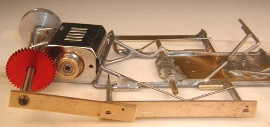
And then on the left side, which included moving the front side pan hinge tube and down stop, and replacing the side pan spring:
Now the original body should fit exactly!
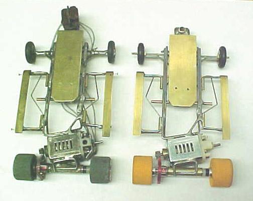
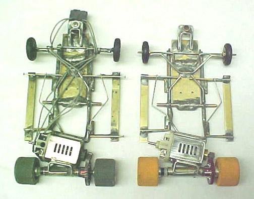
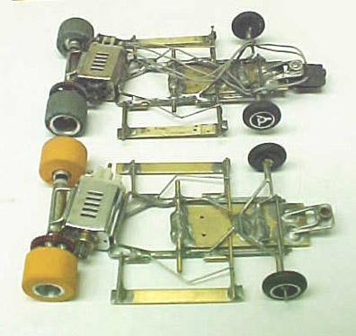
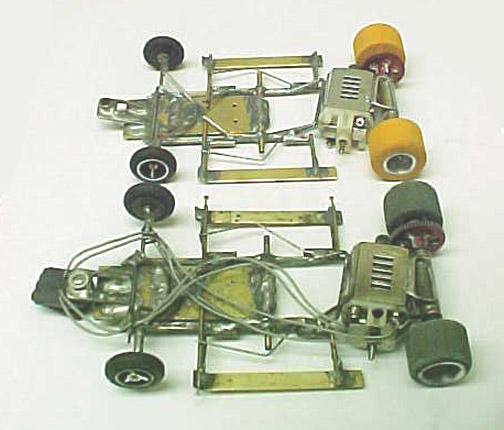
At this point I considered the project complete, and sent the chassis off to Philippe. I asked him to take a few photos of the two chassis side by side, and he was kind enough to oblige. These photos belong to Philippe de Lespinay, but I doubt he will mind my posting them here:
Turned out well, ya think?


