The First Anglewinder
A photocopy perfect replica of Gene Husting's revolutionary 1968 design
by Steve Okeefe
Updated March, 2013
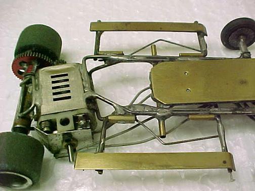
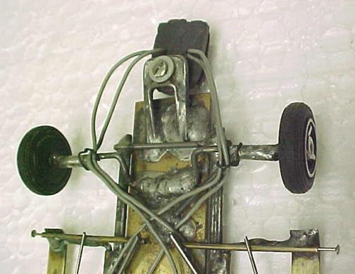
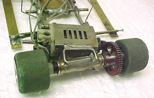
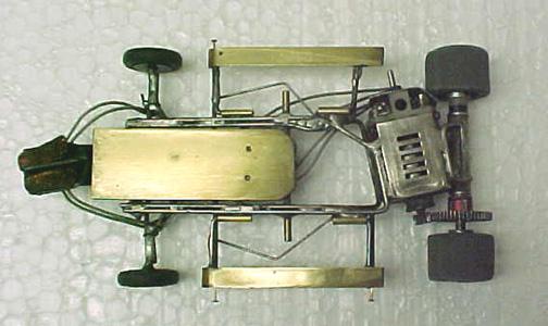
This is a "reprint" of a series of posts I made on The Old Weird Herald several years ago documenting my construction of a "photocopy perfect" replica of Gene Husting's revolutionary 1968 design. When I say "photocopy perfect" I mean right down to the misaligned parts and blobby solder joints you see in the photographs of the original chassis.
Those blobby solder joints were the subject of some discussion, and it was decided that the build should include them instead of "neat and clean" solder joints similar to most of the legendary builders of the day (whom I generally try to emulate). As it turns out, duplicating those blobby solder joints was one of the more challenging parts of the effort!
The chassis itself was built for Philippe de Lespinay, and is currently on display in the Los Angeles Slot Car Museum (LASCM).
To get started, the first pro race that featured 1/24 scale cars with anglewinder drive was held in April, 1968 at Classic Raceways in Santa Monica, California. Gene didn't enter this race but he did report on it in an article that appeared in the July issue of Model Car & Science magazine. The anglewinder drive worked so well that by the time this article was published only three months after that race, inline drive pro racing slot cars had all but disappeared...
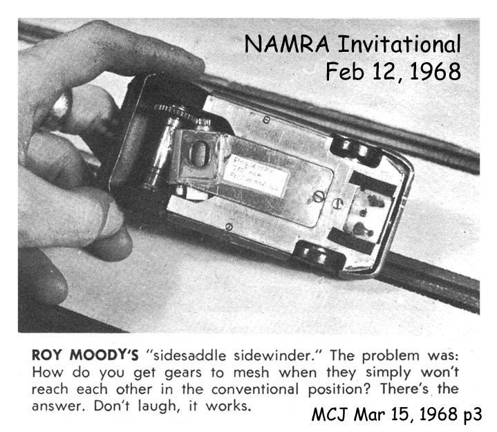
Gene Husting did not "invent" anglewinder drive; Roy Moody built a 1/32 scale Mabuchi 26D anglewinder and entered it in a NAMRA race on Charles Cressi’s LIMERA club track in February of 1968. Sandy Gross, Howie Ursaner and Pete von Ahrens were all at that race, along with Roy Wong, Fred Correnti and Jose Rodriguez. The photo below is from an article written by Sandy which appeared in the March 15 issue of Model Car Journal. Roy’s car, driven by Chip Chisena, placed second in the semi.
At least seven top builders and drivers saw Roy Moody’s 1/32 scale anglewinder in February, but it was Gene who was the first to apply the idea to 1/24 scale pro racing slot cars, and that earns him a permanent place in the slot car Hall of Fame.
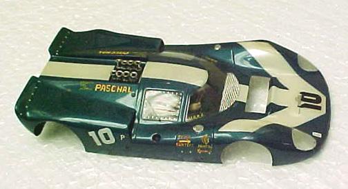
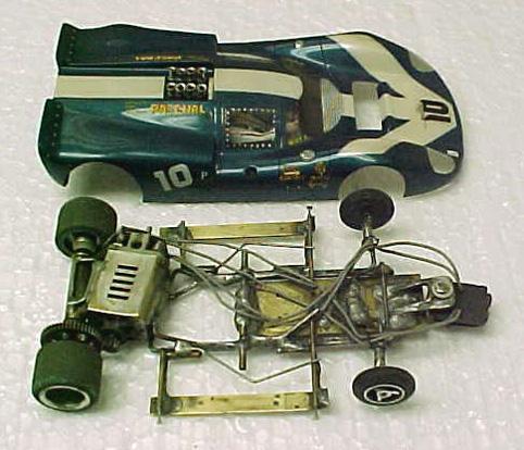
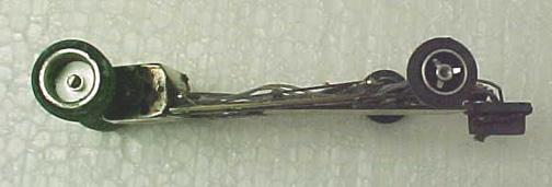
Because I had no information about the chassis except old, grainy magazine photographs, I asked Philippe and Gene to provide a few clearer photos of the original chassis. These photos belong to Philippe de Lespinay, but I doubt he will mind my posting them here:
These photos are much better than the magazine photos, but still all I had to work with.
Now, on to the posts!
Motor and axle tube:
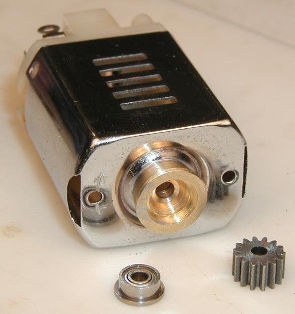
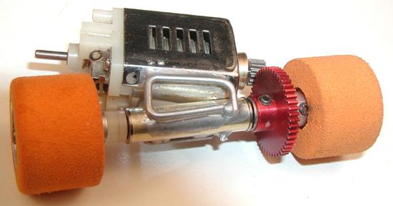
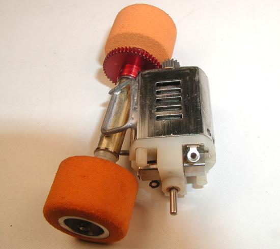
Having discovered that the funny shaped can bushing that appears in the photos of the original car is not a bushing at all (it is a ball bearing carrier), I needed to make one in order to move things along.
Once I separated the old bushing from the can, I carefully filed the hole to center it (it was .005" off vertical center), reamed it out to 5/32", and chamfered the outside edge.
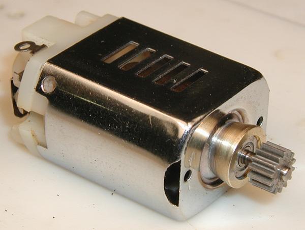
After scrounging up an old ball bearing, I turned the carrier out of brass stock to fit both the bearing and the can, as I presume Gene did. To avoid having to go out and buy the "right size" drill bits for a one time use, I had to grind a very small tool bit to cut the inside diameters!
I silver soldered the carrier to the end of the can, and cleaned up the whole thing with a toothbrush and some Comet cleanser. Now we are ready to begin piecing together the motor/axle bearing tube assembly.
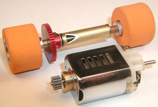
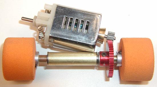
With the axle tube cut to one inch, tires spaced out to three inches, and axle tube and gear positioned to closely match the photos of the original car, I cut a small notch to clear the motor.
Given the 7/8" tires and the correspondingly large 64 pitch gears (14:48), this rather small notch appears to be all it takes to accommodate the can.
Next up, can braces with lots of solder!
I see the can braces as one of the most critical steps in building this chassis, for two reasons: First, the braces "fix" the axle tube in relation to the motor, and therefore the whole chassis, in terms of axle height, motor angle, gear mesh, etc. Get these relationships wrong and nothing else will quite fit or work right.
Second, this is where I get to find out if I'm going to be able to "copy" Gene's soldering technique well enough to do justice to this class "A" reproduction. I was concerned this was not going to be as easy as I originally thought!
Cutting and bending the braces took several tries before I got the lengths and angles even close to "right". I had to put down my Dremel and wire bender, and go back to cutting and bending with ordinary pliers! Some bends in these braces seem to have wider radii than others, so I tried to copy them exactly as I saw them in the photos.
Getting "blobby" solder joints turned out to be a matter of turning the iron temperature down to the point where it just barely melts the solder. That way, you can glob it on and it pretty much stays where you put it. Also, it doesn't melt other nearby solder joints!
Making solder to stick to this chrome plated Pactra can turned out to be the hardest part! I don't know what Gene used, but paste flux is nowhere near active enough to etch the plating, and hot acid flux spatter quickly begins to stain the chrome; neither method was going to work! I had to gently grind away the chrome plating in those areas I wanted solder to stick, just enough to reveal the steel, but no more. Then I tinned the areas where the can braces and main rails would be attached.
After I got my blobby soldering technique worked out, I finished the can braces with a small flourish by copying the two tiny solder blobs on the top of the can. First however, I had to scrape the chrome plating off those two tiny spots to get the solder to stick! You can see them near the screw hole, between the brace and the cooling vents.
Next up, main rails.
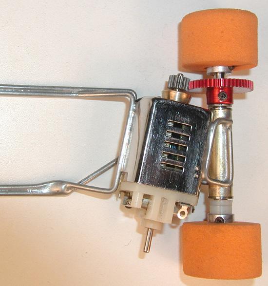
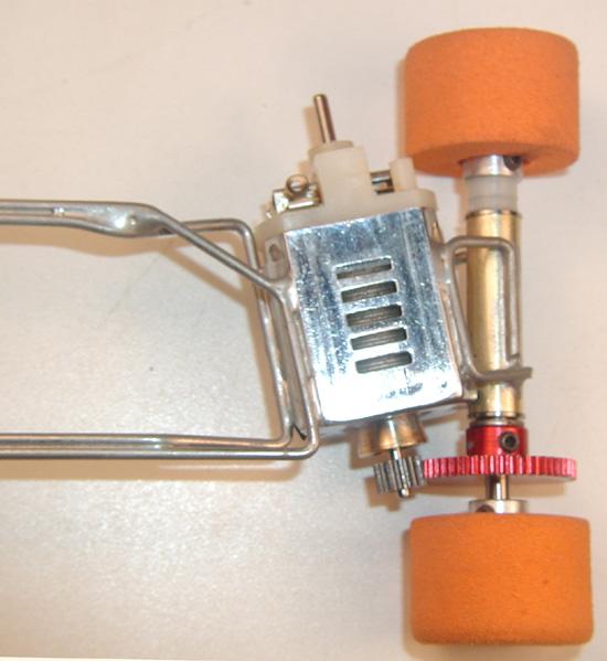
Gene Husting's revolutionary design had a number of unique features beyond the odd motor mounting angle; not the least of which was the fact that the main rails were not attached to the rear axle carrier in any direct way! Like the designers of many state-of-the-art full size race cars, Gene used the motor itself as a component of the chassis, with the rear axle tube soldered to one side, and the main rails soldered to the other.
Eventually, after being soundly trounced at every turn, the rest of the world caught on to the fact that Gene's design is inherently superior to any inline. Nevertheless, not a single builder copied the motor-as-a-chassis-component feature; opting instead to run the main rails AROUND the motor, which is much more complicated, and attach them directly to the rear axle tube.
In order to produce as exact a copy as possible, I had to draw myself a picture of where all the chassis parts go in relation to each other, especially the left rear floppy hinge tube, which seems to be floating in space, attached to the outside main rail only by a blob of solder!
After doing my best to extract hard dimensions from the photos, I drew my picture directly on a white Corian jig block using a Sharpie marker.
Using the lines on the block as a guide, I shaped the outside main rail first, and soldered it to the motor can. Then, using the outside main rail as the guide, I shaped the rather serpentine inside rail, and blob-soldered it in using a very low temperature iron and lots of solder.
Here again I have tried to copy Gene's work exactly. Note below the solder web where the outside rail meets the can on the endbell end. Kind of sleek, but it sure does take a lot of solder to do that!
Another unusual feature of Gene's design is that the main rails were not attached directly to the front axle either! Makes you wonder how this thing could possibly work at all. But remember, that's what all the pros thought in early 1968!
Next up, floppies... (Click here)


