Hammerhead Thingies
Going Overboard...
By Steve Okeefe
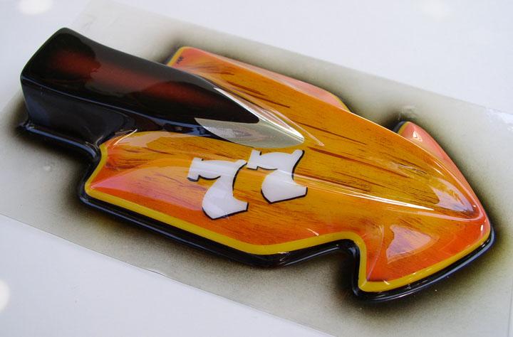
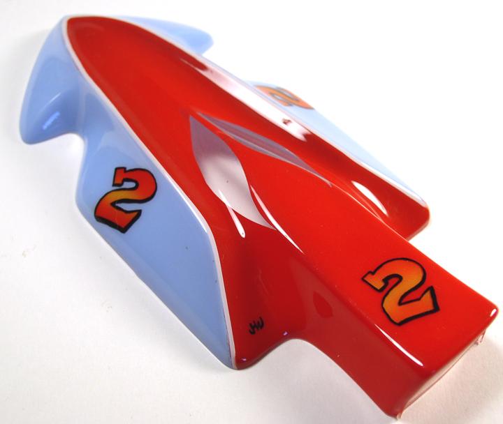
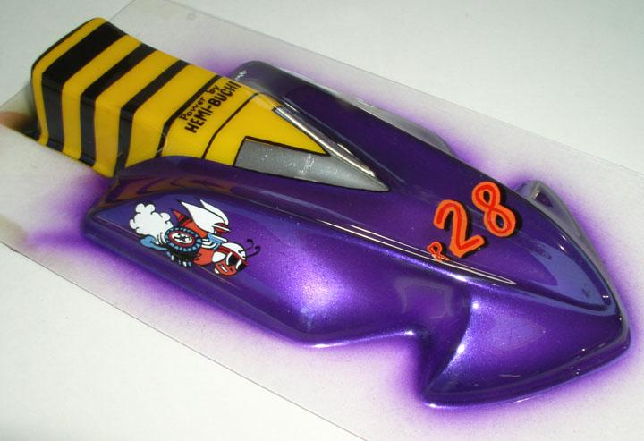
Several months ago a friend of mine sent me a reproduction of a classic Thingie body that I had not seen in a very long time. It was a "Hammerhead" (I presume like the shark), so I decided I had to build a chassis to fit!
For those who may not be familiar, this is what a Hammerhead Thingie body looks like:
I thought about this for awhile and decided to go with a design that would conform to standard (for 1968) construction techniques, but make full use of the body shape to try to enhance the handling characteristics.
The actual design could be called an "inline bat pan", but it occurred to me that the overall body shape bears a passing resemblance to modern "Ultimate Indy" bodies, so I could go with a similarly shaped chassis and get a fair amount of mass directly over the guide post by using a "winged" nose piece as in a more modern chassis design.
In addition, instead of using a drop arm, which would be correct for 1968, I would hinge and suspend a split front axle (granted, this is pretty radical for 1968, but this IS a "Thingie"...)
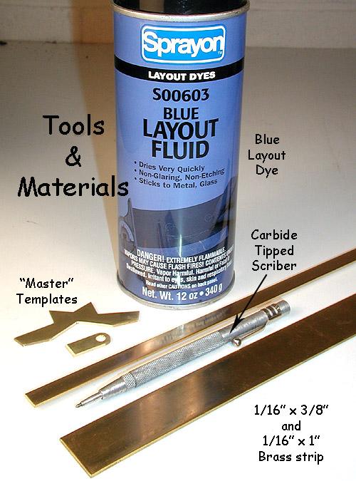
I started this build with the nose piece, so let's gather up the tools and materials:
The blue layout dye is available in spray can (as here), or in a small bottle with an applicator brush. In a pinch, you could use armature dye, but that would get expensive. The carbide tipped scriber is available at any well stocked hardware store. The brass is K&S. That 3/8" wide stuff is a bit unusual and not normally available in hobby shops, so I bought it from Special Shapes on the Internet.
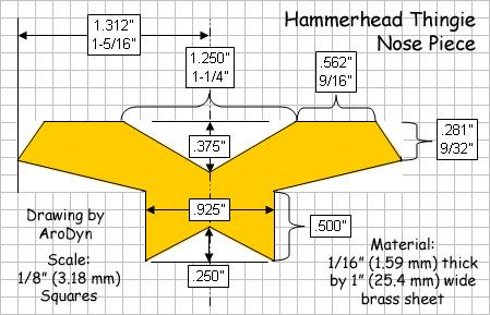
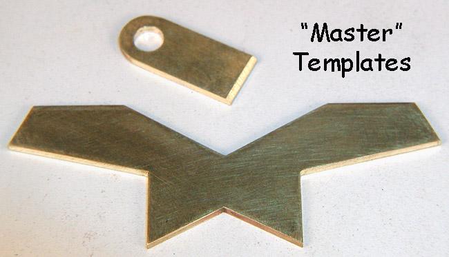
The "Master" template is a part I don't use to build the chassis; rather I use it to make duplicate parts, and I use those duplicate parts to build the chassis.
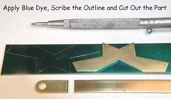
Apply some blue dye to the 1/16" thick (1.59 mm) by 1" (25.4 mm) wide brass strip, and lay the master template on top, with it's leading edges aligned with the edge of the brass strip. Scribe an outline in the dye with the scriber. If you want more nose pieces, just scribe some more lines. Now cut out the part and file the edges to the exact dimensions, keeping the edges straight and square. The guide tongue is cut out of a piece of 1/16" thick by 3/8" (9.53 mm) wide strip.
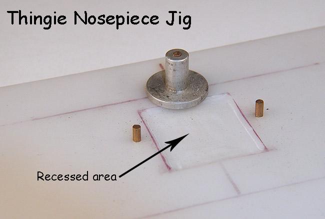
Here I've built a simple jig out of a scrap of Corian for the purpose of assembling the nose piece parts. The secret is the slight recess underneath the area of the nosepiece where the solder will go. It only needs to be about .030" (.76 mm) deep to work properly.
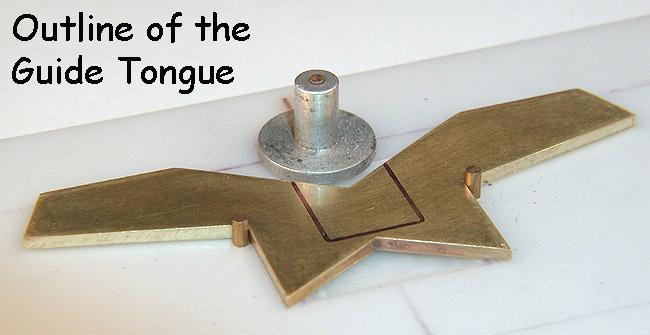
Lay in the parts and align the guide tongue. Now draw a line around the guide tongue with your handy-dandy Sanford Ultra-Fine Point Sharpie marker pen.
With the guide tongue removed, you can see the outline more clearly.
Now, tin the parts...
After cleaning everything up, apply a thin layer of paste flux to the tinned area and reassemble. Apply lots of heat using a "dry" iron (here I use a Hakko 455); we don't want any solder on top of the guide tongue!
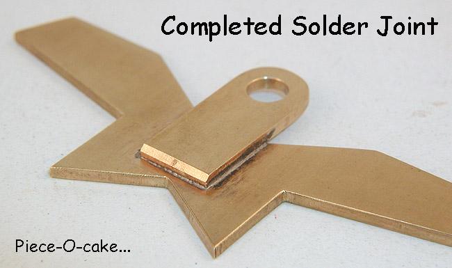
Completed solder joint requiring minimal cleanup.
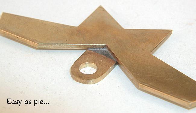
The nose piece is finished and ready to go.
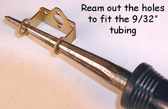
Next comes the motor bracket. I start by reaming out the 1/4" holes to fit a single piece of 9/32" bearing tube, instead of trying to piece together two 9/32" bearing tubes and two 1/4" alignment sleeves. I got this idea (stole it actually), from Rick Thigpen.
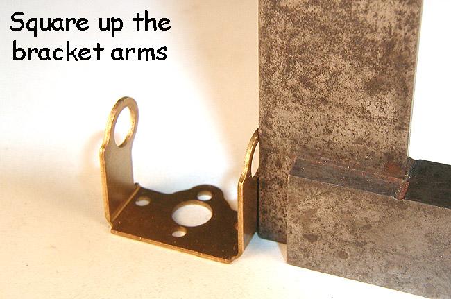
Now I do something that we should all be doing, every time! Don't ASSume manufactured parts are straight, square, flat or properly aligned; check it (and you will normally end up fixing it) before you build something with it!
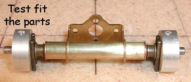
Cut a single piece of 9/32" brass tube that will eventually form the two bearing tubes. The length will be to suit your particular application. Here, the tube is 1-1/2" long. Assemble the parts to see that everything fits and is aligned properly.
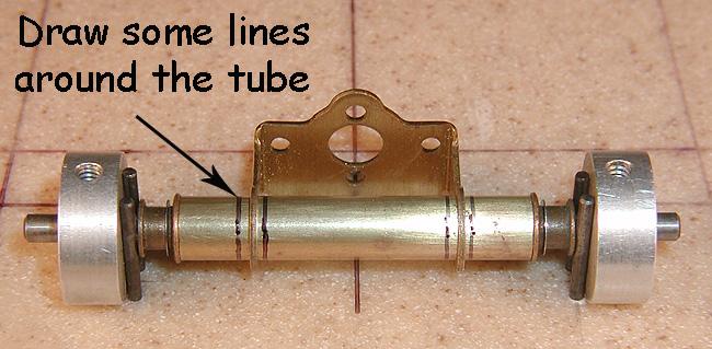
Now, grab that Sanford Ultra-Fine Point Sharpie marker pen and draw some lines around the tube. You can hold the pen steady and rotate the tube under it to get the straight lines.
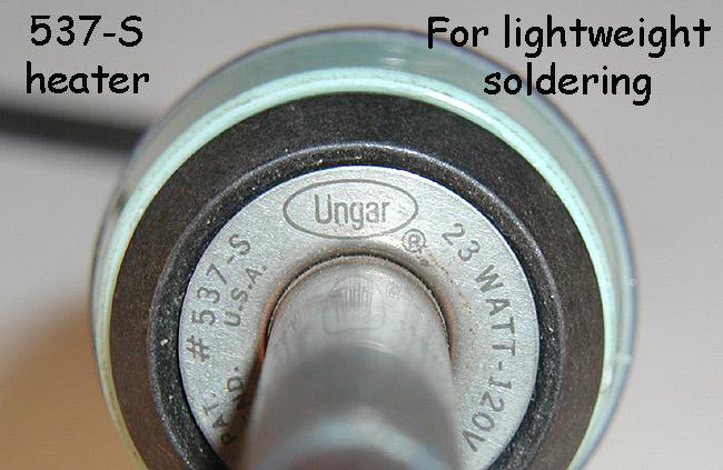
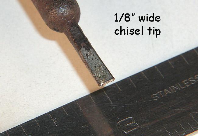
These will be small, low mass solder joints, so I will use a smaller iron with a smaller tip.
The tip is only 1/8" wide.
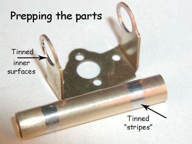
Apply a small amount of paste flux between the lines on the tube, and tin that area. Now, tin the inner surfaces of the bracket holes. Use minimal amounts of solder so the parts will still fit when you reassemble them.
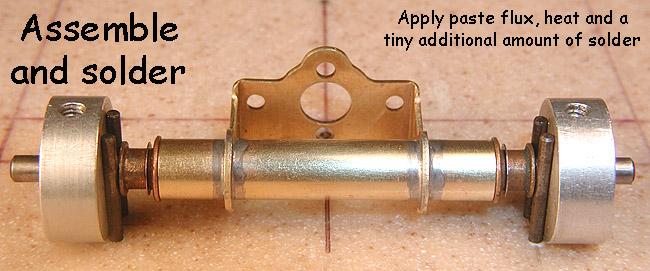
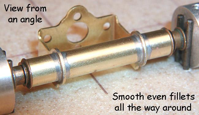
Again, after cleaning up the parts, put it all back together, apply a small amount of paste flux to the joint, and solder it up. Use a tiny amount of additional solder here to get a smooth, even fillet all the way around.
A view from an angle.
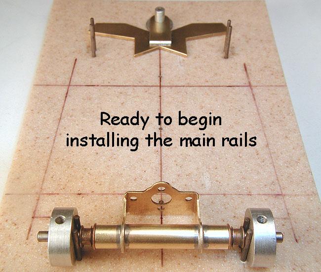
With the nose piece and motor bracket finished, now we are ready to begin installing the main rails.
Next up, building the center section... (Click here)


