

I’ve finally decided to post a build sequence for one of my chassis here… Seemed like a good time for it.
If you’re looking for a chassis tumbled to shiny beauty with perfect soldering, well, this ain’t it. You also won’t see any state-of-the-art scratchbuilding jigs or wire benders; we’re talking graph paper with lots of blue tape, and needle-nosed pliers. Okay, there is a “jig”, but see if you don’t laugh when you get to those photos…
Some may find the design and build to be overly complicated, long and tedious; but for me it is just the way I enjoy building them these days. And, no, I do not think this is a “better” way to build a chassis; it is merely where I wound up contemplating ideas and trying to make them functional out of a bunch of wire. Nor do I expect others to copy this or any of my builds; I am merely presenting my work for your perusal. My only hope would be that you find some value after looking through this, even if it is just mild enjoyment.
1229-Ca2
This chassis is my "1229" design; the "-C" suffix means it is a Retro inline chassis; the "a" designates the chassis has a 4.0" wheelbase, and a 5.0" rear axle to guide pivot length; the final "2" indicates the framing is made from 0.039" wire (so during the build sequence all wire is 0.039" unless noted otherwise).
1229-Ca2 Build Sequence, Part 1
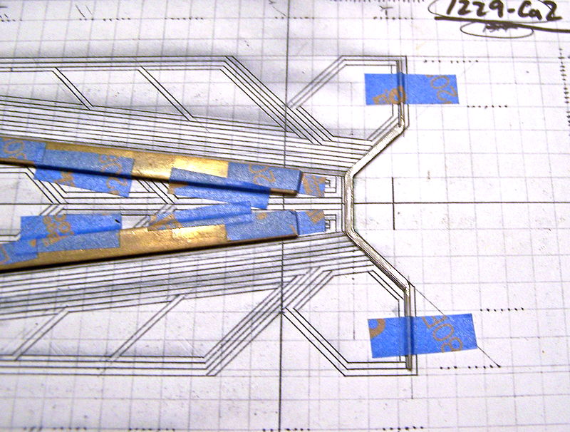
Picture 1: The four-bend front spanning wire is fashioned, assuring it is flat.

Pictures 2 & 3: The four-bend front spanning wire is taped in place; for stiffening, second two-bend wire is bent to fit against its three medial lengths; the wires are soldered together.

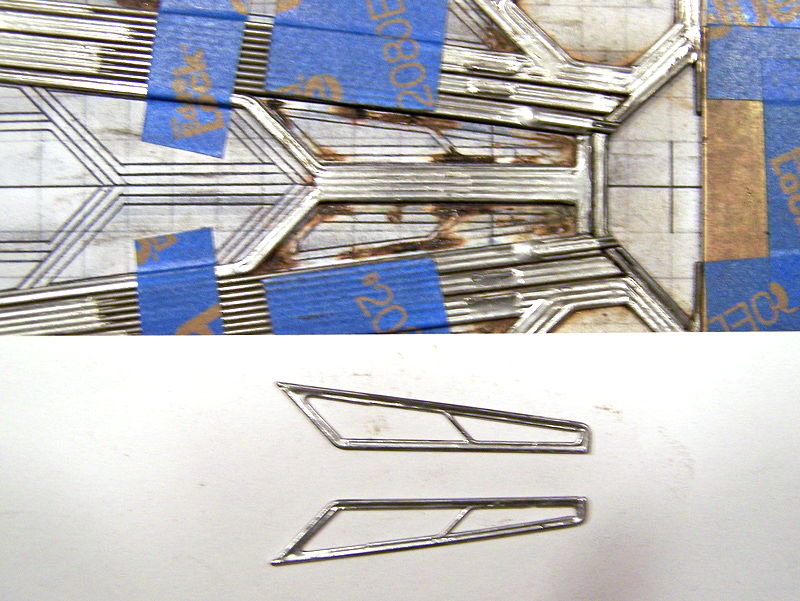
Picture 4: Front Axle Rails; each front axle rail consists of one one-bend wire (the rear length is longer than needed to allow for a rear axle tube upright bend later) flanked along its forward length on each side by two straight wires; they are soldered together at both ends (not entire length).

Pictures 5 - 11:
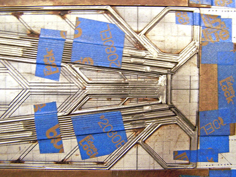
Indirect Main Rails (IMR); The indirect main rails (or "z-rails") for this build are a 2-1-2 set-up (2- wires project forward from the chassis rear assembly; -1- connecting wire in-between; -2 wires attach to the front chassis assembly). They also incorporate framed triangular areas at the rear-lateral aspect for the addition of pans later.
Picture 5: The first IMR one-bend wire is shaped to lie lateral to the front axle rail assembly (the rear length is longer than needed to allow for a rear axle tube upright bend later).
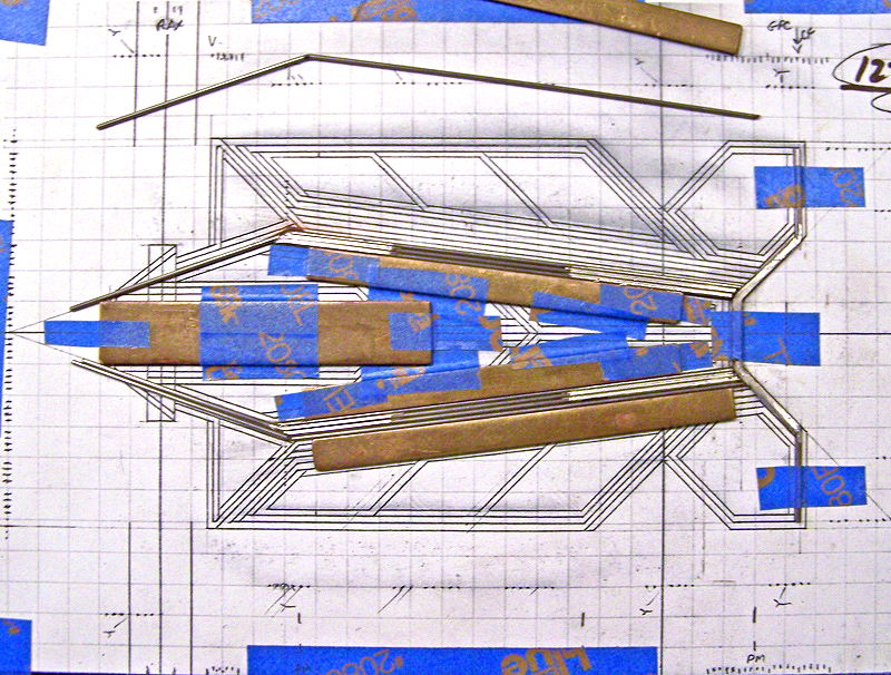
Picture 6: The second IMR two-bend wire is shaped to lie adjacent to the forward length of the first; the bends outline the triangular pan area; the two wires are soldered together front and rear (see Picture 7).

Picture 7: A one-bend wire is soldered to the rear of the first two IMR wires to close the triangular pan area.

Picture 8: Another one-bend wire is soldered inside the forward angle of the triangular pan area.
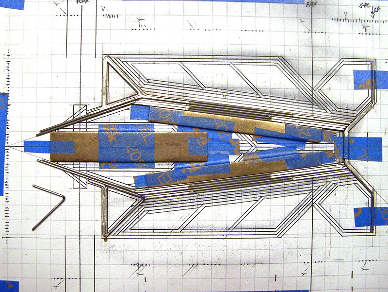
Picture 9: The single straight IMR connecting rail is soldered to the forward portion of the first two wires.

Picture 10: The first of two one-bend wires that will attach to the chassis front assembly is soldered to the rear of the IMR connecting wire (but is not soldered to the front spanning wire at this time).


CMF3 1229-Ca2 Retro chassis build sequence
#1

-
- Full Member
-

- 500 posts Joined: 22-November 09
CMF3
- Gender:Male
- Location:Tampa
Posted 19 November 2013 - 09:50 AM
#2
-
- Full Member
-
- 500 posts Joined: 22-November 09
CMF3
- Gender:Male
- Location:Tampa
Posted 19 November 2013 - 09:55 AM
1229-Ca2 Build Sequence, Part 2
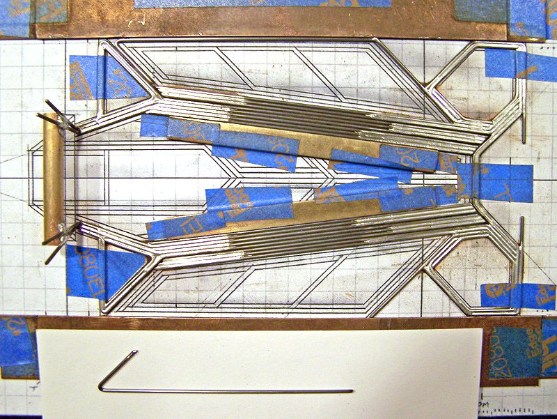
Picture 11: The second of the two one-bend wires that will attach to the chassis front assembly is soldered to the rear and front portions of the adjacent wire (and, also is not soldered to the front spanning wire at this time).

Picture 12: Stop laughing; yes that is an older-than-dirt Champion Align-O-Jig. For cryin out loud, Im using needle-nosed pliers to do the wire bending, and my jig is graph paper and blue-tape High-tech just aint my style.
The 7/32 D x 1.40 L rear axle tube is jigged into place.

Picture 13: The rear axle tube upright bends are made on the IMR assemblies.

Picture 14: The floating front wires (3x, medial) of the IMR assembly that do not attach to the front spanning wire are trimmed to ensure clearance; the IMR assembly is then soldered to the rear axle tube and front spanning wire.

Picture 15: The rear axle tube upright bends are made on the front axle rail assemblies.

Picture 16: The forward ends of the front axle rails (that do not attach to the front spanning wire) are trimmed to ensure clearance, and then they're soldered in place to the rear axle tube and rear portion of the adjacent wire of the IMRs.

Picture 17: Heres what it looks like so far with the jig removed.

Pictures 18 22:
Front Wing Assemblies; consist of five wires each.
Picture 18: The first front wing assembly wire is a one-bend wire soldered to the lateral-most IMR wire; this outlines the rear of the front wheel well.

Picture 19: The second front wing assembly wire is a two-bend wire soldered to the first wire and forward surface of the front spanning wire; this outlines the front of the front wheel well. (I keep these longer than needed along the front of the chassis for alignment purposes; they are trimmed off at chassis completion.)

Picture 20: A two-bend wire is soldered to the first two wing assembly wires.

#3
-
- Full Member
-
- 500 posts Joined: 22-November 09
CMF3
- Gender:Male
- Location:Tampa
Posted 19 November 2013 - 10:01 AM
1229-Ca2 Build Sequence, Part 3
Picture 21: A one-bend wire is soldered in to reinforce the first and third wing assembly wires.

Picture 22: The final one-bend wing assembly wire is soldered in to reinforce the second front wing assembly wire, the front spanning wire and the attachment point of the IMRs.

Pictures 23 26:
Perimeter-Wire Outer Side Pans; these consist of four wires each, two lateral and two medial.
Picture 23: The first one-bend lateral-most outer side pan wire is tack-soldered to the end of the rearward front wheel well wing assembly wire.
Picture 24: The second one-bend lateral outer side pan wire is soldered inside of the first wire and the rearward front wheel well wing assembly wire.

Picture 25: The third one-bend medial-most outer side pan wire is soldered to the rear length of the first wire and the forward length of the adjacent IMR wire.

Picture 26: The fourth (final) straight medial outer side pan wire is soldered to the rear and front lateral sides of the third wire.

Picture 27: This is how the chassis appears so far.

Pictures 28 31:
Inner Side Pans; these consist of two 0.032" wires and five 0.024" wires each; they are optionally fabricated at this time, but are NOT attached to the chassis.
Picture 28: The two one-bend 0.032" wires that define the perimeter of the inner side pans are fashioned to fit within the perimeter wire outer side pans; note: these should be made to allow a tiny gap between them and the outer pan wires; they are tack soldered together at their forward and rearward points.

Picture 29: Two two-bend 0.024 wires that supply cross-support are tack soldered into place. (One of these inner pans is shown within the outer side pan to show the relative position of these cross-support wires.)

Picture 30: The final three 0.024" inner support wires, two one-bend wires and one straight wire, are tack-soldered into place.

#4
-
- Full Member
-
- 500 posts Joined: 22-November 09
CMF3
- Gender:Male
- Location:Tampa
Posted 19 November 2013 - 10:07 AM
1229-Ca2 Build Sequence, Part 4
Picture 31: The 0.032" wires and 0.024" wires are soldered together around the entire outer perimeter of the inner side pans. Place the two inner side pans aside; they will not be installed until Picture 86.

Picture 32: (Blur!) The front axle rail down-stops are installed. Two pieces of 0.032" wire are soldered side-by-side for a distance shorter than the distance from the front spanning wire to the center-line of the front axle (this is where the spanning up-stop wire for the center-guide section / IMRs will run later). Carefully these are soldered atop the foremost portion of the front-axle rails (only!), ensuring they rest atop but no solder gets onto the front spanning wire (or adjacent IMRs).
Note 1: It is easier to make these longer than needed, and to cut the forward excess length off after installing (see Picture 33).
Note 2: The forward front-axle upright will be placed atop these down-stops at a later step.

Picture 33: A wire is soldered atop each of the forward edge of the two angled portions of the front spanning wire. These wires act as lateral movement restrictors for the guide and the front axle rail down stops.

Picture 34: Four small 0.024" bump-wires are soldered to the forward floating portion of the IMRs (one each) and to the adjacent connecting IMR rail / perimeter pan wire (one each), along the front axle line. These bump-wires will abut against the underside of the spanning up-stop wire for the center-guide section / IMRs (see Picture 51); the bump-wires are added as spacing to the connecting IMR / perimeter pan wires where the spanning up-stop wire will soldered in place to keep it at the same level as the bump-wires. (Note: No bump-wires are attached to the front-axle rails.)

Pictures 35 50:
Center-Guide Section:
Pictures 35 39: Center-Guide section main framing
Pictures 40 45: Center-Guide section flanking pans
Pictures 46 47: Guide tongue installation
Pictures 48 49: Center-Guide section installation
Picture 50: Center-Guide section bump-wires
Picture 35: The center-guide section is started with two straight wires tack-soldered together perpendicular to each other; the first short wire is parallel and just behind the center length of the front spanning wire and is 0.047" wire (0.047" wire is used to give the guide tongue a slight upward tilt later); the second wire runs rearward from the first along the chassis center-line, and is longer than needed to ease installation (and is trimmed to size later). No portion of the center-guide section is attached to any other part of the chassis framing until later (Picture 49).

Picture 36: (Blur!) Two one-bend wires are soldered to the first two wires (only shown tack-soldered in the picture) to complete their connection. Note: The length of these wires parallel to the center-line wire is only about 0.75", and not the entire length of the structure.

Picture 37: (More blur!) Two pieces of straight wire are placed along the sides of the remaining length of the center-line wire for spacing purposes only. A two-bend wire is soldered (only) to each L-shaped wire.

Picture 38: (Still blurry!) The two spacing wires are removed.

Picture 39: A three-bend wire is shaped to fit from each of the spaces along the rear of the center-line wire, paralleling the two-bend wire from Picture 37, and beyond the rear axle tube; the excess length is used to make a rear axle tube upright later (Picture 48). It is soldered to the center-line wire and the two-bend wire from Picture 37 only.

Picture 40:
The excess length of the center-line wire is removed.
The center-guide section flanking pans consist of two 0.032" wires and five 0.024" wires each.
The two one-bend 0.032" wires that define the perimeter of the center-guide flanking pans are fashioned to fit within the space between the center-guide section framing and the front axle rails; note: these should be made to allow a tiny gap between them and the surrounding wires; they are tack soldered together at their forward and rearward points.

#5
-
- Full Member
-
- 500 posts Joined: 22-November 09
CMF3
- Gender:Male
- Location:Tampa
Posted 19 November 2013 - 10:13 AM
1229-Ca2 Build Sequence, Part 5
Picture 41: A two-bend 0.024" wire that supplies cross-support is tack-soldered into place.

Picture 42: The final four 0.024" inner support wires, two one-bend wires and two straight wires, are tack soldered into place.

Picture 43: (Getting some blur again) The 0.032" wires and 0.024" wires are soldered together around the entire outer perimeter of the center-guide flanking pans.
Picture 44: The center-guide flanking pans are soldered in place, attaching only to the front of the center-guide section framing to about 0.625" rearward.
Picture 45: (Yeah, more blur) The one-bend 0.032" down-stop wire is soldered to rear of each center-guide flanking pan; making sure it rests atop but no solder gets on the center-guide section framing. Again, it is easier to make these longer than needed, and to cut the forward excess length off after installing.

Picture 46: A piece of 0.025" brass plate is tinned and soldered atop the front (approx. 0.375") of the center-guide section. It is easier to make this piece larger than needed and trim it to fit.

Picture 47: The guide tongue (Slick 7 S7-25) has been narrowed to ensure it will not contact the front-axle rails, tinned, and then soldered in place.

Picture 48: The rear axle tube upright bends are made on the center-guide section.

Picture 49: The center-guide section is soldered into place, attaching to the rear portion of the adjacent front axle rail wires and the rear axle tube.

Picture 50: Two small 0.024" bump-wires are soldered atop the framing of the center-guide section (along the front axle line). These also function along with previous bump-wires (Picture 34) under the spanning up-stop wire (see Picture 51).

#6
-
- Full Member
-
- 500 posts Joined: 22-November 09
CMF3
- Gender:Male
- Location:Tampa
Posted 19 November 2013 - 10:20 AM
1229-Ca2 Build Sequence, Part 6
Picture 51: The two-bend spanning up-stop wire for the center-guide section and IMRs is soldered in place; it is placed along the line of the front axle, which will be suspended above it, and rests atop the bump-wires.

Pictures 52 57:
Motor Box Extension framing
Picture 52: The motor box extension is started with two wires tack-soldered together. The first is a 1onebend wire just behind rear of the center-guide section, and is made to allow a tiny gap between itself and the adjacent center-guide section wires. The second is a straight wire running from the angle of the first rearward along the chassis center-line; and again longer than needed to ease installation (and is trimmed to size later).

Pictures 53 & 54: A one-bend wire is soldered to each lateral length of the first wire; it too should fit with a tiny gap between itself and the forward portion of the adjacent center-guide section wires. Picture 54 shows its rear length soldered to the adjacent center-guide section wires.
 ]
]

Picture 55: A two-bend wire is soldered to each side of the center-line wire and to each wire from Pictures 53 / 54.

Picture 56: A one-bend wire is soldered to each of the two forward lengths of the wires from Picture 55.

Picture 57: A one-bend wire is soldered to each of the two forward lengths of the wires from Pictures 53 / 54.

#7
-
- Full Member
-
- 500 posts Joined: 22-November 09
CMF3
- Gender:Male
- Location:Tampa
Posted 19 November 2013 - 10:28 AM
1229-Ca2 Build Sequence, Part 7
Pictures 58-62:
Motor Box framing
Pictures 58 - 60:
The excess length of the center-line wire is removed.
The one-bend (with rear axle tube upright bend) inner motor box wires are soldered to the rear axle tube and to the rear of the motor box extension wires.
Note 1: This motor box is sized for FK-type motors; as a matter of spacing, I use a 0.5" wide piece of 0.064" brass flanked on each side by a length of 0.047" wire, for approximately 0.6" spacing.
Note 2: Where the IMRs, front axle rails and center-guide section rear axle tube uprights attached to the front of the rear axle tube, the motor box rear axle tube uprights attach to the rear of the rear axle tube.


Picture 61 & 62: The straight (with rear axle tube upright bend) outer motor box wires are soldered to the rear axle tube and inner motor box wires.
The excess lengths of all the wires connecting to the rear axle tube are removed.

Picture 63: The four-bend (two-plane) gear-guard wire is shaped and soldered to the rear portion of the inner motor box wires (behind where the motor bracket face will be placed; see Pictures 68 & 69 for reference).

Picture 64: The two-bend rear axle tube spreader wire is soldered atop of the gear-guard and to the ends of the rear axle tube.

Picture 65: The center portion of the rear axle tube is removed. (Also, another view of the gear guard / spreader.)

Picture 66: A short wire is soldered atop each side of the motor box; this helps to cradle the motor and affords easier points to solder the motor in place.

#8
-
- Full Member
-
- 500 posts Joined: 22-November 09
CMF3
- Gender:Male
- Location:Tampa
Posted 19 November 2013 - 10:35 AM
1229-Ca2 Build Sequence, Part 8
Picture 67: The motor bracket (JK-D3F122) is modified.

Picture 68: The modified motor bracket is positioned so the motor will be angled such that the shaft of the motor will be perpendicular with the rear axle while keeping the front of the motor flush with the bottom plane of the chassis, and soldered into place; this allows for a better gear mesh than with an offset, or hypoid, motor mounting gear mesh, while keeping the mass of the motor as low as possible.

Picture 69: Four pieces of 0.010" brass sheet are cut to fit the two triangular sections of the IMR wires and the two quadrangular sections of the motor box extension, and soldered in place.

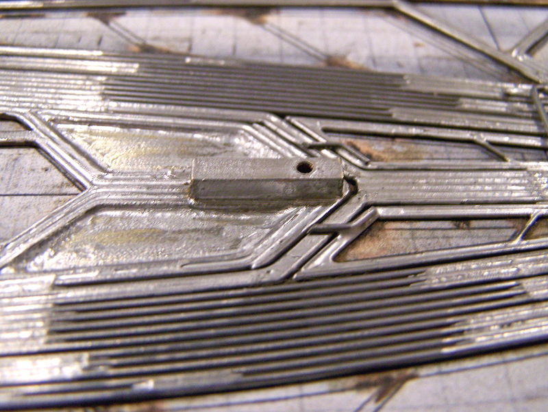
Picture 70: The control box for the variable spring-wire tension (VSWT) system for the front axle rails is soldered atop the center-forward wires of the motor box extension; the control box is a 1/8 square brass tube cut 5/8" long with a 1/16" hole drilled in one side 5/32" from the front of the tube. (A FK-type motor mounting screw will be tapped into the drilled hole and used as the adjuster for the VSWT.)
Picture 71: A two-bend 0.047" bracing wire is soldered to each side of VSWT control box, atop the motor box extension and to the back of the chassis; this wire helps to stiffen the motor box extension, counteracting the forces exerted on it by the VSWT spring wire.

Picture 72: This picture just shows the progress to this point in the build.

Picture 73: A 0.024" spring wire is soldered to the center-guide section so that it rests atop the spanning wire up-stop. Note: This spring wire is set to zero-tension when in its static or at-rest position.

Picture 74: A 0.024" spring wire is soldered to each forward floating section of the IMRs so that it rests atop the spanning wire up-stop. Note: These spring wires are set to zero-tension when in their static or at-rest position.

#9
-
- Full Member
-
- 500 posts Joined: 22-November 09
CMF3
- Gender:Male
- Location:Tampa
Posted 19 November 2013 - 10:41 AM
1229-Ca2 Build Sequence, Part 9
Picture 75: The outer perimeter side pan movement restrictor box is soldered to the main framing just forward of the triangular brass pans; the restrictor box is 1/8" square brass cut to 0.35" length.

Picture 76: A two-bend piece of 0.055" wire is soldered to each of the outer perimeter side pans so they extend into the movement restrictor box; they should just make contact with the inner side of the square brass tube. This completes the outer perimeter side pan movement restrictors.

Picture 77: A small two-bend 0.032" down-stop wire is soldered to the rear floating end of each IMR, so that it rests atop the outer perimeter side pan restrictor box.

Pictures 78 81:
Front Axle Spanning Uprights: The spanning uprights add lateral strength to the chassis; they are also angled away from perpendiculars for greater strength; the spanning uprights also make axle setting/changing easy.
Picture 78: The two four-bend (two-plane) front axle (FAX) uprights are shaped; the rear FAX upright is on the left, the front FAX upright is on the right.

Picture 79: The front FAX upright is soldered atop the front axle rail down-stops.

Picture 80: The rear FAX upright is soldered atop the front axle rails.

Picture 81: This shows a side view of the FAX uprights in place.

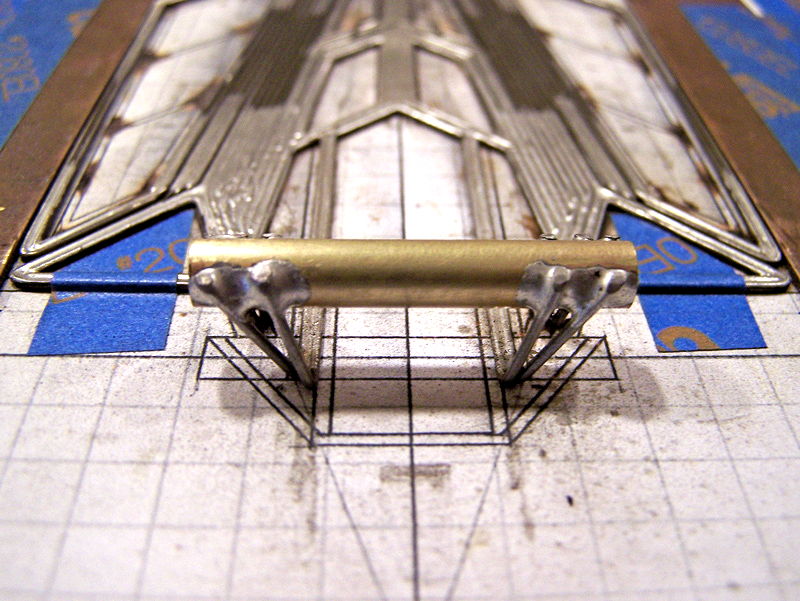
Picture 82: A two-bend wire is soldered atop the base of the rear FAX upright. Note: This spanning wire should not contact the center-guide section spring wire below it. (This wire is to allow contact points for the VSWT spring wire; see Picture 83.)

Picture 83: Two small (0.125") pieces of 3/32" square brass tubing are soldered to each side of the rear FAX upright base spanning wire. These are the forward contact points for the VSWT spring wire.

#10
-
- Full Member
-
- 500 posts Joined: 22-November 09
CMF3
- Gender:Male
- Location:Tampa
Posted 19 November 2013 - 10:46 AM
1229-Ca2 Build Sequence, Part 10
Picture 84: The rear spring-mounted body pin tubes consist of a piece of 1/16" brass round tube, a 1/16" brass collar, and a two-bend 0.024" wire shaped to fit over the outer perimeter side pan where the pin tube will be located.

Picture 85: The ends of 0.024" wire of the assembled rear spring-mounted body pin tubes are soldered to the outer perimeter side pan wires approximately 1.125" forward of the pin tube. The inner end of the 1/16" brass pin tube should just rest against the side pan restrictor box.

Picture 86: The completed inner side pans (from Pictures 28-31) are now soldered to the forward V defined by the outer perimeter wire pan. Remember, there should be a tiny gap between the inner side pans and the outer perimeter wire pans.

Picture 87: (Blurs back) The middle body mount pin tubes (1/16" brass tube with 1/16" brass collars) are soldered into place just behind the front wheel wells.

Picture 88: A small two-bend 0.032" down-stop is soldered to the inner rear floating end of each inner side pan, so that it rests atop the outer perimeter side pan restrictor box (and just rearward of the rear IMR down-stops).

Picture 89: A 0.024" spring wire is attached to the chassis main frame so that it rests atop the inner side pan and rear IMR down-stops.

Picture 90: The front body mount pin tubes (1/16" brass tube with 1/16" brass collars) are soldered into place forward of the front wheel wells.

Picture 91: The five-bend 0.032" VSWT spring wire is formed, soldered, and inserted into the VSWT control box and brass tubes atop the rear FAX upright base spanning wire. An FK-type motor mounting screw is tapped into the VSWT control box.

#11
-
- Full Member
-
- 500 posts Joined: 22-November 09
CMF3
- Gender:Male
- Location:Tampa
Posted 19 November 2013 - 10:49 AM
The completed chassis!

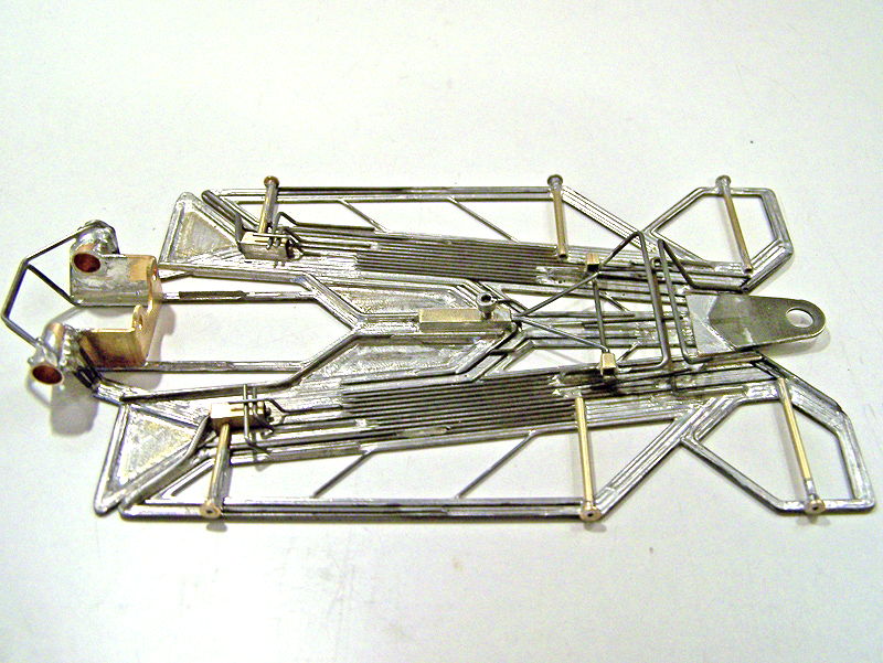


See, nothing to it...
- endbelldrive likes this
#12
-

- Subscriber
-
- 994 posts Joined: 15-January 07
Troublesome De-slotter
- Gender:Male
- Location:Lost in South Carolina, USA
Posted 19 November 2013 - 12:35 PM
Absolutely beautiful craftsmanship! It's obvious that you have much more patience than I do.
Thanks for sharing.
South Carolina, USA
"Assuming either the Left Wing or the Right Wing gained control of the country, it would probably fly around in circles."
- Pat Paulsen, 1968
"I drive way too fast to worry about cholesterol."
- Steven Wright ca. 1983
#13
-

- Full Member
-
- 473 posts Joined: 31-May 10
On The Lead Lap
- Gender:Male
- Location:Cranston, RI
Posted 19 November 2013 - 12:46 PM
... for lack of a better way to put this, my mind is blown. I'm fairly new to building Retro chassis and I've yet to even imagine a build like this. Thank you for the detailed posting showing the progression of the build.
I only have one question. With all other slot cars I've raced, it was important to have the guide tongue bent at a very slight upward angle thanks to the rake created by the rear chassis clearance. Do you need the same sort of thing on a retro chassis? Unless I missed something, I'm guessing the tongue is just soldered flat on top of the brass spacer with no angle added
obSCEne Chassis
HVR BB Fronts
Bodies by Weaver
"There is no such thing as a race you are destined to lose. You will always have a chance."
#14
-

- Full Member
-
- 1,173 posts Joined: 15-April 11
Checkered Flag in Hand
- Gender:Male
- Location:CT
Posted 19 November 2013 - 01:11 PM
I only have one question. With all other slot cars I've raced, it was important to have the guide tongue bent at a very slight upward angle thanks to the rake created by the rear chassis clearance. Do you need the same sort of thing on a retro chassis? Unless I missed something, I'm guessing the tongue is just soldered flat on top of the brass spacer with no angle added
Picture #35 - the .047" wire provides the upward angle (This is my guess).
I've followed these builds for a while after Marty Stanley recommended them.
#15
-

- Root Admin
-
- 25,547 posts Joined: 14-February 06
Headmaster of the asylum
- Gender:Male
- Location:Norcross, GA
Posted 19 November 2013 - 01:22 PM
What I like about his thread is that it shows a unique method of chassis construction that is all Rick's, like the telltale style of a great artist. Plus he showcases the depths of the thought and design processes he uses, as well as the complete details of the construction process. The term "tour de force" comes to mind.
Bravo, Rick!
- MSwiss likes this
Gregory Wells
Never forget that first place goes to the racer with the MOST laps, not the racer with the FASTEST lap
#16
-

- Banned
-
- 5,278 posts Joined: 05-March 06
Grand Champion Poster
- Gender:Male
- Location:Wellington, New Zealand
Posted 19 November 2013 - 02:11 PM
What is it going to handle like?
Will it be best on a flat track or one with banking?
I am finally going to get the chance to drive one of your chassis tomorrow evening in the New Zealand leg of the "Lucky 13" International Thingies Proxy Series. 
#17
-
- Root Admin
-
- 25,547 posts Joined: 14-February 06
Headmaster of the asylum
- Gender:Male
- Location:Norcross, GA
Posted 19 November 2013 - 02:23 PM
Zip, I've seen Rick's chassis run and I think you should have no worries at all about how they handle.
Gregory Wells
Never forget that first place goes to the racer with the MOST laps, not the racer with the FASTEST lap
#18
-

- Full Member
-
- 14,317 posts Joined: 02-August 07
Age scrubs away speed!
- Gender:Male
- Location:New Boston, NH
Posted 20 November 2013 - 03:48 PM
Rick, one very detailed build article. Nice job! I've got the graph paper & the Champion Align-O-Jig plates. I'll have to see what sort of a design I can come up with, then buy some .039 wire to see if I can build it. 
I intend to live forever! So far, so good.
#19
-
- Full Member
-
- 1,173 posts Joined: 15-April 11
Checkered Flag in Hand
- Gender:Male
- Location:CT
Posted 20 November 2013 - 10:31 PM
Zip, I've seen Rick's chassis run and I think you should have no worries at all about how they handle.
I've only seen the race reports. I can see how well they run. What I want to know is how they work.
Great article on how to build this. It showed many of the things I have had trouble visualizing.
#20
-
- Full Member
-
- 500 posts Joined: 22-November 09
CMF3
- Gender:Male
- Location:Tampa
Posted 21 November 2013 - 02:22 AM
Thanks for the kind words, gentlemen.
Yes, Bob is correct. The 0.047” wire at the front of the center-guide section in Picture 35, being slightly higher than the 0.039” framing wire, gives the slight upward tilt to the guide tongue. I used to grind, file and sand the framing, until one day it finally dawned on me all I had to do was use the next size larger wire at the front… I felt like a complete idiot for not having realized something so simple for so long. Oh well.
I’m also aware that some might question the strength of the guide tongue mounting in this manner. But I’ve been doing it this way now for about 18 years, and have yet to have one break. I’m not saying that it can’t happen, just that it hasn’t.
As to “how” it works, well, that’s a long story, and still a work in progress. The 1229 design is just the latest in a series of designs that progressed along from the idea of isolating the forces working on various parts of the chassis while minimizing the mass of any moving part. The center-guide section (which went through various incarnations) isolated the forces on the guide from forces on the front and sides of the chassis, and vice versa. The indirect main rails further isolated the front and sides from the motor box and rear axle assembly. The incorporation of inner and outer side “pans”, attached to the chassis front only (not to the main rails), decreased the amount of lateral moving mass on the chassis; the larger inner side pans are spring loaded and generally stay in the plane of the chassis; the “outer side pans” are really only wires around the perimeter of the inner pans, decreasing the mass of the structure, and are not spring loaded to allow for the usual free movement. Also, the spring-wire mounted rear body pin tubes further isolate body movement from the outer perimeter wire side “pans” that they are attached to. The front axle rails isolate forces working on the front wheels from the rest of the chassis, and quite by accident was found to be tunable by adjusting the tension on the front axle rail spring wire (hence the VSWT control box and adjusting screw).
The 1229 design took all this from previous designs and added the static lateral-rear triangular pans, and added the motor box extension assembly, which removed the VSWT control box from the center-guide section where it had been on previous designs, and which allowed for two more static pans at mid chassis just forward of the motor box.
The addition of the static pans, along with the general chassis structure of the 1229 design, allows me to now build these chassis in any dimensional layout using 0.039” wire for the framing and still be able to ensure the RTR cars will meet the (…sound of grinding teeth…) minimum weight requirements. Prior to the 1229’s, I only had one dimensional version of one chassis design (the 1225-Ca2) that would accommodate this regulation, so everything else was built using the 0.047” wire I’d been using since… well… since long before retro. (I also built a 0.032” wire framed 1225-Ca3, but that’s another story…) So, for 0.039” frames, I already had the 1229-Cb2, finished the 1229-Ca2 posted here, and I just started the side-by-side builds of the 1229-Cc2 and 1229-Cd2… Then I’ll get out and do some fooling around… uh… I mean, testing and comparisons of these…
Hey, Bill, sounds like you got everything you need. The way I figure it, all that money I save not buying “scratchbuilding equipment” gives me more money to spend on bulk orders of music wire I seem to go through faster than I can blink…

#21
-
- Root Admin
-
- 25,547 posts Joined: 14-February 06
Headmaster of the asylum
- Gender:Male
- Location:Norcross, GA
Posted 05 December 2013 - 11:08 AM
Gregory Wells
Never forget that first place goes to the racer with the MOST laps, not the racer with the FASTEST lap


