Jump to content


Photo

Pablo IRRA® Stock Car step-by-step


  • Please log in to reply
99 replies to this topic

#1 Pablo

Pablo

    Builder

  • Administrator
  • PipPipPipPipPipPipPipPip
  • 18,364 posts
  • Joined: 20-February 06
  • Gender:Male
  • Location:Cleveland, Tennessee

Posted 28 March 2014 - 09:30 AM

Finished April 2014:

post-91-0-32766000-1397670336.jpg


post-91-0-83561800-1397670348.jpg


Here's where it all started:

I liked the Mike Katz inspired stock car chassis design so much, I decided to make another one just like it.  This time I took a smart pill with a Coke on ice, gathered up the Weller Gun, 60/40, acid, fan, table, clamp light, latex glove, 400 wet/dry sandpaper, the pieces of piano wire, long extension cord, and set up a serious wire tinning camp in the back patio with the fan sucking the acid fumes away. I thought the latex glove would instantly fail once it touched acid, but it didn't.  I should have been doing it this way a long time ago.....I tinned half of each piece then set it down to cool, picked up the next one, and so on until I had a nice pile of tinned wires. Hint: A Weller Gun Model 8200N is the bomb-diggety for tinning wire, especially if you take a small round file and carve a small U-shaped groove on the front bottom of the tip for the wires to nest in. Use lots of flux and lots of solder until it flows nice and wet, then wipe wipe wipe 3 times real fast with a paper towel. You need:
-a piece of 3/32 front axle a little longer than the width of the jig (Note: tin only the inside middle 2" of this piece - if you tin the entire length the wheels may not slide on the axle)
-2 pieces of .078 longer than needed for rails to run from back of bracket to the front end
-2  4" pieces of .063
-6  4" pieces of .055
-1  4" piece of .047
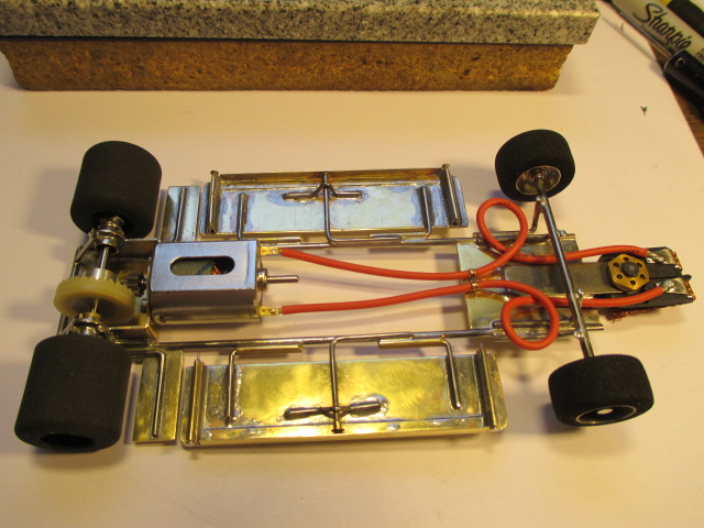
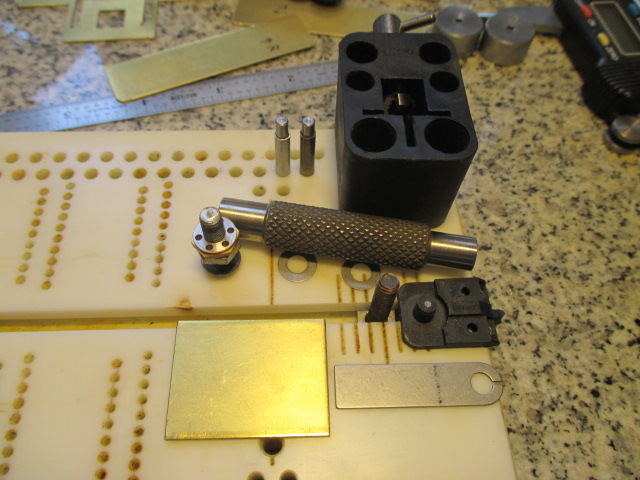
Parts needed for the build are a JK D3 offset motor bracket, Chicagoland .032 thick Brackagra bracket brace/weight, a chunk of 1.3" long by 1" wide .063 brass strip, a Slick 7 retro .050 steel tongue, 4 Avid RC $1.00 3/32 ball bearings, a pair of Pro Slot 3/32 ball bearings, 1 Koford rear axle no flats, HVR BB stock car front wheels, your choice of 3/32 13/16 rear wheels, four 3/32 front axle wheel keepers, some 7/32, .063, and 3/32 tubing, some 3/32 square tubing, some 1/8" "L" angle brass, .032 X 3/4" wide brass strips, an FK jig motor, 9 tooth ARP angled steel pinion, 28 tooth 48 pitch sleeved Parma or Red Fox or Koford crown gear, JK Hawk Retro motor, Slick 7 3/32 .023" axle spacers, RGeo rear retro jig wheels, Parma (The Blade) flag, two steel 10 thou flag spacers, Koford flag nut, TQ flag clips, Prime braid, an earring clutch back, some lead wires, and the IRRA legal stock car body of your choice with interior/driver and three numbers.
I'm going to go step by step with precise measurements so you can build your own Mike Katz inspired Pablo IRRA stock car. Hopefully you can avoid stupid mistakes which I have already made, such as, but not limited to, using "Front" retro jig wheels for the front axle of a stocker,  :dash2: or my personal favorite head banger "One hell of a big screwup" mistake of realizing the Brackagra needs to be trimmed to clear the inside edges of the rear wheels AFTER the chassis is 100% complete.  :dash2: You DO NOT want to spend an hour masking a chassis in tape then having the hungry teeth of your band saw a millimeter away from your ball bearings !!! NOT GOOD Pablo, not good !!!  :shok:
 
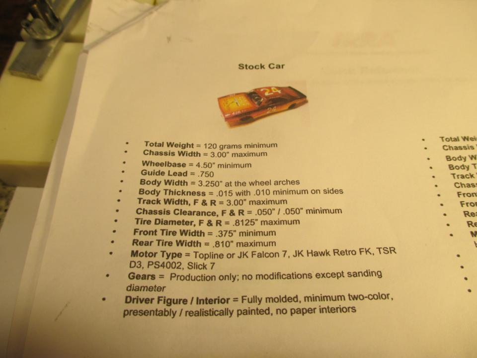
This is a real straightforward design using proven methods and parts that will make a nice handling car on a variety of tracks.  Your race weight will be 122 grams without additional weight. My instructions are aimed at the (rare) proverbial IRRA newbie. If you are an experienced builder you probably don't want to be force fed a bunch of Pablo theory BS and building tips.  If you want just the hard cold facts and specs just send me a PM and ask for my 1 page file "IRRA stock car Katz design". I welcome all experienced scratchbuilders to help me improve.  I do make mistakes but my Slotblog friends always correct me.  :D


  • Peter Horvath and John C Martin like this

Paul Wolcott


#2 SlotStox#53

SlotStox#53

    Posting Leader

  • Full Member
  • PipPipPipPipPipPipPip
  • 4,084 posts
  • Joined: 13-March 13
  • Gender:Male
  • Location:TX

Posted 28 March 2014 - 11:31 AM

Ooo a Pablo step by step build.... Nice :good: :D

What size front jig wheels do you need for the stocker Pablo? Haven't looked at the stock car rules yet, different size wheels I take it?

I would of ASSumed being "retro" stockers they'd require same jig & running wheels :laugh2:

#3 Pablo

Pablo

    Builder

  • Administrator
  • PipPipPipPipPipPipPipPip
  • 18,364 posts
  • Joined: 20-February 06
  • Gender:Male
  • Location:Cleveland, Tennessee

Posted 28 March 2014 - 12:12 PM

If you are a certified genius and have a photographic memory, skip this step.  For mere mortals, do yourself a favor and print a copy of the "Quick Reference" IRRA stock car rules here:

http://www.irraslotr.../techsheet.html

This will come in real handy as you build.  :)

IMG_0374.JPG

Get a T square and square up all three sides of the JK hypoid bracket. 

IMG_0377.JPG

In my opinion, it is the most precision bracket I've found so far, but it still is not 100% perfect. Mine was not straight on the face, and once I straightened the face, then the sides were off.  Tweak it until it's as perfect as possible. Once all three sides are flat and straight, lay it on the flattest block you can find and look closely at the corners; there is usually a small blip at the 2 corners which will prevent it from laying absolutely flat on all sides. 

A pass or 2 with a fine file fixes it.  When it's perfect, the face will usually be up above ground zero by one thou or so.  Hold the bracket up to the light to see how many photons show through.  Jay Guard quote " Photons don't lie" :good:

Put an old 9 tooth 48 pitch ARP pinion on your jig motor. You will find it does not fit through the JK bracket hole. Ream the hole a little bit with a .215" chain saw round file, until it goes through.

IMG_0402.JPG

IMG_0403.JPG


  • macman likes this

Paul Wolcott


#4 Pablo

Pablo

    Builder

  • Administrator
  • PipPipPipPipPipPipPipPip
  • 18,364 posts
  • Joined: 20-February 06
  • Gender:Male
  • Location:Cleveland, Tennessee

Posted 28 March 2014 - 12:17 PM

Paul E.,  RGeo retro rear jig wheels mike at about .715 OD.  Clearance is .050 level front to rear, no slope, no tongue tilt needed.  Front and rear wheel minimum OD's are .8125 therefore you use the same size jig wheel front and rear.  At least, I do :)  WB minimum is 4.50,  GL is mandated at .750, max chassis and wheel widths 3.00


Paul Wolcott


#5 SlotStox#53

SlotStox#53

    Posting Leader

  • Full Member
  • PipPipPipPipPipPipPip
  • 4,084 posts
  • Joined: 13-March 13
  • Gender:Male
  • Location:TX

Posted 28 March 2014 - 12:28 PM

Thanks Pablo :good: just downloaded that quick reference thingy and your explanation says it all ...
:good:

Now I know why you had a *headdesk* moment using the wrong jig wheels!

#6 slotcarone

slotcarone

    Posting Leader

  • Full Member
  • PipPipPipPipPipPipPip
  • 3,935 posts
  • Joined: 23-January 07
  • Gender:Male
  • Location:Dutchess County, NY

Posted 28 March 2014 - 04:18 PM

Great info so far Pablo. One thing I tell all chassis builders is to build with a junk FK motor attached to the bracket. If you attach the motor with screws you should be using 2-56 threaded screws as these will not strip out of the metric threads in the motors. However the holes in the JK brackets need to be widened or enlarged for the 2-56 screws to fit in the motors properly. I also attach a motor to make sure the bracket sides remain parallel with the motor tight. I usually spend about an hour blueprinting a JK bracket before starting any building. Remember the chassis is built around the bracket so any time spent making it right is well worth it.


Mike Katz

Scratchbuilts forever!!


#7 Pablo

Pablo

    Builder

  • Administrator
  • PipPipPipPipPipPipPipPip
  • 18,364 posts
  • Joined: 20-February 06
  • Gender:Male
  • Location:Cleveland, Tennessee

Posted 29 March 2014 - 12:58 AM

Thanks Mike, great info, I agree with you :D  with one exception:

I recommend the CORRECT screws, which are 2mm machine threads.

I don't buy into the theory that a (wrong) American thread screw provides a correct Chinese motor connection. I recommend 2mm machine thread screws and a microdot of 271 Permatex Loctite on each screw.  No soldering is needed to secure the motor to the bracket. PCH part number is:

http://www.e-slotcar...ors-pr-jk-3019/

Correct tool for these screws is:

http://www.e-slotcar...crews-jk-80422/


I'm not affiliated with any slot car businesses.  All references to specific parts in my threads are based on what I know works well; not driven by sales or "buddy deals" :hi:


Paul Wolcott


#8 slotcarone

slotcarone

    Posting Leader

  • Full Member
  • PipPipPipPipPipPipPip
  • 3,935 posts
  • Joined: 23-January 07
  • Gender:Male
  • Location:Dutchess County, NY

Posted 29 March 2014 - 01:33 AM

Pablo a lot of racers stopped using screws because they lost the motor in a good crash. The 2mm screws just do not hold the motors in securely. I have always used 2-56x1/8 button head screws from Fastenal. They have an .050 hex so you can use the tool that we all already have for our wheels and gears. These go in nice and tight and personally I have never had a motor come out in all the years that we have been retro racing. I have seen some races lost by top racers that had the motor come loose. Some people say that screwing in binds the motor and this may be true on some chassis but not on any chassis I have built for myself or the many I have built for customers since I make sure the bracket is right for the screws. I have some Puppy Dog motors from 6 or 7 years ago and they still hold tight with the screws.


  • Tim Neja likes this

Mike Katz

Scratchbuilts forever!!


#9 Pablo

Pablo

    Builder

  • Administrator
  • PipPipPipPipPipPipPipPip
  • 18,364 posts
  • Joined: 20-February 06
  • Gender:Male
  • Location:Cleveland, Tennessee

Posted 29 March 2014 - 01:55 AM

OK Mike, I'm happy with your input, and glad you are here to help. :D

The fact we are discussing motor screw choices is interesting........

and I sincerely hope you stay with me for the duration of this build....

My real job makes me alternate between days and nights, so I post at odd hours....

2 in the morning for me is like 7 AM for "normal" people when I come off night shifts.....

Then I go back to "daytime" shifts and I'm all messed up LOL

Please do not stop with your input, Mike :good:

I'm ready to go to my "machine shop" and freehand some brass in the band saw.....


Paul Wolcott


#10 slotcarone

slotcarone

    Posting Leader

  • Full Member
  • PipPipPipPipPipPipPip
  • 3,935 posts
  • Joined: 23-January 07
  • Gender:Male
  • Location:Dutchess County, NY

Posted 29 March 2014 - 07:31 AM

I always make sure the center hole in the bracket is big enough to allow for the 9 tooth gear and this also makes room for the bead of solder holding in the bushing or bearing on the Pro Slot motors. I usually countersink the hole on the motor side. Nice pictures!!


Mike Katz

Scratchbuilts forever!!


#11 SlotStox#53

SlotStox#53

    Posting Leader

  • Full Member
  • PipPipPipPipPipPipPip
  • 4,084 posts
  • Joined: 13-March 13
  • Gender:Male
  • Location:TX

Posted 29 March 2014 - 10:20 AM

Great info & advice Pablo & Mike , thanks :good:


Pablo looks like you've got to grips with the new camera :D The pictures are coming out very clear indeed :good:


  • Tim Neja likes this

#12 slotcarone

slotcarone

    Posting Leader

  • Full Member
  • PipPipPipPipPipPipPip
  • 3,935 posts
  • Joined: 23-January 07
  • Gender:Male
  • Location:Dutchess County, NY

Posted 29 March 2014 - 06:51 PM

Pablo I put a small piece of vinyl electrical tape on the bottom of the build motor right up front where it touches the block. I also find sometimes with the JK brackets I have to remove a small amount from the bottom to get the jig wheels to touch. This is easier than opening up the axle tube holes if they are already square.


Mike Katz

Scratchbuilts forever!!


#13 Bill from NH

Bill from NH

    Age scrubs away speed!

  • Full Member
  • PipPipPipPipPipPipPipPip
  • 14,315 posts
  • Joined: 02-August 07
  • Gender:Male
  • Location:New Boston, NH

Posted 29 March 2014 - 06:52 PM

Those raised lips are made when K&S shears the strips from a larger piece of sheet stock.


Bill Fernald
 
I intend to live forever!  So far, so good.  :laugh2:  :laugh2: 

#14 Gator Bob

Gator Bob

    Grand Champion Poster

  • Banned
  • PipPipPipPipPipPipPipPip
  • 13,391 posts
  • Joined: 12-April 11
  • Gender:Not Telling
  • Location:.

Posted 29 March 2014 - 11:30 PM

Great build documentation, thanks for taking the time to share all the steps and point out the "relevant" details on the 'raw' materials. :good:


Posted Image
                            Bob Israelite

#15 bluecars

bluecars

    Checkered Flag in Hand

  • Full Member
  • PipPipPipPipPipPip
  • 1,273 posts
  • Joined: 26-June 13
  • Gender:Male
  • Location:Tuskegee, AL

Posted 30 March 2014 - 06:55 AM

Teach me teach me!!! Great build Pablo!!!


Robert "Red" Valantine :diablo: 


#16 Pablo

Pablo

    Builder

  • Administrator
  • PipPipPipPipPipPipPipPip
  • 18,364 posts
  • Joined: 20-February 06
  • Gender:Male
  • Location:Cleveland, Tennessee

Posted 30 March 2014 - 10:34 AM

Time to make a tongue / flag assembly.  This is a very important part of a race car. Greg Wells taught me how to do things right.  First I run the flag through the sander tool to ensure both sides of the braid platform are flat and smooth. 

IMG_0443.JPG

I emory board sand the leading edges, corners, and blade of the flag. Any manufacturing imperfections must be corrected. My favorite flag is the standard thickness Parma "The Blade"; they are consistent in post angle and they just plain work for me. The nut with the best threads are Kofords.

IMG_0439.JPG

The plastic nuts also have good threads. Do yourself a favor and don't screw up a blueprinted flag with a cheap nut. I run a Cahoza threader down the post carefully in stages, removing the curly cues as I go.  A little oil to lube it and I go all the way down to the hilt.  Then I take a Magnahone threader/facing tool and re-do the first few top threads, this ensures the nut starts perfectly straight. I run the Koford nut onto a screw and face the business end with the Magnahone until all I see is fresh new aluminum.  Also face the base of the post, and both sides of your steel tongue. Get your micro-twist drill bit set and drill a very small pilot hole into the middle of the shaft just a hair past the base.  Then select some piano wire .047, or .055, or .063, I usually use .055. Now drill a hole slightly smaller than your wire, drop a little Krazy Glue in there and shove that piece home.  Dremel off the excess on top flush with the top of the post.  If somebody shears off a flag post in a race, I guarantee it will NOT be YOU  :laugh2:


Just like in the Steube video, a standard thickness flag mated to your tongue of choice soldered on top of a a chunk of .063 brass works out perfect for an IRRA car. Usually one 10 thou spacer is all that is needed for most tracks. John Clow taught me a new trick - he always puts an extra spacer up top under the nut as a handy location for a spare - in the heat of the battle, he doesn't need to go to his pit to add a spacer - it's right there under the nut ! :dance3:  
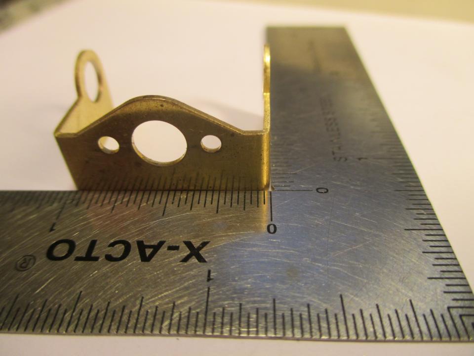
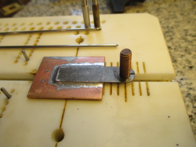
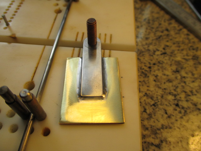
Plan how far your tongue will extend past the 1" wide by 1.3" long, .063 brass chunk. When the flag is rotated about 45 degrees, you want about 3/32 clearance between the rear corners of the flag and the chunk. 

IMG_0431.JPG

Any closer than that and you run the risk of the rear of the brushes contacting it when the car is in a drift :wacko2: 
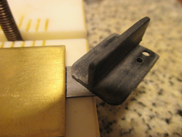
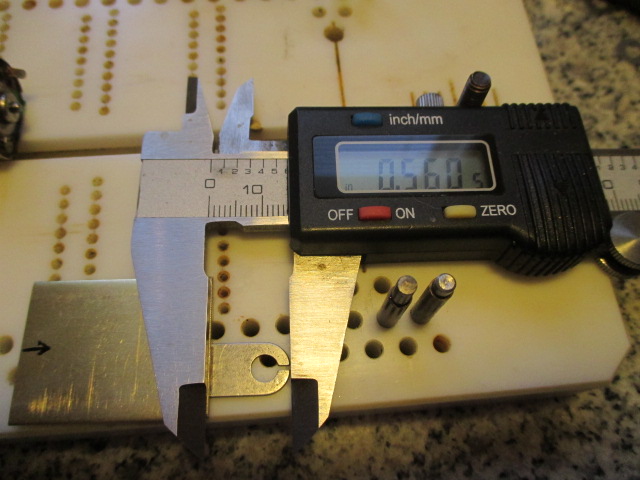
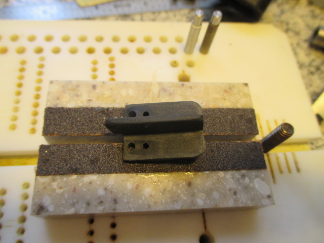
I like these Slick 7 .050 retro steel tongues.  I'm going to Sharpie mark mine on both sides to make the very end of the tongue end up about .56" from the front edge of the chunk.

IMG_0442.JPG


  • Tim Neja likes this

Paul Wolcott


#17 Pablo

Pablo

    Builder

  • Administrator
  • PipPipPipPipPipPipPipPip
  • 18,364 posts
  • Joined: 20-February 06
  • Gender:Male
  • Location:Cleveland, Tennessee

Posted 30 March 2014 - 03:41 PM

I sanded the bottom of the chunk (concave side) on the belt sander a little bit, just barely enough to make it flat.  Once all the metal is fresh, it is flat  :)  Then I finished it with WET 400 wet/dry sandpaper by hand using my flat block. The bottom is now perfect and mikes at about .0615.  Now tin the tongue and the chunk.  Use lots of acid and make sure the solder is flowing wet.  Don't be afraid to lay on quite a bit of solder, you want some excess to flow out when you sandwich them together.  Doesn't even have to be perfectly proportioned because it's all going to level itself out when you float it. Then divide the widths of both the chunk and the tongue in half and scribe the centerlines on both sides of them using your calipers.

IMG_0444.JPG

Those of you who have done this a million times, I apologize for stating the obvious.  If you are a newbie, there are a million ways to do this stuff, this is just what works for me. I use an iron to tin the parts, and a Radio Shack mini-torch to float them home. Once they cool after tinning, bathe both parts in acid again and lay short lines of .032 solder along the sides and rear of the tongue (as sort of a "primer" to get things flowing and ensure you have a nice nest around the edges).  Line everything up on a wood block (you don't want to use a torch on your Rick's Jig), place a small chunk of scrap .063 brass in front of the tongue.  No spacer under the tongue when you solder it up - unlike a Can Am or a F1 car, stocker rules mandate level .050 clearance front and rear therefore no tongue tilt is needed.  Apply gentle, straight downward pressure in the middle of the tongue with some sort of a tool that won't suck up a lot of heat, like an icepick, and hit the works with your torch. Or iron, whatever. I go full throttle on my Radio Shack. Once the solder is flowing and wet, you will feel the push tool drop and the tongue is now floated on, level and straight, I hope ! :D  If not, let cool, apply more acid, and fix it.  If someone has a method of ensuring the alignment always turns out perfect, I'm all ears !  Don't burn down the house with the torch, Bunky ! :shok:

IMG_0450.JPG

If you are sloppy like me, you have some unwanted solder in spots.  We are going to fix that, no worries.  Before you waste effort cleaning it up, measure everything with a fine eye and make sure it's as straight, level, flat and perfect as you want. Mine was within a couple thou and that's good enough for me.  Set the pins and tube spacers on the inner set of the farthest apart 8 holes on your Rick's Jig - this gives the minimum IRRA required WB of 4.5". 

IMG_0452.JPG

Set the tongue screw on the middle, largest, line up front - this gives you the required .75 GL.

IMG_0455.JPG

As a final check to ensure your tongue assembly is perfect, set it on the tongue screw, align your centerline scribe mark with the center of the jig slot, and lay the .078 wire rails alongside the chunk.  Everything should fit like a glove.  Any problems, fix 'em now.  Now that you are sure your tongue assembly is perfect, you can clean it up.  This is a good Dremel attachment to remove solder, a Steube trick:

IMG_0458.JPG

400 wet/dry sandpaper mounted on one of those funky gauze wheels.  They don't last long.  You have to be careful not to gouge your chassis with the screw in the middle of the wheel, but they really take the solder off in a hurry :laugh2:


Paul Wolcott


#18 Bill from NH

Bill from NH

    Age scrubs away speed!

  • Full Member
  • PipPipPipPipPipPipPipPip
  • 14,315 posts
  • Joined: 02-August 07
  • Gender:Male
  • Location:New Boston, NH

Posted 30 March 2014 - 03:56 PM

Slick 7 has been making these spring steel guide tongues for over 20 years. The first ones were for their eurosport chassis kits, but they did sell it separately too. Those first ones weren't .050" thickness, more like about .035". The slot going into the post hole indicates that it's not a stamped piece but has been cut by a laser or EDM cutter, most likely EDM. 


Bill Fernald
 
I intend to live forever!  So far, so good.  :laugh2:  :laugh2: 

#19 Pablo

Pablo

    Builder

  • Administrator
  • PipPipPipPipPipPipPipPip
  • 18,364 posts
  • Joined: 20-February 06
  • Gender:Male
  • Location:Cleveland, Tennessee

Posted 30 March 2014 - 04:04 PM

Tongue assembly complete:

IMG_0459.JPG

IMG_0469.JPG


Paul Wolcott


#20 SlotStox#53

SlotStox#53

    Posting Leader

  • Full Member
  • PipPipPipPipPipPipPip
  • 4,084 posts
  • Joined: 13-March 13
  • Gender:Male
  • Location:TX

Posted 30 March 2014 - 04:18 PM

Some great procedures here Pablo ! Watching & learning as you go :good:

*must buy a mini torch*!!


#21 Pablo

Pablo

    Builder

  • Administrator
  • PipPipPipPipPipPipPipPip
  • 18,364 posts
  • Joined: 20-February 06
  • Gender:Male
  • Location:Cleveland, Tennessee

Posted 30 March 2014 - 04:27 PM

If anybody wants a complete step by step detailed Pablo "cookbook" for using a minitorch, just send me a PM.  It's a lot different than using a gun or an iron and requires special techniques. :wizard:


Paul Wolcott


#22 Bill from NH

Bill from NH

    Age scrubs away speed!

  • Full Member
  • PipPipPipPipPipPipPipPip
  • 14,315 posts
  • Joined: 02-August 07
  • Gender:Male
  • Location:New Boston, NH

Posted 30 March 2014 - 04:31 PM

A couple tips that might help. When floating the tongue use a bamboo chop stick for a hold down. It won't transmit heat to your hand & it's ends can be cut at any angle or shape to facilitate the holding. When marking the centerlines on the guide tongue & front plate, also mark one on the piece of scrap you'll be using under the guide tongue. Line up the marks of the front plate & the piece of scrap. Now you can use the guide post hole & the machined slot that made it to help make sure the guide tongue is on straight.  Those gauze wheels used to back up sandpaper are actually polishing wheels made to be used with ruby polish.


Bill Fernald
 
I intend to live forever!  So far, so good.  :laugh2:  :laugh2: 

#23 SlotStox#53

SlotStox#53

    Posting Leader

  • Full Member
  • PipPipPipPipPipPipPip
  • 4,084 posts
  • Joined: 13-March 13
  • Gender:Male
  • Location:TX

Posted 30 March 2014 - 10:26 PM

I'm with ya so far Pablo :good: Although a possible follow along build of the "Pablo Stocker" is a few cars back in the line of builds to do list :laugh2:


Great stuff & info from yourself ,Mike & Bill .. Will all come in handy in the quest to build plenty 'O cars :D


#24 Half Fast

Half Fast

    Keeper Of Odd Knowledge

  • Subscriber
  • PipPipPipPipPipPipPip
  • 2,615 posts
  • Joined: 02-May 07
  • Gender:Male
  • Location:NYC, Long Island

Posted 31 March 2014 - 11:23 PM

The hallmark of great builders such as Pablo and Mike Katz  is:


R-110.JPG


I am learning much!


Cheers


Bill Botjer

Faster then, wiser now.

The most dangerous form of ignorance is not knowing that you don't know anything!

Never attribute to malice that which is adequately explained by stupidity


#25 Bill from NH

Bill from NH

    Age scrubs away speed!

  • Full Member
  • PipPipPipPipPipPipPipPip
  • 14,315 posts
  • Joined: 02-August 07
  • Gender:Male
  • Location:New Boston, NH

Posted 01 April 2014 - 07:45 AM

Pablo, who is your new friend Bunky? I thought everybody down south was named Billie Joe or Jim Bob. :laugh2:  :laugh2:


Bill Fernald
 
I intend to live forever!  So far, so good.  :laugh2:  :laugh2: 


Electric Dreams Online Shop