Jump to content


Photo

Jail Door: some construction techniques


  • Please log in to reply
8 replies to this topic

#1 Duffy

Duffy

    a dearly-missed departed member

  • Member at Peace
  • PipPipPipPipPipPipPip
  • 3,791 posts
  • Joined: 25-January 09
  • Gender:Male
  • Location:Geographically Brooklyn, Politically Berkeley

Posted 08 June 2014 - 01:47 PM

There may be nothing so useless in these turbulent times as a Jail Door Construction thread. I consider that a challenge.


While I'm working on Chad Brown's "Blarney Castle Dungeon" sled, I figured I'd talk a little about what I think goes into these flimsy vulnerable and utterly charming little shinies. There's actually a pretty carefully considered engineering going into 'em, the way I do 'em, and what with this being the fourth or fifth fastest-growing class in my local RetroEAST™ group, somebody out there may want to look deeper into building one. So here I go.
 

Now, everything in one of these sleds should be as flat and straight as we can get it, as it goes down on and comes off of the jig. Being a Jail Door car, it's never gonna be as straight again, but we can start out with high hopes.


I like to settle my mind and hands at the start of the building session, whatever I'm doing. Blasting in and blasting ahead, all hot and bothered from what-all was happening out there in the Real World, that's a good way to waste your first couple operations. Settle down. OMMMM. Have some coffee. (Sure, it'll get you wired, but first it'll get your throat all warm and happy. Remember it's the first few minutes we need to focus into, after that we'll need the Hyper to push us forward!)


Here's a good first op warmup: the paired rails and crosspieces, done in 6"-plus lengths.


d1.jpg


I've selected and ScotchBrited a nice straight bronze rod, and clipped it into about 7" lengths. You can lay four pieces down on your jig plate (and Harbor Fright sells a cheeeeep granite surface plate that you'd do well to spring for) and roll them back and forth all together, and if any are the least bit bent you will see it instantly when a gap opens up between the bent one and its neighbor.

What you're seeing here in this picture above is the simple holding kloodge I've made for soldering. See, you don't want to put any pressure on the pair of rods as you solder, because you'll impart a curve or twist into them as you move the iron along the length. No good. So you want some way to just rest them with like no stress at all. What I've done is to rest the rods against two pins in my jig plate, then push down my two wire DuffyDogs to move the rods up against the pins right next to the pins; put a dog in the middle, you'll subtly push a curve into the rail. Having them just like a quarter inch inside the pins, the pressure's negligible. They're just resting against the outside rod.


d2.jpg


So now I'm soldering. I've tacked one end together outside and to the left of the left-hand pin and dog, and continued to run the bead for about an inch or more - then I push that bit to the right to get the solder bead inside the pin and dog, and continue. You're seeing me pose for the camera (no, I'm really soldering! Honest!) as I'm midway along the length and moving to the right. As I get near the right-hand pin I slide a little more rod into the working field, and so on.


This results in a very straight and flat rail. 


The droparm center section's another place you want to get right. I make mine with a little "bobbin" I once had the good fortune to make up, inside which the loop, or bale, of rod fits. It's very important that this bale fits neat and doesn't stick out of the bobbin, because any place that sticks out will bind against our favorite guide tongues. So we spend some time getting the bale nice and round and perfect. (It's all right just to root a little out on the inside with a Dremel, but try to get the outside real pretty for the customer!) Again, if pictures aren't too boring, ask and I'll show.


d3.jpg


Here's a pic of the bobbins I like to use in my droparms. These are .38" diameter and undercut to .250" dia. for a bale of 1/16" rod. I like the depth of this groove, as it allows me to completely bury the ends of my fill rods inside the grommet.


It's at this point that I start to measure carefully, making sure my rod stackup is staying inside my allowed space; to save me some major filing and fitting later.


d4.jpg


What you see me doing here is pushing the bale nice and tight into the bobbin as I tack: I've jammed that bar clamp up to the front of the bale, which is restrained by the center post. My right fingers are pressing all the inner rods into the remaining slot in the bale (and that gleeful laughter you hear is my stepson not-taking the shot as he watches steam rise from my fingers). The slot in the bale is tight enough that I can count on the flatness of the finished unit; any other construction - well, come to think of it, any other construction and I wouldn't be talking about all this gobblygook.


So you get the area around the bobbin tacked, then run on out to the end of the droparm. At last, come back and really wet-out the bobbin area to create a solid bronze/solder structure (try to avoid the top and bottom faces, or wick any gops off - you don't want to have to spend a lot of effort re-establishing parallelism of these faces later).


  • MSwiss and Jocke P like this
Michael J. Heinrich
1950-2016
Requiescat in Pace
 
And I am awaiting
perpetually and forever
a renaissance of wonder


#2 Duffy

Duffy

    a dearly-missed departed member

  • Member at Peace
  • PipPipPipPipPipPipPip
  • 3,791 posts
  • Joined: 25-January 09
  • Gender:Male
  • Location:Geographically Brooklyn, Politically Berkeley

Posted 08 June 2014 - 02:12 PM

Here's a little S-bending block for making the kick in the droparm. Like most of what I do, it's a bit of fussiness that you can do away with entirely and be just as happy; I show it here so you can get a sense of what you will need to squeeze the kick, using shims and wires and a vise and cursing. - Listen, you will prevail. You don't need stupid rusty fussies.


d5.jpg


Once the kick is set in, you should go back and hit the droparm again with the soldering iron to eliminate any stress fractures that will occur in this violent bend. 


Now I'll set it aside until later. Get on to setting up the center section.


I'm touchy about brackets. They gotta be Flat Straight and True along with everything else, and they gotta be just about bombproof. Later this month I'm gonna build a Retro sled and I'm gonna go into some detail about my own weird ideas in re: brackets, and it's gonna shall-we-say depart summwatt from some others' thinking. That'll be later. Here, I want as much brass as I can get, but - the R&C '66 rule gives me .047" stock, but I'm lazy and I'll settle for some real nice .040" - it's amazing how much beefier this is than the .032" stuf. The Duffy Firecrotch brackets are made to good tight toleraces (with one glorious goof that HVR's Jim Williams might someday tell you about!) and they're plenty strong. I think I'll use them.


d6.jpg


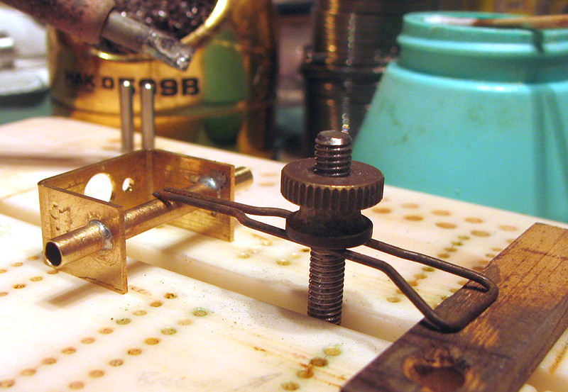
I'm showing my initial setup here so that you may refer back to it tomorrow, as I set this finished assembly in the jig. What's happening here is, I'm centering my pre-cut axle tube in the bracket and clamping it in place, to tack it. Explanation follows.


The tube has been cut to the stackup length - 3" minus tyres, minus two washers, minus a skosh - and I'm getting it right down the middle of the bracket I've already checked for squareness and cheekiness and all. I tack it just enough to keep it in place, but I WON'T really hit the heat to it while that clamp's bearing down on the tube, I can't guarantee that something won't tweak under pressure! 


Just tack, then check all measurements again, including F, S, & T.


d7.jpg


NOW I'll hit it: the little spring clamp here is just a finger that don't burn, that's all. I'll touch solder to one cheek and tube joint on the inside of the cheek, and watch as the solder wicks all the way around the tube on the outside; then do the same on the other side. That's it. This one looks like there's a little more than a neat fillet around the inside, but some of that will wick away as I add the rails in the next stage.


d8.jpg


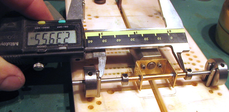
Here's why I tried to get the axle tube just right in the bracket: now I can set it into the gig on its jigwheels, and lock my central position in with axle collars. This way I can remove & replace the work as I need, and it'll all repeat in the jig.


Notice I'm not trusting the axle collars nor the jigwheels to be the same thickness, even tho' they may be: I'm measuring from the solid-est thing on the jig, the pins in their holes, to the collar butting up against the end of the tube. This eliminates as much possible incurred error as I can do. A doublecheck of the bracket cheeks (I fine-tuned the bracket back at the beginning, btw) and I'm ready to start laying in rails.


  • Jocke P likes this
Michael J. Heinrich
1950-2016
Requiescat in Pace
 
And I am awaiting
perpetually and forever
a renaissance of wonder

#3 slotcarone

slotcarone

    Posting Leader

  • Full Member
  • PipPipPipPipPipPipPip
  • 3,975 posts
  • Joined: 23-January 07
  • Gender:Male
  • Location:Dutchess County, NY

Posted 08 June 2014 - 04:54 PM

:) Nice build so far, Duff!!


One thing I have to disagree on is the flimsy part though. I have built probably 15-20 Jail Door chassis for customers and as far as I know the only bend has been the drop arm on Jimmy Williams car. They seem pretto robust to me!!


Mike Katz

Scratchbuilts forever!!


#4 Duffy

Duffy

    a dearly-missed departed member

  • Member at Peace
  • PipPipPipPipPipPipPip
  • 3,791 posts
  • Joined: 25-January 09
  • Gender:Male
  • Location:Geographically Brooklyn, Politically Berkeley

Posted 08 June 2014 - 05:40 PM

Yah, I'm up to #12 or so out there, you musta just got a faster class of customers... no, all seriousness aside, I may SAY 'flimsy' but secretly (well, I just blew that, didn't I?) I agree - everybody complains about how touchy and wimpy these sleds are, but it's just a matter of accepting that you gotta watch 'em after a bad shunt. Dunno about anybody else, but I'm always looking for tweaks when I'm running mine, and routinely re-jigging between races. Most guys do that with everything anyhow, so why the bad rep with Jail Door? (Maybe it's the hint of "recidivism" in the name. I always tho't we'd be better off calling 'em "Retrogate.")


I also do a whole lotta other stuff that Katz don't, all with the conceit that I'm building what I think of as strong or rigid or whatever. It's been shown elsewhere, but I'll talk a little more about my reasoning as this drags out.


Lotsa ways to slam a gate, I guess.


Michael J. Heinrich
1950-2016
Requiescat in Pace
 
And I am awaiting
perpetually and forever
a renaissance of wonder

#5 Duffy

Duffy

    a dearly-missed departed member

  • Member at Peace
  • PipPipPipPipPipPipPip
  • 3,791 posts
  • Joined: 25-January 09
  • Gender:Male
  • Location:Geographically Brooklyn, Politically Berkeley

Posted 08 June 2014 - 10:00 PM

Continuing with all the little fussy bits that might make the thing go. Or not. whatever, I enjoy the fussy stuff.


I do a lot of stuff in my builds that makes sense to meee and maybe nobody else. Might make a difference, might not; and when I become aware of the possible questions I will try to explain my reasoning, for saner people to make informed choices on.


One place this shows up is in my use of big swoopy radii in these rails. There're a couple things going on there: one has to do with how you will see the rails joining with each other and with other components at all manner of angles and distances - because the fewer parallel lines you got, the more rigidity there will be in the structure. Get that? If all the uprights are vertical and parallel to each other, they will all flex the same way and maybe - may-be, I say - allow some floppiness into the sled that we don't need.


On the other hand, maybe we want that flop. Who knows. Up to you.


But there's another reason for the curvy curves: Those big long bends make it easy to adjust in and out a skosh if my uprights weren't exactly the right length, and nobody'll see! Ahhh, sneaky and artistic.


- And i make use of the big curves in another way, which you'll see in a couple minutes.


d9.jpg


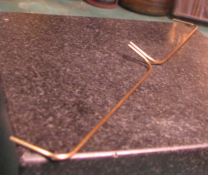
This block started out as a fixture for some forgotten job years back, and was later pressed into service as my vernier-index bendy bendy tool. I can fix differing radius plugs in different lengths and bend up a ton of rails in no time. You can imagine any number of simple setups that will do fine for you. Like most tools, once you envision the idea, the rest is just a matter of improvisation.


Now, I mentioned that I like a lot of self-bracing connections made up of these big curves. I'll also join as many of the rail uprights as I can to my bracket, to sort of tie everything together, and I do this by curling the uprights around to move in or out relative to their adjacent rails and to other components. Since our R&C '66 rules state that all rails must run straight and parallel between uprights, I make sure that all those curls begin after the upright leaves the jig plane - hence, another real good use of big radii! wow, how lucky I made 'em big, huh?


d10.jpg


So, here I'm bending the innermost course of rails to clear the next-out course, with uprights lying up against the inner cheeks AND checking that I'm not accidentally putting in any bends over the long straight part - 

d11.jpg


 - And here I'm checking for matching twist in the forward ends, where I'm starting to angle the uprights for more triangulation.

Now to start to lay everything together. I need some more hands in here:


d12.jpg


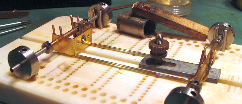
Extra time spent in these first two courses will make the rest of the rail placement a breeze. I've got a wood-block clamp snugged down here to provide some "extra fingers" while I move things around and adjust them for fit and alignment, and I've shimmed out a pair of locator pins for parallelism, since my stackup doesn't correspond to any convenient holes. This clamp will be in place just until the rear uprights are tacked, no more.


d13.jpg


Now the clamp's off, the front uprights tacked; head back and flow the rear uprights nicely, touch a little spot along the length of the rails, and let that breath out you've been holding. Now the motor bracket's angle has been set and you can remove the dummy motor and open up some working space.


d14.jpg


The third course is all cook-the-fingers stuff: just hold gently and tack, same procedure. The little spacer rods between rails are temporary at this stage of construction.


A word more about the curling around of uprights: it should be clear, this stuff don't gotta be how YOU make these sleds. none of this is all hard-fast-rules stuff. What I'm trying to do is to show a way of thinking ahead as you go, planning how the next bit is going to fit and how to accomplish it efficiently.

This third course, for example - its upright is the first to go on the outside of the cheeks, and with a .062" spacer you need to curl the upright back .022" to go up to the .040" cheek. this works out nicely, because the Rules state that no more than two rails may be adjacent to one another, and my build takes advantage of that to get around the bracket cheeks conveniently.


d15.jpg


- And then it gets kinda extreme: I chose to join up the fourth and fifth courses as well, creating two double rails per side, and setting them so that they're on the outsides of the center section's sides to create the most rigid rail I could envision; that meant curling the fourth-course upright waaay around to join up with the cheek. Ain't pretty, but it's the best I could think of.


The fifth course, easy again.


And that's all the tacking. At this point, we can remove and scrub down the sled (but leave the jigwheels in place!), and get the other components ready to go on.


  • Jocke P likes this
Michael J. Heinrich
1950-2016
Requiescat in Pace
 
And I am awaiting
perpetually and forever
a renaissance of wonder

#6 Duffy

Duffy

    a dearly-missed departed member

  • Member at Peace
  • PipPipPipPipPipPipPip
  • 3,791 posts
  • Joined: 25-January 09
  • Gender:Male
  • Location:Geographically Brooklyn, Politically Berkeley

Posted 10 June 2014 - 08:12 AM

Here's MY thinking on JailDoor sleds: they're basically locked-down flat pans, without the pan. The only thing we're allowed motion in is the droparm, and we haven't wanted a moving droparm since before I discovered Ornette Coleman - but it's in the Rules that the droparm "must drop and function as intended by the 1966 designs."


O-kay...the two fuzzy portions, then, are "drop" and "as intended."

Hm.

I intended to shampoo the cat today. I didn't do it; wot, y'think I'm crazy? - But I succeeded in my intent.

Okay. Now, if it moves .001" from top to limit, it's "dropped."

Check, one. Check, two. Droparm, check.


C 03.jpg


Here's my fussy "Parker 51" Art Deco droparm in the making. You can see I've just bent the rod & trimmed it right down to its straight side again, then these get soldered onto the main droparm. It's just a bit of pretty, it does nothing for the function.


C 06.jpg


A good strong guide swing limit is a must on these cars. After having several styles  bend or break away I finally landed on this version, which seems to do well for me. The force of the rotating guide pushes in line with the solder joint, so there's not the tendency to rip it sideways. 


Now let's get back to the center section.


As I laid up the rods for this sled, I made sure that each was as flat and straight as I could get it before I soldered it in; you never want to force an element in and solder it. (If you need reasons, just visit a luthiers' blog and read a few comments.) 


C 02.jpg


Now that the center section's all together, you can check your work at each stage with a little "tap test" - lay the sled on a surface plate (or reasonable substitute) and tap the rails with your fingers. If anything's even a hair off the plane it'll sound.


Then you got a decision: does the rail look bent along its long straight area? Or has it been pulled by its joins with the bracket and front axle tube? If you decide (I won't say things like "must" here, I'm a realist) to fix it, first thing is to try to pop it off the front tube, which is usually easiest, and try to assess if it's sprung by how it originally laid up. If you did a good job of original fitting you shouldn't have any sprung rails, but at this point it's easy enough to check. 


Once you're satisfied with flatness and perfectitude and reallygroovyism in the loose state, you can go in and solder those rails to each other to create the strong integrated structure. I personally believe in the locked-down JD chassis, so I solder all the paired rails solid; you may want to fiddle with selective free distances in the structure for flex; I just don't think we can control it well enough that we can use it as an advantage and not as a potential bend spot in a shunt.


Another tap test after the rail soldering should reveal no new problems - interestingly, I get way more tweaks in piano wire than in bronze with this procedure. In the unlikely event there is anything you can't abide, you may have to resort to brute force. Give it a try. You're already past "perfect," what've you got to lose?


Ad if it's in there for good, know when to let it stay and get on with the next one. The real test is out on the track, and it may be great. The great boatbuilder Pete Culler once wrote of your early attempts: "There will be a lump here and there, and what of it? There'll be a less lumpy one further down the line." weird 


Now there's one more thing at this point: getting the droparm fit perfect.


C 05.jpg


Like I said earlier, MY rail stackup is based on the inside of my .040" bracket, giving me a weird inside aperture that won't match up with any droparm stack. You see the dimensions I end up with here.


But you want your droparm to have no side wiggle, and you don't want to rely on the hinge tube as a limit either - it won't be good enough. So, I put a couple of little bits of rod on the inside of that space, and then I Dremel 'em down to slip-fit clearance with the droparm. That gives me two secure fussy-fit points for my droparm to nest into, the carefully-sized hinge tube and the little chocks up front.


Worst bit's over. Now we put it all together.


Michael J. Heinrich
1950-2016
Requiescat in Pace
 
And I am awaiting
perpetually and forever
a renaissance of wonder

#7 Duffy

Duffy

    a dearly-missed departed member

  • Member at Peace
  • PipPipPipPipPipPipPip
  • 3,791 posts
  • Joined: 25-January 09
  • Gender:Male
  • Location:Geographically Brooklyn, Politically Berkeley

Posted 10 June 2014 - 09:42 AM

Another Duffy-Fussy bit I like is to make my pintubes with a little flange on 'em. It makes it a little easier on the body, and it's a simple little one-step operation to do. I usually make up a lot of these at once and then just keep 'em in a jar for the next build.


C 01.jpg


R-Geo sells neet little grommets in 1/16" and 3/32" ID, a coupla bucks for more than you want. You sweat these onto a 1/16" tube & cut off with extra sticking out, to leave long until your final trim after assembly - cut 'em right to the face, and you will end up with solder inside the hole.


C 07.jpg


Here you see everything all laid out to solder. 


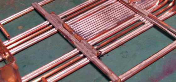
The side rails are held down by my Duffy Dogs, spaced to 3" legal width in the jig. Notice I used cutoffs with bends in them, bits I kept from the rail-bending operation. (- What? you tho't I didn't goof? Anybody say they don't goof is selling something. Oh, wait, I AM selling something. But I'm honest about it.) The reason I use these is to provide a little plier purchase, in the likely event I'll accidentally stick one to my sled in soldering.


The crossbars - another throwback to my boatbuilding days, I gotta resist referring to pan rail and crossbar as AMA and AKA - are just laid over the top of everything and floated in with the solder. Here's another "tap test" moment, as those akas crossbars should be flat & untwisted and the sled should be too. Reality - may be another story. Anyway, float 'em down so that your outer rails are flat.


Another spot you wanna make sure you solder: along the bottom of the bracket cheeks, and under that spot where they emerge from the motor face. The two L-shaped bits, soldered at 90-deg. to the long axis per the Rule, will normally not engage the single middle rod of the third course, but are needed to tie the fourth and fifth into the front of the bracket. This helps keep the bracket-to-sled joint rigid. I'm thinking, tacking the motor in up front would be one more step towards concentrating flex more at that all-important pivot point at motor face. That's probably waaay overthinking. I'm told I do that sometimes.


C 09.jpg


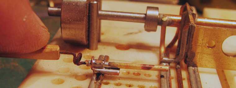
I got a little wire tool I use for attaching pintubes: the pigtail twist is to allow for some bend & give in the lining-up of the pintube in soldering, a way to help my shakey hand press a little more indiscriminately than if I was doing it with pliers or whatnot.

You see little spacers between the rail and the pintube, to raise the mount point up slightly for better durability. Those are offcuts from the rail material. Up front, I lay the pintubes right on the crossbar.


When you solder assemblies that use little bits like this two-rod offcut,there's a risk that the whole thing will melt & come apart. Careful soldering is a way around that, and a couple of failures teach so much. My way is, get everything set in position and the pintube held down with the pigtail tool resting in your fingers which are steadied against the jig plate. Carry a drop of solder to the point of contact between the pintube and the offcut, touch, back off & cool. Now, same thing with offcut-to-rail position. Then, repeat on other side. Lotta acid, touch and get out, four times - the idea is to get that teeny joint done before the heat gets a chance to travel too far and melt something else loose. It IS doable, and with a little practice it's easier to do than describe.


C 08crop.jpg


No shot accurately catches the hinge tube sequence...I'll try and talk through it. 


Put two short bits of 3/32" tube on a long wire. (You can just start out by soldering just one tube all the way across, but in this design I'd have trouble cutting the middle out afterwards, that near to the crossbar; and besides, you want to file the inside face of the tubes nice and square for a good fit with the droparm hinge.) Solder the tubes to the joint of the crossbar first, then go 'round and sweat solder in between the tubes and the rails. Keep your iron away from the tubes' openings and let the solder flow to just-up to those holes, and you probably won't get a stuck assembly.

Then, measure the gap between the tubes and cut & file your droparm hinge tube to just slip inside that gap.


One thing to watch for at this point: when you soldered the crossbar over the area with the droparm spacers, you might have melted one or both out of proper alignment and now the droparm won't fit. That's a risk I take: I want the spacers right where the center section's tied together, to make sure any side load on the droparm is supported in the chassis. Easy fix - and fix it now! It's easy to not see your chassis' floating on the jammed droparm as you solder everything together. Check it out.


Soldering that center tube is a procedure much like what we did in the pintubes - just sweat out a bead along the droparm rods, and it won't wick up and touch the crossarm & freeze everything up. A pass or two with a file in that area of the crossbar where the tube might touch - maybe a good idea, but I like the added support back there, and I am arrogant and believe my skills will carry me through. Sometimes I am proven right.


That's it. A nice overnight pillow-party with Mister Thumler, and -


Df 97 01web.jpg


- And we gots ourselves a couple Vanity Shots.


Df 97 02web.jpg


Hmm. You see something going on here that I haven't tho't to mention yet: 


See how the two crossbars are both one-piece, and the ends of the side rails are unsupported back past the motor face? That's a sneaky little cheat I've been trying out for a couple years, a way to try and get some "flex" in the body mount. It allows just a bit of give in the rear mount location, and may (play that non sequitur gambit, baby!) make for some approximation of "pan" motion. What it certainly does is make for a secure middle-position tie-in of the chassis rails. Ive run this setup for a while, and only recently had to tweak back one rail after a bad shunt. It's actually pretty durable.


There ya go, guys, that's how I make 'em.


Michael J. Heinrich
1950-2016
Requiescat in Pace
 
And I am awaiting
perpetually and forever
a renaissance of wonder

#8 Noose

Noose

    Grand Champion Poster

  • IRRA National Director
  • PipPipPipPipPipPipPipPip
  • 23,243 posts
  • Joined: 08-November 06
  • Gender:Male
  • Location:Denville, NJ

Posted 10 June 2014 - 09:48 AM

And they run very, very well.


Joe "Noose" Neumeister
Sometimes known as a serial despoiler of the clear purity of virgin Lexan bodies. Lexan is my canvas!
Noose Custom Painting - Since 1967
Chairman - IRRA® Body Committee - Roving IRRA® Tech Dude - "EVIL BUCKS Painter"
"Team Evil Bucks" Racer - 2016 Caribbean Retro Overall Champion
The only thing bad about Retro is admitting that you remember doing it originally.


#9 John Streisguth

John Streisguth

    Johnny VW

  • Full Member
  • PipPipPipPipPipPipPipPip
  • 5,638 posts
  • Joined: 20-November 08
  • Gender:Male
  • Location:Bangor, PA

Posted 10 June 2014 - 11:23 AM

Wow, that's super nice Duffy...you've actually inspired me to finally build a new one!  (for which I may curse you later  LOL).


Really, thanks for posting this build.


"Whatever..."


Electric Dreams Online Shop