Jump to content


Photo

IRRA® legal R-Geo Victory 2 F1 kit 2014


  • Please log in to reply
54 replies to this topic

#1 Pablo

Pablo

    Builder

  • Administrator
  • PipPipPipPipPipPipPipPip
  • 18,354 posts
  • Joined: 20-February 06
  • Gender:Male
  • Location:Cleveland, Tennessee

Posted 18 August 2014 - 06:31 PM

Finished September 2014:

post-91-0-79579700-1410958914.jpg


post-91-0-47403500-1410958903.jpg


Here's how it all started:

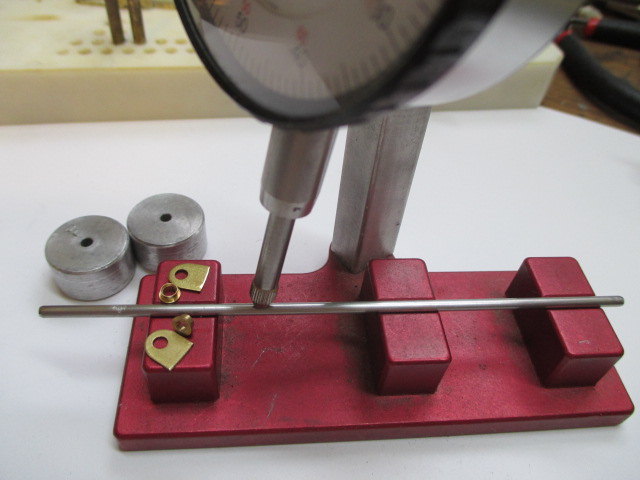
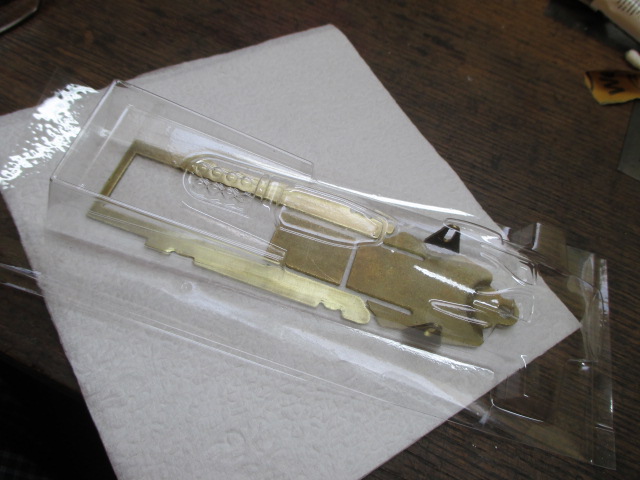
My racing buddy won a Rgeo Victory 2 kit as a race prize and I was chosen to build it :)

The first thing I did was grab a Chicagoland McLaren IRRA legal F1 body to use as the planning standard.  WB 4", GL 1".

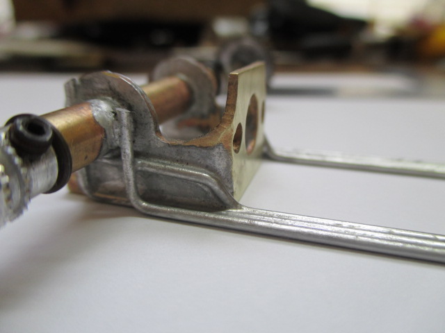
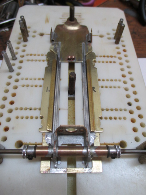
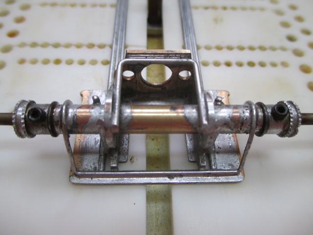
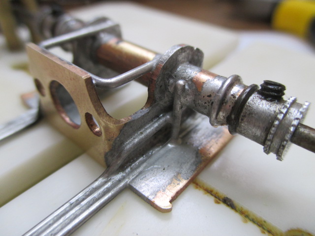
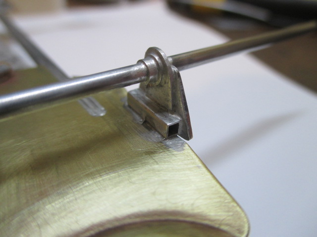
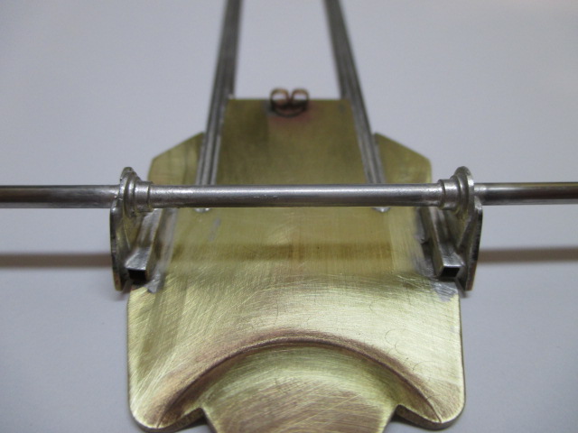
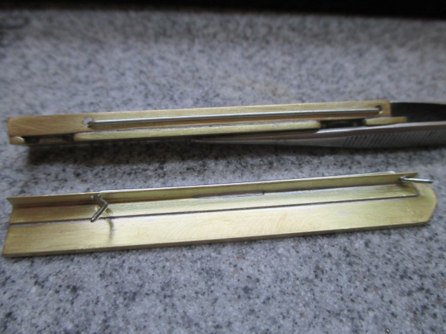
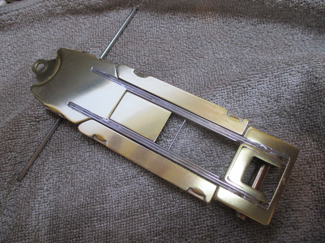
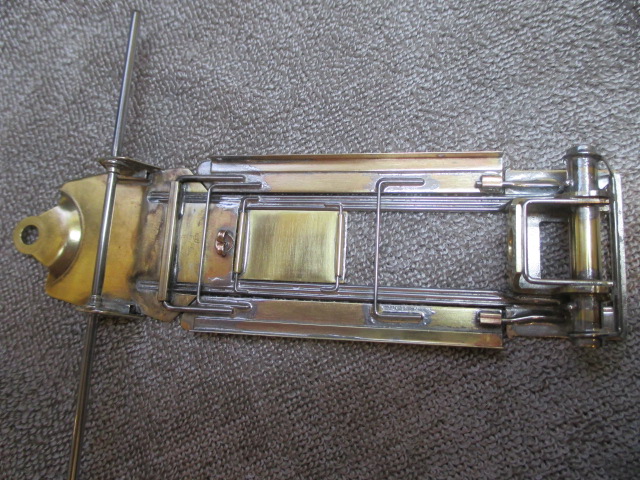
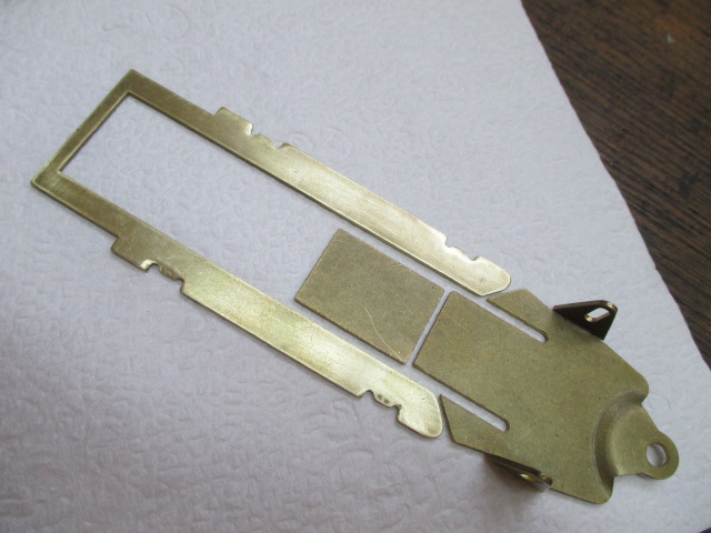
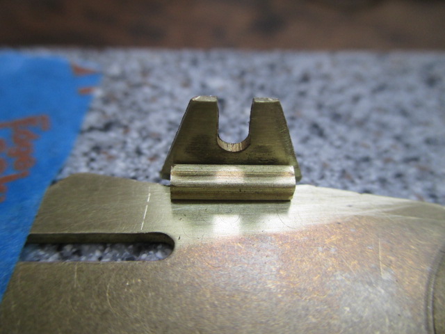
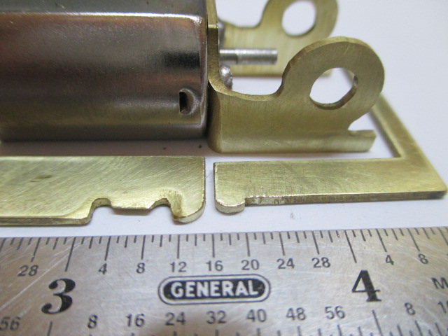
The front axle uprights need to be bent inward and trimmed on top to preclude conflicts with the body.  I don't see that as a problem, but I haven't done it yet.  The body mount tabs on the pans are very tall and not to my liking so I cut them off and shaved the pans flat where they used to be. I'm going to use 2" JK Indy body clips.  Everything else looks like a piece of cake. Kudos to Rick Bennardo, the design is very nice and I'm sure this thing is going to handle great, no matter how badly I screw it up :crazy:

IMG_1829.JPG

IMG_1827.JPG


  • One_Track_Mind and Peter Horvath like this

Paul Wolcott


#2 Bud Greene

Bud Greene

    On The Lead Lap

  • Full Member
  • PipPipPipPip
  • 469 posts
  • Joined: 12-February 11
  • Gender:Male
  • Location:Saraland, AL

Posted 18 August 2014 - 06:44 PM

I will be watching


#3 SlotStox#53

SlotStox#53

    Posting Leader

  • Full Member
  • PipPipPipPipPipPipPip
  • 4,084 posts
  • Joined: 13-March 13
  • Gender:Male
  • Location:TX

Posted 18 August 2014 - 07:01 PM

Great start Pablo :good:   That F1 kit looks a nice piece, as does that Chicagoland body with some crisp lines & detail :)


Will be watching as well.


#4 Pablo

Pablo

    Builder

  • Administrator
  • PipPipPipPipPipPipPipPip
  • 18,354 posts
  • Joined: 20-February 06
  • Gender:Male
  • Location:Cleveland, Tennessee

Posted 20 August 2014 - 02:47 PM

The Rgeo front end is flat right out of the bag, and the coined tongue is tilted perfectly.  The uprights are now sliced off to be level with the top of the axle and both sides are narrowed from .050 to about .042.  I relieved/enlarged the manufacturing notches with a thin cutting wheel, then tilted them inboard at 5 degrees from vertical to allow body movement without conflict.

IMG_1854.JPG


Hollow square brass tubing pieces will brace them.  Also, I plan on making .032 wire braces that snake over the top of the axle and down both edges.

IMG_1857.JPG


  • Peter Horvath likes this

Paul Wolcott


#5 Bill from NH

Bill from NH

    Age scrubs away speed!

  • Full Member
  • PipPipPipPipPipPipPipPip
  • 14,274 posts
  • Joined: 02-August 07
  • Gender:Male
  • Location:New Boston, NH

Posted 20 August 2014 - 10:06 PM

What is the purpose of thinning the front uprights .008? What does doing that give you? Anything other than perfectly flat uprights that will bend in the 5 degrees easier?


Bill Fernald
 
I intend to live forever!  So far, so good.  :laugh2:  :laugh2: 

#6 SlotStox#53

SlotStox#53

    Posting Leader

  • Full Member
  • PipPipPipPipPipPipPip
  • 4,084 posts
  • Joined: 13-March 13
  • Gender:Male
  • Location:TX

Posted 20 August 2014 - 10:25 PM

Bill , from what I read Pablo did the "thinning" and bending to allow the uprights to fit underneath the Chicagoland McLaren body, plus allow the side pans/chassis with body attached to clear the uprights when flexing/shaking etc ....  :good:   :)


#7 Pablo

Pablo

    Builder

  • Administrator
  • PipPipPipPipPipPipPipPip
  • 18,354 posts
  • Joined: 20-February 06
  • Gender:Male
  • Location:Cleveland, Tennessee

Posted 21 August 2014 - 07:50 AM

Exactly.  I knew they needed to be bent inward a little, but 1. I wanted em thinner so they would bend without bending the nosepiece  2. Saved a little weight high up 3. The thinner they are on the outside the less I would have to bend them.  So I shaved em until I got to a point where I consider them still plenty strong enough.


  • Jaak likes this

Paul Wolcott


#8 Pablo

Pablo

    Builder

  • Administrator
  • PipPipPipPipPipPipPipPip
  • 18,354 posts
  • Joined: 20-February 06
  • Gender:Male
  • Location:Cleveland, Tennessee

Posted 30 August 2014 - 01:56 AM

I've been studying the latest retro F1 chassis works of the Masters here on Slotblog.  My original plan was to leave the RGeo pans connected in the rear as one piece, but changed my mind.  I cut the pans at the face of the bracket, and narrowed the nubs on the rear piece from 1.625 to about 1.460 so they won't interfere with the body:

IMG_1870.JPG

IMG_1871.JPG


The RGeo motor bracket was the best I've seen yet.  A little tweaking and a trip to the disc sander to face the sides was all it took to make it perfect.  The photons showing at the rear are because I purposely tapered both sides up a hair:

IMG_1872.JPG


All parts wet sanded with 800 grit. The devil is in the details, Bunky. :)  Everything has to lay flat:

IMG_1873.JPG


  • Jaak and Peter Horvath like this

Paul Wolcott


#9 Pablo

Pablo

    Builder

  • Administrator
  • PipPipPipPipPipPipPipPip
  • 18,354 posts
  • Joined: 20-February 06
  • Gender:Male
  • Location:Cleveland, Tennessee

Posted 30 August 2014 - 05:08 AM

I prefer tubing on my motor brackets, so I reamed the holes with a Unibit to 7/32".

Chicagoland F1 bracket brace soldered in place.

IMG_1883.JPG


Tongue faced (both sides) with Magnehone.

IMG_1879.JPG


  • Jaak and Peter Horvath like this

Paul Wolcott


#10 Pablo

Pablo

    Builder

  • Administrator
  • PipPipPipPipPipPipPipPip
  • 18,354 posts
  • Joined: 20-February 06
  • Gender:Male
  • Location:Cleveland, Tennessee

Posted 31 August 2014 - 03:28 PM

Rgeo jig wheels, earring clutch, dummy axles centered, rear axle tube 1.50", bracket holes hogged out and countersunk.

WB 4.00", GL 1.00"  Next step is going to be a learning experience for me - the rail gaps in the .050" nosepiece are about .094, so twin .047 rails just seem logical.  That leaves a (theoretical) 3 thou gap to allow a little solder to pool. Uncharted territory scares me but only one way to find out....... :on_the_quiet2:   Jay Guard, thanks for your "sanity check phone consult" about this build last week......let's see if I can pull it off...... :o


IMG_1894.JPG


  • Jaak and Peter Horvath like this

Paul Wolcott


#11 Pablo

Pablo

    Builder

  • Administrator
  • PipPipPipPipPipPipPipPip
  • 18,354 posts
  • Joined: 20-February 06
  • Gender:Male
  • Location:Cleveland, Tennessee

Posted 01 September 2014 - 12:21 PM

Trying to be CMF3 :laugh2:

I like the feel of the twin .047 rails so far, but it needs more stiffness.

IMG_1909.JPG


  • Jaak likes this

Paul Wolcott


#12 Pablo

Pablo

    Builder

  • Administrator
  • PipPipPipPipPipPipPipPip
  • 18,354 posts
  • Joined: 20-February 06
  • Gender:Male
  • Location:Cleveland, Tennessee

Posted 02 September 2014 - 12:44 PM

IMG_1917.JPG

IMG_1924.JPG


Triple .047 rails.  When I flex it with my meaty fingers, it feels like an .025 C11. If John feels the need to stiffen it, he can tack solder little pieces of .032 wire to the front of the motor and connect them to the rails.  That will stiffen it considerably. :)


  • Jaak and Peter Horvath like this

Paul Wolcott


#13 Pablo

Pablo

    Builder

  • Administrator
  • PipPipPipPipPipPipPipPip
  • 18,354 posts
  • Joined: 20-February 06
  • Gender:Male
  • Location:Cleveland, Tennessee

Posted 03 September 2014 - 12:14 AM

RGeo pans blueprinted and widths narrowed from .345" to .325".  The 15 thou brass angle pieces just give the proper rail clearance.  Hoping for a final width of about 1.615.  Rear piece is tack soldered only at this point.  Next challenge is going to be a .650" wide, 15 thou brass floating center weight.

IMG_1930.JPG


  • Jaak likes this

Paul Wolcott


#14 Pablo

Pablo

    Builder

  • Administrator
  • PipPipPipPipPipPipPipPip
  • 18,354 posts
  • Joined: 20-February 06
  • Gender:Male
  • Location:Cleveland, Tennessee

Posted 03 September 2014 - 04:45 PM

Since the Koford 28 crown is narrower than the Parma, it allows enough clearance for wire braces inside the .750 bracket. The Parma will only allow .032 wires; the Koford will allow .055 and maybe even .063.  Bracket brace wires are all .047 except for the rear .032 tubing brace.  Do you think I'm underbraced, or overbraced ?  :)

IMG_1934.JPG

IMG_1936.JPG


  • Jaak likes this

Paul Wolcott


#15 Pablo

Pablo

    Builder

  • Administrator
  • PipPipPipPipPipPipPipPip
  • 18,354 posts
  • Joined: 20-February 06
  • Gender:Male
  • Location:Cleveland, Tennessee

Posted 03 September 2014 - 06:02 PM

Piano wire front axle is tinned and reasonably straight.  Rgeo jig wheels, Chicagoland keepers, and a pair of .025 holder thingies I made for the uprights.

IMG_1949.JPG


  • Jaak likes this

Paul Wolcott


#16 Pablo

Pablo

    Builder

  • Administrator
  • PipPipPipPipPipPipPipPip
  • 18,354 posts
  • Joined: 20-February 06
  • Gender:Male
  • Location:Cleveland, Tennessee

Posted 03 September 2014 - 07:25 PM

IMG_1955.JPG


IMG_1959.JPG


  • Jaak and Peter Horvath like this

Paul Wolcott


#17 redbackspyder

redbackspyder

    Renegade, Mutineer

  • Full Member
  • PipPipPipPipPipPipPip
  • 2,995 posts
  • Joined: 09-January 08
  • Gender:Male
  • Location:Rowland Heights, CA

Posted 03 September 2014 - 09:28 PM

Pablo, can I ask a really stupid question ?   Why do you need such huge bracing on the motor bracket ???  Do you guys take such hard hits that it is that necessary , and is that not a lot of weight up high ?  I really am curious, because I see so many people out here that just run straight ball bearings in the bracket, put in with Red Loc-tite, and never a problem, and reduces weight...  


Mill Conroy
 

AKA : TWO LAP CONROY, Anointed Trigger Monkey by Mike Swiss


Deal me life's toughest cards, without chance for hope nor fame, just let me play this one last hand, and I'll win this whole damn game.

Second Most Interesting Man in the World.


#18 Pablo

Pablo

    Builder

  • Administrator
  • PipPipPipPipPipPipPipPip
  • 18,354 posts
  • Joined: 20-February 06
  • Gender:Male
  • Location:Cleveland, Tennessee

Posted 03 September 2014 - 10:27 PM

Sure, Mill. :)

Your questions are smart. I did ask for opinions on bracing, so I don't consider anybody who reads the English language "stupid".  :)

1. You are 100% correct in your thinking - my bracket is probably over braced.  Look at my build history - everything I do is "overbuilt". Minimum IRRA weight for an F1 is 100 grams. I agree with you, high up weight is bad. But, don't be fooled by my cheap camera, there is really not much "high up weight" there.  The pics were close ups.  The wires may look huge in the pics, but everything is .047, except for the .032 wraparounds on the tubes :D

2.  When I build things for customers and friends, it has to be strong, and redundant. There can be no failures.

3.  Yes, we take "hard hits".  When you race on tracks where most of the racers have never been, there will be hard crashes.

4.  The light weight chassis you guys run at BP (different rule set than IRRA) are a completely different animal than an IRRA legal car.

5.  "Never a problem"    Of  course there is never a problem at BP, Mill.  No newbies.  Like Jimmy Johnson driving next to Jeff Gordon.

As opposed to Jeff Gordon running next to Bunky at 197 MPH :

Bunky.jpg


Hope that satisfies your curiosity, and no disrespect whatsoever, Mill. :)


  • Jaak likes this

Paul Wolcott


#19 bluecars

bluecars

    Checkered Flag in Hand

  • Full Member
  • PipPipPipPipPipPip
  • 1,273 posts
  • Joined: 26-June 13
  • Gender:Male
  • Location:Tuskegee, AL

Posted 03 September 2014 - 10:46 PM

:crazy: I'm not falling for that again. I saw what happened when I gave my opinion on something you already soldered in. :crazy:


  • Jaak likes this

Robert "Red" Valantine :diablo: 


#20 Bill from NH

Bill from NH

    Age scrubs away speed!

  • Full Member
  • PipPipPipPipPipPipPipPip
  • 14,274 posts
  • Joined: 02-August 07
  • Gender:Male
  • Location:New Boston, NH

Posted 04 September 2014 - 08:00 AM

"Tis better to remain silent & be thought a fool, than to open your mouth & remove all doubt." :laugh2:  :laugh2:  Ben Franklin may have said this.


  • Jaak likes this
Bill Fernald
 
I intend to live forever!  So far, so good.  :laugh2:  :laugh2: 

#21 redbackspyder

redbackspyder

    Renegade, Mutineer

  • Full Member
  • PipPipPipPipPipPipPip
  • 2,995 posts
  • Joined: 09-January 08
  • Gender:Male
  • Location:Rowland Heights, CA

Posted 04 September 2014 - 10:37 AM

Pablo, the only reason that I brought it up, they have run many enduros using the Warmack bracket with just bearings in the rear and aluminum axle spacers, and never lost a bearing yet...  I am sure that because of the variance in tracks that your cars out East are not harmed by the additional weight,  whereas out here, the cars are lighter..  Just an interesting observation, beautiful chassis by the way


Mill Conroy
 

AKA : TWO LAP CONROY, Anointed Trigger Monkey by Mike Swiss


Deal me life's toughest cards, without chance for hope nor fame, just let me play this one last hand, and I'll win this whole damn game.

Second Most Interesting Man in the World.


#22 Pablo

Pablo

    Builder

  • Administrator
  • PipPipPipPipPipPipPipPip
  • 18,354 posts
  • Joined: 20-February 06
  • Gender:Male
  • Location:Cleveland, Tennessee

Posted 04 September 2014 - 02:18 PM

Yes, I'm well aware lots of people use bearings in the bracket with big spacers and that works fine.  I wouldn't be worried about the bearings - with the 3.250 F1 width I'd be concerned that is a lot of axle hanging out in the breeze waiting to snap a drill blank.  But it doesn't seem to happen. Both methods work. One thing is for sure, next Can Am I build with the super wide Chicagoland bracket will be sans tubes.  


I'm also aware your rules don't mandate minimum weight, so of course they are lighter.


Thanks for the comments and compliment.  To my eyes, it looks ugly until it comes out of the tumbler.  This is only a workhorse, not a vintage masterpiece.   :)  


Paul Wolcott


#23 Pablo

Pablo

    Builder

  • Administrator
  • PipPipPipPipPipPipPipPip
  • 18,354 posts
  • Joined: 20-February 06
  • Gender:Male
  • Location:Cleveland, Tennessee

Posted 04 September 2014 - 10:39 PM

More front axle bracing:

IMG_1967.JPG

IMG_1970.JPG


  • Peter Horvath likes this

Paul Wolcott


#24 Pablo

Pablo

    Builder

  • Administrator
  • PipPipPipPipPipPipPipPip
  • 18,354 posts
  • Joined: 20-February 06
  • Gender:Male
  • Location:Cleveland, Tennessee

Posted 13 September 2014 - 11:56 AM

Brass angles installed and .055 holes drilled for 2 inch JK Indy clips.  The front bends in the clips are bent to the inside to make them easy on/easy off, and the tips are sharpened.

IMG_1988.JPG


  • Jaak likes this

Paul Wolcott


#25 SlotStox#53

SlotStox#53

    Posting Leader

  • Full Member
  • PipPipPipPipPipPipPip
  • 4,084 posts
  • Joined: 13-March 13
  • Gender:Male
  • Location:TX

Posted 13 September 2014 - 12:20 PM

It's all in the details :)  Very neat work as usual Pablo :good:


Nice to see a build using the body clips , what do you find the best to use overall , clips or regular pins & tube?


Electric Dreams Online Shop