Jump to content


Photo

Step-by-step FT16D motor rewind/build


  • Please log in to reply
24 replies to this topic

#1 havlicek

havlicek

    OCD Rewinder

  • Subscriber
  • PipPipPipPipPipPipPipPip
  • 11,198 posts
  • Joined: 20-August 07
  • Gender:Male
  • Location:NY

Posted 14 December 2014 - 02:42 PM

I haven't done one of these for a while, so I figured now's as good a time as any. I got a motor recently from Joe Lupo that was in fairly good condition (especially compared to how these things are lately!), so that will be the example motor.
 
As you can see, it's a typical Mabuchi FT16D (can drive). It even has a usable set of Mabuchi leads and both the can and the end bell are in OK shape. Hooking it up, it runs... and that's about all you can say about these things.
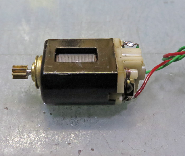
 
h1a.jpg
 
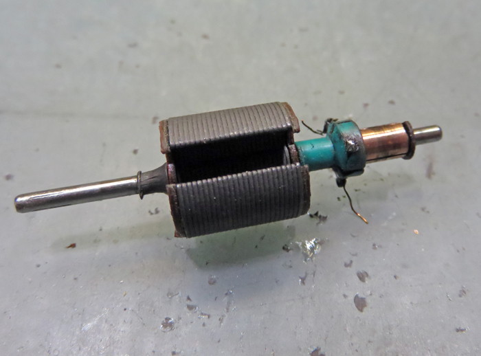
Taking the motor apart, you have your standard 110 turns of really skinny wire (#32?) and the Mabuchi stack and comm. I typically throw away the springs and brushes, and that'll be the case here as well. The brushes show some wear (although not too bad), but new ones are a good investment, and those stock springs are awful... barely supplying enough pressure on the small brushes to keep them in good contact with the comm on even the stock wind.

h2a.jpg
 
Stripping all the wire off the arm, you wind up with a pretty normal looking stack made up of .014" thick lams, insulated on both ends with fiber pieces, the junk Mabuchi comm that I almost always toss (unless someone REALLY needs things to be stock for some reason), and the Mabuchi steel tail spacer that is guaranteed to cause shorts if the magnet wire rubs against it... so that, the comm and the fiber stack-end insulators all get tossed. The shaft, while not pristine on the drive end, is surprisingly straight, so I'll keep that and polish it a bit to smooth out what's left of the splines.
h3a.jpg
 
So first off, I swapped the stock comm for a replacement Tradeship one. The Tradeship has a phenolic "tail" that's kinda wide, and to make more room for winding, I shortened that and tapered off what was left of it. I then cut comm and tail spacers from brass tubing with approximately a 2mm ID.  These are of a length to both center the arm in the field, and to make up for losing the fiber stack-end insulators (each of which is thicker than a lam).  The new comm spacer and shortened com phenolic tail, will both help to make for a substantial increase in winding room.

This Tradeship com also has a built-in timing advance in the CW direction (ie: the tabs are NOT centered on the comm segments). Obviously, you can still advance the com timing in the standard CCW direction (using the comm slots instead of the tabs for spotting the timing), but that puts the tabs in an awkward position for winding, tieing, and finishing the arm. On this motor, I left everything and just went with the CW timing advance. Generally speaking, these motors will wind up going into a chassis with an "inline" motor configuration, so it's a simple matter of just installing the crown on the other side of the pinion gear.
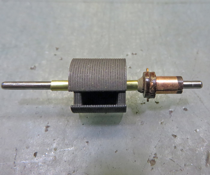
 
h4a.jpg
 
With all the attention having been paid to the arm, it was time to spruce up the can a bit. So I stripped the can down, polished up the bushing carrier, and got it ready for paint... also drilling and countersinking the can for endbell retaining screws.
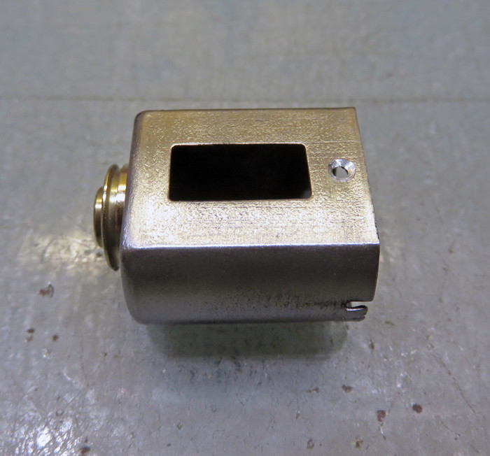
h5a.jpg
 
Meanwhile... the can got a fresh coat of orange paint, a very "Mabuchi" color instead of doing something more "different". Also, the arm went into the "powder coating department" (ie: the garage) and got a nice coat of 3M powder. I also polished up the shaft as best as I could without reducing the shaft diameter significantly; that'll be important when it's time to balance the arm.

We're ready to start actually making a motor!
 
h6a.jpg

h7a.jpg
 
For this motor, the arm got a 65t/30 wind done "backwards" and, while not especially pretty to look at, it WILL be a runner!

h8a.jpg
 
Time to mix up a batch of high-temp epoxy, tie the arm, and preheat the arm to make sure the epoxy penetrates the arm as completely as possible.
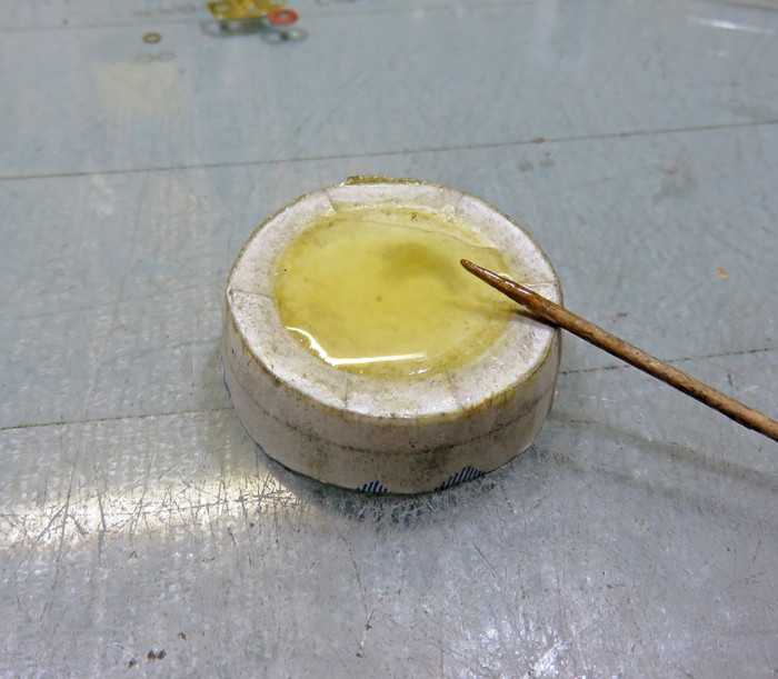
 
h9a.jpg
 
Starting the assembly of the finished motor, I made up a pair of .004" steel shims. While a total of .008" reduction in the "hole" doesn't sound like much, it's a good number for these motors. First off, it's not so much that the magnet tabs need to be flattened. Second, it is enough to make a significant difference in performance. Third, you really don't want such a tight setup in these old motors... unless you're going "all the way" and will be modifying the endbell against heat problems.
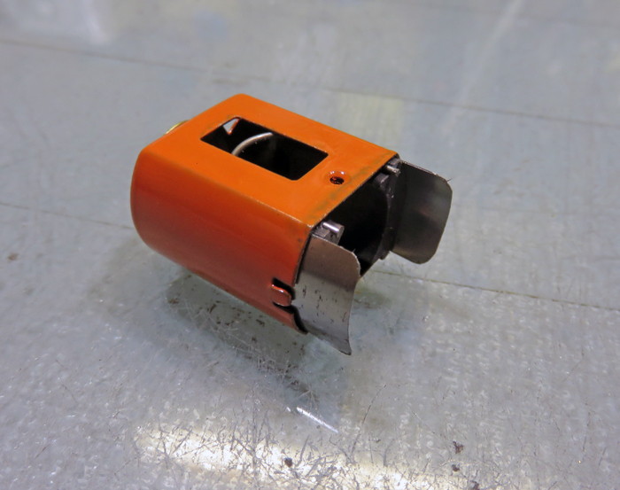
 
h10a.jpg

h11a.jpg
 
With the arm tied and epoxied... fresh out of the oven from speed-curing, we're getting closer to having an finished motor.
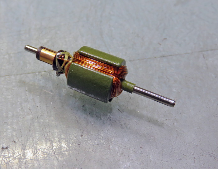
h12a.jpg
 
Next step is to remove the cured powder coating from the outside of the arm. While it doesn't cause any problems just "being there", it does add rotating mass to the arm and in a tight setup, it increases the OD of the arm to the point where it will hit the magnets... a real no-no. So, of course, this needs to be done before balancing, as well as cutting the comm, another important step to getting the motor to run best as possible and reduce "brush bounce".

h13a.jpg
 
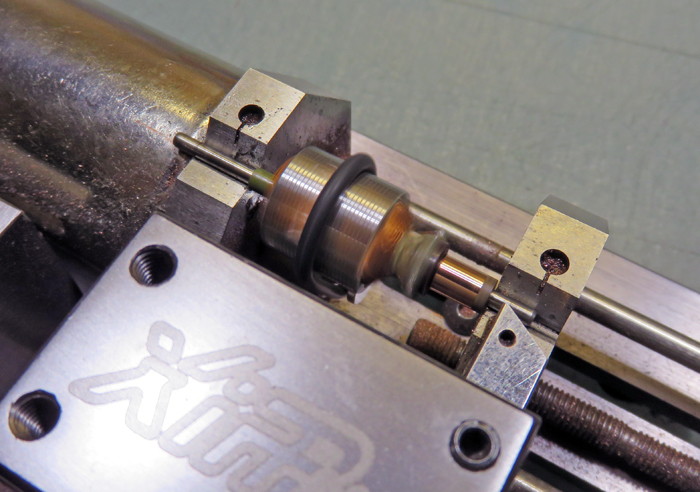
... speaking of cutting the comm:

h14a.jpg
 
It's also a good idea to keep checking for problems along the way to avoid wasting time and effort on subsequent steps if a problem should arise. The last time I check is right before final assembly, and the arm meters "dead-bang on" at .615 ohms. This arm will be a big-time improvement over the stock arm, and the other improvements will make for a sweet runner.

h15a.jpg
 
In most cases, I'll do a static balance on mild winds. If the shaft is good, and you invest the time and effort, you CAN do a plenty good enough job for these kinds of motors. I wouldn't expect this to work well enough with hotter motors, but here... it's all good. The arm balanced up with no problem thanks to my R-Geo balancing block and a set of straightedge blades.
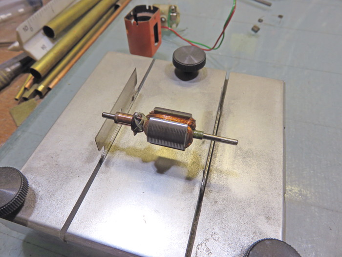
 
h16a.jpg
 
Of course, if you're proud of all the work you've done (and as you can see... it IS a lot of work!), it's time to "sign" your work. That way, years from now people will look at the arm and say... "What a jerk that Havlicek was for wasting all that time on such a goofy old motor!" :D
 
h17a.jpg
 
After carefully spacing the arm to be centered in the field (another really important step), and putting the motor together, I wound up a pair of new stainless steel springs from .015" wire. This one little tidbit will also result in a big improvement in performance... especially with the new wind. After that, a set of new brushes were installed making sure they don't hang up in the hoods (a motor-killer), both ends were oiled LIGHTLY and time to give her a spin on the power supply. Well, this motor is much faster than I would have even guessed and smooth as all get-out to boot. It draws just about an amp and doesn't at all get alarmingly warm. This old Mabuchi has a whole new lease on life, and one where it will run rings around its former self, but still be entirely appropriate for a period chassis/car. The endbell itself was fine... albeit a little grungy, but that adds "authenticity" or "patina", right?   :D
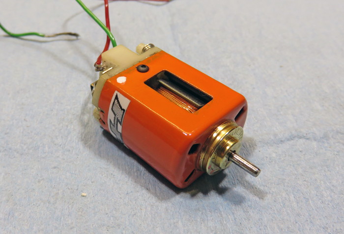
h18a.jpg

PS: Cheers to Joe Lupo for furnishing a clean motor to work on. Joe has 'the good stuff"!   :)
 
-john
  • Cheater, slotbaker, MSwiss and 3 others like this
John Havlicek


#2 Steve Deiters

Steve Deiters

    Posting Leader

  • Full Member
  • PipPipPipPipPipPipPip
  • 2,288 posts
  • Joined: 28-May 07
  • Gender:Male
  • Location:Cincinnati, OH

Posted 14 December 2014 - 03:11 PM

Very interesting, John!
  • havlicek likes this

#3 havlicek

havlicek

    OCD Rewinder

  • Subscriber
  • PipPipPipPipPipPipPipPip
  • 11,198 posts
  • Joined: 20-August 07
  • Gender:Male
  • Location:NY

Posted 14 December 2014 - 03:11 PM

Thanks, Steve.   :)
 
-john
John Havlicek

#4 slotbaker

slotbaker

    Dan Gurney Fan

  • Subscriber
  • PipPipPipPipPipPipPip
  • 2,694 posts
  • Joined: 16-February 06
  • Gender:Male
  • Location:Sydney, Australia.

Posted 14 December 2014 - 03:21 PM

Once again, nice doco.

Thanks for taking the time to put it together and share with us.

:good:

Steve King


#5 havlicek

havlicek

    OCD Rewinder

  • Subscriber
  • PipPipPipPipPipPipPipPip
  • 11,198 posts
  • Joined: 20-August 07
  • Gender:Male
  • Location:NY

Posted 14 December 2014 - 03:26 PM

ALWAYS a pleasure, Steve.  

I have to admit that it's not for purely altruistic reasons that I sometimes do these things. Now that I sell a bunch of these, I think it's important to show just what goes into bringing these motors back to life. Even a "simple" build like this one represents a lot of work, supplies, and of course a history of learning from failure.  

Then again, this place is THE online resource for all-things slot-related, so what better place to put this!
 
-john
  • slotbaker, Keith Moister, Samiam and 2 others like this
John Havlicek

#6 slotbaker

slotbaker

    Dan Gurney Fan

  • Subscriber
  • PipPipPipPipPipPipPip
  • 2,694 posts
  • Joined: 16-February 06
  • Gender:Male
  • Location:Sydney, Australia.

Posted 14 December 2014 - 06:14 PM

John, I'm sure you've covered this before, but I can't track it down.
 
How do you apply the powder?
 
Normally, it's attracted to, and held on the job electrostatically.
 
Just curious.

:huh:

Steve King


#7 havlicek

havlicek

    OCD Rewinder

  • Subscriber
  • PipPipPipPipPipPipPipPip
  • 11,198 posts
  • Joined: 20-August 07
  • Gender:Male
  • Location:NY

Posted 14 December 2014 - 06:38 PM

Hi Steve,
 
The process you describe is only one way that powder coating is applied. That way "can" work here as well, but it creates some difficulties that make it less satisfactory for slot car armatures. I actually tried that early on, and while it DID work, it produced a coating that was thin (and thinner IS better to a point) to the point where it didn't seem as it would be a reliable anti-short measure.

Powders are also formulated for "fluid bed" application, and that is what I (and I think others as well) do. Basically, the arm is preheated to a certain temp, and then dipped-and-twirled quickly into the powder that is being "boiled" by flowing air through it via a permeable membrane. The powder actually looks and acts like a boiling liquid when you figure out a good membrane as well as a good air pressure.  

Powders meant for electrostatic application will produce a film thickness that's WAY too heavy when applied by fluid bed (I've tried :D ), and I assume that powders meant for fluid bed application would produce a lousy film if applied electrostatically.  

As an aside, electrostatic powders aren't usually available in higher-temperature ratings, although there are some out there.  
 
-john
  • slotbaker likes this
John Havlicek

#8 SlotStox#53

SlotStox#53

    Posting Leader

  • Full Member
  • PipPipPipPipPipPipPip
  • 4,084 posts
  • Joined: 13-March 13
  • Gender:Male
  • Location:TX

Posted 14 December 2014 - 06:44 PM

Excellent how-to, John. :)

Have looked into the fluid bed process... may get into this once I try winding and also have more space to store the 3M powder. :laugh2:

See if I achieve good winding so it's worth investing in the powder. :good:
  • havlicek likes this

#9 havlicek

havlicek

    OCD Rewinder

  • Subscriber
  • PipPipPipPipPipPipPipPip
  • 11,198 posts
  • Joined: 20-August 07
  • Gender:Male
  • Location:NY

Posted 14 December 2014 - 06:51 PM

Well, there's no reason to get into powder-coating to try winding, Paul. Just leave those fiber stack-end insulators on there and watch for shorts. I used to epoxy them onto the stack ends using small battery clips as clamps. When the epoxy set up, I would trim them flush with the stack to get as much room as possible.

The wire is most likely to short on the sharp 90 degree edges between the stack inside and the top and bottom. The stack insulators do the most good at those points. They are also made to be slightly "proud" of the actual lams to add protection, and that cuts down on space, which is why I used to trim them.
 
-john
John Havlicek

#10 wbugenis

wbugenis

    On The Lead Lap

  • Full Member
  • PipPipPipPip
  • 330 posts
  • Joined: 17-December 09
  • Gender:Male
  • Location:Brooklyn, NY

Posted 14 December 2014 - 06:52 PM

You guys who express interest in making armatures have no excuse with all the instruction and materials available to you today.
 
How to make a fluid bed on YouTube:
 

  • slotbaker and havlicek like this
William Bugenis

#11 havlicek

havlicek

    OCD Rewinder

  • Subscriber
  • PipPipPipPipPipPipPipPip
  • 11,198 posts
  • Joined: 20-August 07
  • Gender:Male
  • Location:NY

Posted 14 December 2014 - 07:03 PM

Ha Bill!... so true!
 
-john
John Havlicek

#12 CafeBikeGirl

CafeBikeGirl

    Rookie Keyboard Racer

  • Full Member
  • Pip
  • 14 posts
  • Joined: 07-December 14
  • Gender:Female
  • Location:SC

Posted 14 December 2014 - 07:37 PM

A general problem with electrostatic applied coatings  is that the media will get attracted to the nearest and sharpest surfaces first (same thing with electroplating as well), basically the opposite of aerosols which have a tendency to accumulate in pockets and be thin on corners.

With something shaped like an armature it would be very difficult to get the coating on the inside where you want it. This can sometimes be overcome by doing your first initial spray at a low voltage setting (for a slot car armature probably way less than 5 KV which is the lowest setting on my gun). After the low areas are sprayed then you can bump the voltage up to cover the high areas.

Most off the shelf guns are probably way overpowered for what you guys would use them for and if a fluidized bed works well then why bother fiddling with a more expensive technology?
Evelyn Richards - R/C and Autonomous Robotics Hobbyist

#13 SlotStox#53

SlotStox#53

    Posting Leader

  • Full Member
  • PipPipPipPipPipPipPip
  • 4,084 posts
  • Joined: 13-March 13
  • Gender:Male
  • Location:TX

Posted 14 December 2014 - 08:25 PM

That is correct, Bill. :good: Already got fluid instructions/info bookmarked and ready. :)

Understand, John, have got the stuff to start having a go, just mentioning the powder coating, etc., as a possible step later on if I get knack for winding.
  • havlicek likes this

#14 Pablo

Pablo

    Builder

  • Administrator
  • PipPipPipPipPipPipPipPip
  • 18,363 posts
  • Joined: 20-February 06
  • Gender:Male
  • Location:Cleveland, Tennessee

Posted 14 December 2014 - 08:37 PM

Another excellent guide, John, thanks, I always learn something.  :good:
 
One thing, I have no idea what's going on in the photo after the words "... speaking of cutting the comm:"

I would assume it would be comm cutting  :dash2:  :crazy:  but I've never seen a comm cutter like that. Also it looks like what's being done is cutting the shaft about 3 mm above the top of the comm (speed secret ??  :laugh2: )  so I have no clue what's going on there. 

Mystified in Mississippi :shok: 


  • havlicek likes this

Paul Wolcott


#15 Bill from NH

Bill from NH

    Age scrubs away speed!

  • Full Member
  • PipPipPipPipPipPipPipPip
  • 14,315 posts
  • Joined: 02-August 07
  • Gender:Male
  • Location:New Boston, NH

Posted 14 December 2014 - 09:12 PM

The picture looks normal to me. The lathe bit is moved off the comm to start a cut. I do that with each cut, except my final cut. The lathe bit isn't resting on the arm shaft as it might appear, it's somewhat above.


Even if the bit was resting on the arm shaft, that wouldn't be a very easy way to cut the shaft off. The shaft is too hard, plus the lathe's pillow blocks would be in the way.


Bill Fernald
 
I intend to live forever!  So far, so good.  :laugh2:  :laugh2: 

#16 havlicek

havlicek

    OCD Rewinder

  • Subscriber
  • PipPipPipPipPipPipPipPip
  • 11,198 posts
  • Joined: 20-August 07
  • Gender:Male
  • Location:NY

Posted 14 December 2014 - 09:16 PM

With something shaped like an armature it would be very difficult to get the coating on the inside where you want it. 

 
I don't know, I was able to get a fairly even coating all over the arm with the kind of simple kits you get from autobody places. There are far more significant problems with doing arms that way, not the least of which is that it's hugely more fiddly... and in the end less effective. Electrostatic coating also is way more touchy and subject to having a really clean surface.
 

One thing, I have no idea what's going on in the photo after the words "... speaking of cutting the comm:"

I would assume it would be comm cutting   :dash2:   :crazy:  but I've never seen a comm cutter like that, also it looks like what's being done is cutting the shaft about 3 mm above the top of the comm (speed secret ??   :laugh2: )  so I have no clue what's going on there.

 
Aw go on, Pablo. I've seen you wind arms right here. The comm lathe is the Xipp one, and has proven to be a really fine tool for a reasonable price. I wish I could say that I've been dilligent about maintaining the thing, but I've cut hundreds and hundreds of comms on it with zero maintenance. It has developed a little backlash now, so after moving the cutter "out", it takes several turns to get it advancing... so it's probably time to take a deeper look and see what needs a little tune up. ***The cutter is beyond the comm because you need to start with the cutter off the work and then feed the cutter across the spinning comm!
 
-john
  • CafeBikeGirl likes this
John Havlicek

#17 havlicek

havlicek

    OCD Rewinder

  • Subscriber
  • PipPipPipPipPipPipPipPip
  • 11,198 posts
  • Joined: 20-August 07
  • Gender:Male
  • Location:NY

Posted 14 December 2014 - 09:18 PM

... what Bill said. Also, the cutter needs to be set just north of the shaft centerline (shims are supplied with the lathe) to avoid chatter and the cutter "digging in". Because of that, the cutter can appear to be set to the shaft height... and it is, sort of, but that's also the imaginary center of the comm on the horizontal plane.
 
-john
John Havlicek

#18 Pablo

Pablo

    Builder

  • Administrator
  • PipPipPipPipPipPipPipPip
  • 18,363 posts
  • Joined: 20-February 06
  • Gender:Male
  • Location:Cleveland, Tennessee

Posted 14 December 2014 - 09:46 PM

OK thanks, I get it. Never seen a comm cutter like that (not to mention the fact I've never done it :sorry:).

Here at The Wolcott Ranch and Petting Zoo we only have two options; send it to Hershman, Fernald, or a quickie with a drill and some 2,000 wet/dry.  ^_^

Paul Wolcott


#19 havlicek

havlicek

    OCD Rewinder

  • Subscriber
  • PipPipPipPipPipPipPipPip
  • 11,198 posts
  • Joined: 20-August 07
  • Gender:Male
  • Location:NY

Posted 14 December 2014 - 10:16 PM

:)  #2000 and a drill will clean the comm, Pablo (then again, so will the old 196's standby... a pencil eraser!), but won't do anything at all to true the comm. 
 
-john
John Havlicek

#20 Pablo

Pablo

    Builder

  • Administrator
  • PipPipPipPipPipPipPipPip
  • 18,363 posts
  • Joined: 20-February 06
  • Gender:Male
  • Location:Cleveland, Tennessee

Posted 14 December 2014 - 10:24 PM

What if I told you Hershman trued my drill? :laugh2:

Seriously, never claimed it would "true" - arms needing genuine truing leave The Ranch in a WW2 Jeep. :)

2,000 does a great job knocking off 45 years of dust, that's all.
  • havlicek likes this

Paul Wolcott


#21 Dan Miller

Dan Miller

    Mid-Pack Racer

  • Full Member
  • PipPipPip
  • 128 posts
  • Joined: 07-March 09

Posted 14 December 2014 - 11:39 PM

Electrostatically coating armature blanks work well enough, if that is your preference.

It is not at all difficult to apply powder to the armature blank and the powder does not have to be sprayed. It is not necessarily the ideal way to properly coat a slot armature blank. In electrostatically coating, using a powdered insulation epoxy, the edge coverage is not ideal. It is about 60 to 70% of the thickness of the powder that is deposited on the flat sections of the blank. 
 
Unfortunately, more coating goes to the interior of the blank than is ideal. This is just where you really do not want or need a lot of insulation. I want good edge coverage more than a thickly-coated interior.


  • havlicek likes this

#22 Big Booty

Big Booty

    Backmarker

  • Full Member
  • PipPip
  • 83 posts
  • Joined: 10-November 14
  • Gender:Male
  • Location:Adelaide

Posted 15 December 2014 - 04:01 AM

Nice rebuild.  

Out of interest did you measure the inductance before and then after balancing the arm by drilling the counter balance hole? Guaranteed the inductance value changed.  
Is there a better way to balance an arm without resorting to drilling holes in the laminations?

Rick Smith


#23 havlicek

havlicek

    OCD Rewinder

  • Subscriber
  • PipPipPipPipPipPipPipPip
  • 11,198 posts
  • Joined: 20-August 07
  • Gender:Male
  • Location:NY

Posted 15 December 2014 - 07:22 AM

I don't measure inductance... period. The only reasons I measure resistance are to see about consistency and to get an idea of where the arm will be performance wise.  

Is there a better way to balance an arm without resorting to drilling holes in the laminations?

 
Not that I'm aware of. Removing weight by drilling or that awful grinding Champion did, is the most effective way. Even some industrial motors will have thin saw-cuts or grinds running top to bottom. Adding weight is possible as well, but surely not a good thing since you're adding rotational mass. The most obvious way to add weight would be some sort of epoxy, and epoxy has much less mass than steel so you would have to add a lot more epoxy to equal the amount of steel you might remove.
 
***If you really wanted to produce the finest arms and it was a no-holds barred/cost is no option kind of thing, you would take steps all along the way to try and make sure the arm needed as little balancing as possible.

For example, after buying the absolute best shaft material you could find (in itself a PITA), you would carefully press the stacks without distorting the shafts and then test and separate the blanks according to which had the best natural balance. Then after coating you would do the same. Then after installing the comms and winding and epoxying, etc., and each step, try to take any slight previous imbalance into consideration.  

Even with all that, there will be some arms that need only the slightest drill balancing, and some others will inexplicably need significant balancing.  

Of course, none of this means doodly squat for your average $15 Chinese motor, but you can bet that the guys who produce the really top-shelf uber-expensive stuff fight all this every step of the way.

Having said all that, some arms will just run better than others, and it's not always the pretty ones with the slightest tiny dimple balancing holes.
 
-john
 
BTW... the several steps along the way that involve heating/cooling the arm (curing the powder as well as speed curing the epoxy) can slightly affect how straight the shaft is because of inner stresses in the shaft material. Things like the absolute concentricity of both the lams and (to a lesser degree) even the comm can affect balance.  

If you're looking at every factor, even how uniformly you make the com connections and tie the arm can affect not just the electrical characteristics, but the balance as well. If you were really a nutcase, you could even decide which side of the comm gets the knot when tying. :)  

Then too, the deeper you drill, not only do you risk damage, but the material you remove is less effective at correcting imbalance because the surface of the arm stack exerts more leverage on the whole arm as it rotates than the inner portions... so a wide hole is better for correcting imbalance than a deep skinny hole, but *may* be worse for the performance of the arm.  

Then again, racers have known for a long time that sometimes the arms that look like swiss cheese will be surprise runners, and the pretty ones can sometimes disappoint. Guys like Dan Miller and Bill Bugenis can better comment on the intricacies of all this because they deal with this stuff all the time, and we're fortunate to have them chime in... if and when they choose to!
  • Keith Moister likes this
John Havlicek

#24 Bill from NH

Bill from NH

    Age scrubs away speed!

  • Full Member
  • PipPipPipPipPipPipPipPip
  • 14,315 posts
  • Joined: 02-August 07
  • Gender:Male
  • Location:New Boston, NH

Posted 15 December 2014 - 09:02 AM

When Camen designed an X12 arm in the early 2000s, they had to be grind-balanced. The web on these blanks was so narrow that drill balancing would weaken them to the point they could fly apart.


The one I had was as ugly as the Champions, but it revved easily. I sent it back to Camen for rebalancing because they were the only reconditioner doing grind balancing.


Bill Fernald
 
I intend to live forever!  So far, so good.  :laugh2:  :laugh2: 

#25 Hermit #1

Hermit #1

    Mid-Pack Racer

  • Member at Peace
  • PipPipPip
  • 174 posts
  • Joined: 27-June 14
  • Gender:Male
  • Location:Wichita, KS

Posted 16 December 2014 - 02:11 PM

<SNIP> Adding weight is possible as well, but surely not a good thing since you're adding rotational mass. The most obvious way to add weight would be some sort of epoxy, and epoxy has much less mass than steel so you would have to add a lot more epoxy to equal the amount of steel you might remove.  <SNIP>


The very first motor I had balanced was one of my 36D rewinds back in 1966. The company that did the work used filled epoxy, and was one of the first to offer slot car armature balancing - no comm truing, though.

The arm sounded great on the test bench, but slung all the added weight off during the first race. Ever since I've used companies that exclusively do drill balancing. Has always worked best for me.   


  • CafeBikeGirl likes this
Dave "Hermit" Jones
5/26/??-9/12/17
Requiescat in Pace


Electric Dreams Online Shop