

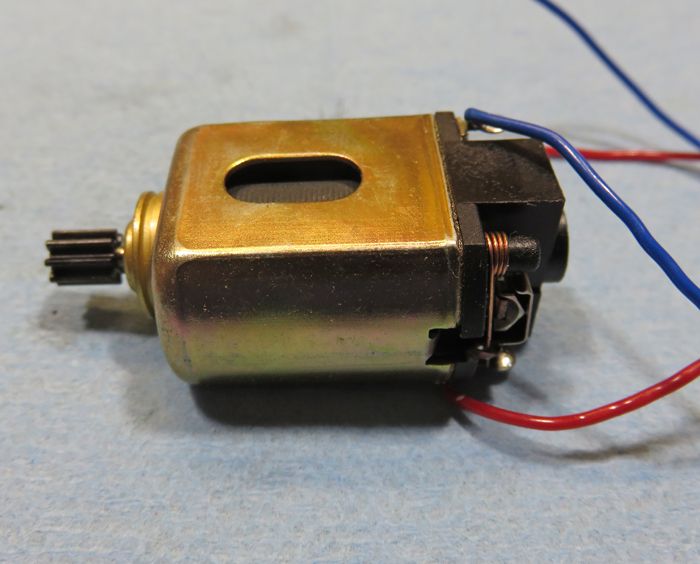
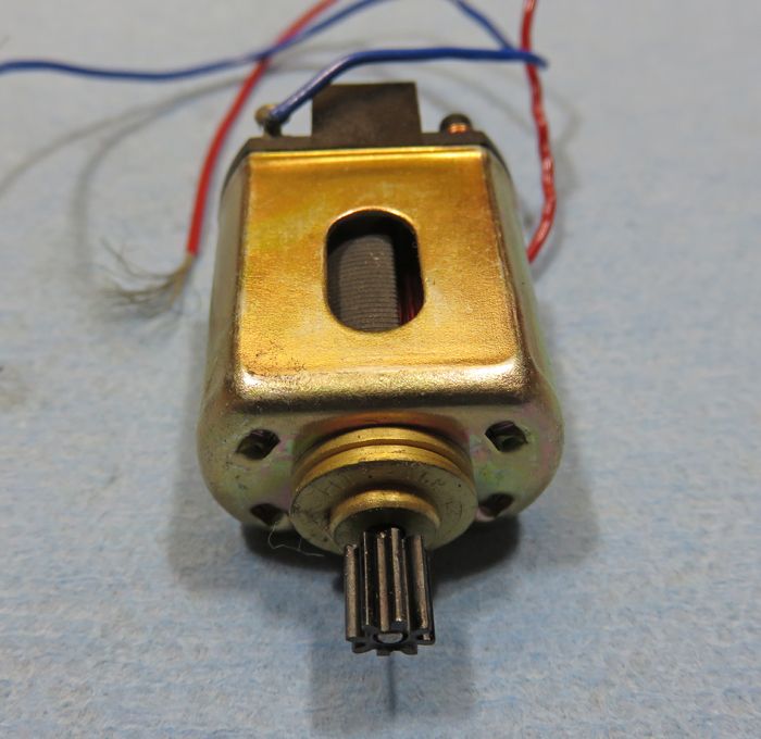
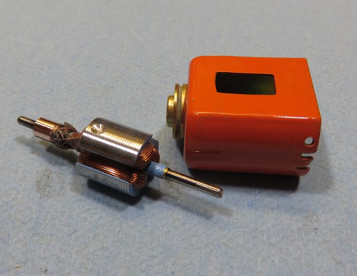
Aside from the color of the endbell, this version also has the larger bushing/bearing strap, similar to that on the Champion FT16D endbell. It also has oval can cut-outs. The can dimensions are interchangeable with the "regular" Japanese can where it matters and magnets and endbells are interchangeable. One other external difference is that this version comes with a pinion pressed on to the splined shaft, making me believe this *might* have been intended for slot cars, even though it's obviously of later production. A spin-up on the power supply reveals that this version has a wind much more suited for that application as well, with impressive (relatively) RPMs and torque. The white endbell version barely turns at 6v and is still pretty dead even at 12v. Both motors' endbells are molded out of a material that's far far more durable and heat-resistant than the Japanese Mabuchis or the Champion FT16Ds.
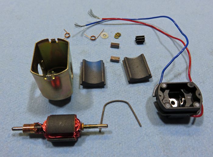
When you open the motor, there are further differences between this and the white endbell version. First off, the basic pieces are the same between both Hong Kong Mabuchis. The magnets on both versions are a solid step up from the Mabuchis, and work well with winds up to at least a #28. The commutators on both are (at least visually) the same as you'd find in a modern 16D like the Parmas and other Chinese motors, having induction-welded comm tab connections. These too are good for at least a #28, but I've had spotty success welding this type comm, so I would limit them to winds that can be silver-soldered.
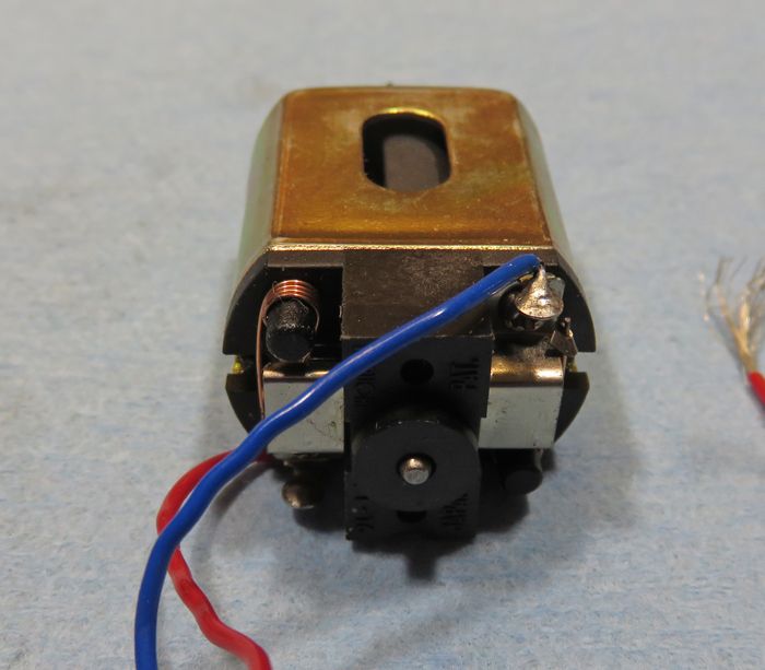
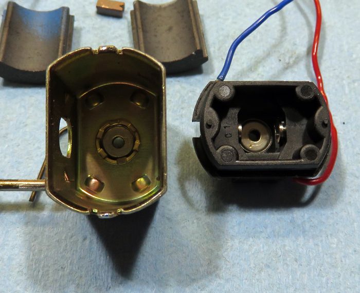
If you look at the inside of the endbell and the can, this version comes with ball bearings on both ends as opposed to the sintered metal bushings on the white version. While these "look" like the type of bearings found on some of the Japanese Mabuchis, they don't have that "maracas" sound those do, seeming smoother and more solid. That *could* however be the result of the stronger endbell and slightly thicker can metal. In any case, the bearings are a nice touch, even if they aren't nearly up to modern standards.
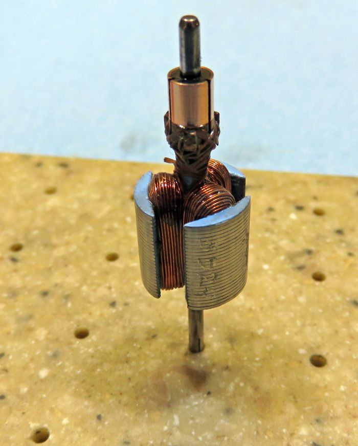
Back on the arm for a second, aside from the splined shaft, this arm has the familiar 70t/30 wind, as opposed to a bazillion turns of angel hair on the white endbell version.
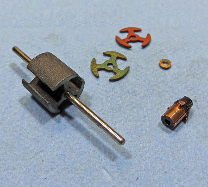
Time to start building. Taking the arm apart doesn't present any unusual obstacles. The thicker magnet wire is easier to unwind without it breaking here, although this version has some sort of lacquer/sealer on it, so you still have to be a little careful. The stack itself has the familiar "fiber end insulators" which will get tossed... I hate the things, and early rewinders often got rid of them too, so the feeling was sometimes mutual.

One small detail that's a welcome surprise on both versions of these motors is that the winding leg is a bit thinner on these lams. The original Mabuchi lams leg thickness was around .078", and on these newer ones, that's down a bit to .061" or so. That .017" may not sound like much to folks who don't wind these things, but it's a significant enough change to make winding these noticeably easier, even with powder coating.
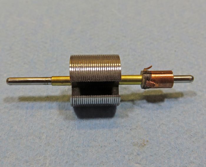
Speaking of powder coating, here's the arm ready for the powder coat. I pushed the stack a wee bit to put all the shaft "extra" on the drive end, because there isn't much extra on these in the first place. The shafts are of course "soft steel"... no drill blanks... duh... but they have been uniformly straight and round as far as I've seen so far after doing maybe twenty or so, and that's far more important. Before powder coating, I cleaned the outside of the stack and lightly polished the shaft. I also removed the extra phenolic from the bottom of the com so I could cut com and tail spacers out of 2mm ID tubing. That will give me maximum room for winding at the top and bottom of the stack. Because the comm will get tied and epoxied, it won't be at all weakened by doing this, and I believe that extra phenolic at the bottom of the comm is probably more about making building the stacks easy since no spacer is needed on the stock arm. After removing the fiber end-insulators, you're left with a very-"normal" .460" long stack.
... more to come.
-john


 ) . Just a great sounding motor.