


I'm almost absolutely certain there weren't any upgrade magnets available for "the homeset motor" back then, but there wasn't much good stuff period... at least off the shelf.
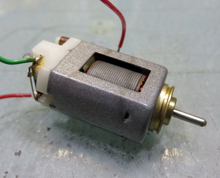
Well, decades later and I'm STILL tinkering with the little guys, and there are lots of options for making one into a wolf in sheep's clothing. First step is always taking them apart. Here, you have to deal with the splined shaft, and if you just pull the arm, you'll also be pulling out the "all-but-impossible-to-reinstall" can bushing. You can either slip something in to keep force on the bushing as you pull the arm or just cut off the shaft. I choose the latter most often because I figure those steel splines aren't doing the bushing any favors on the way out. That means... new shaft time:
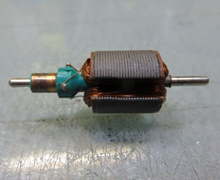
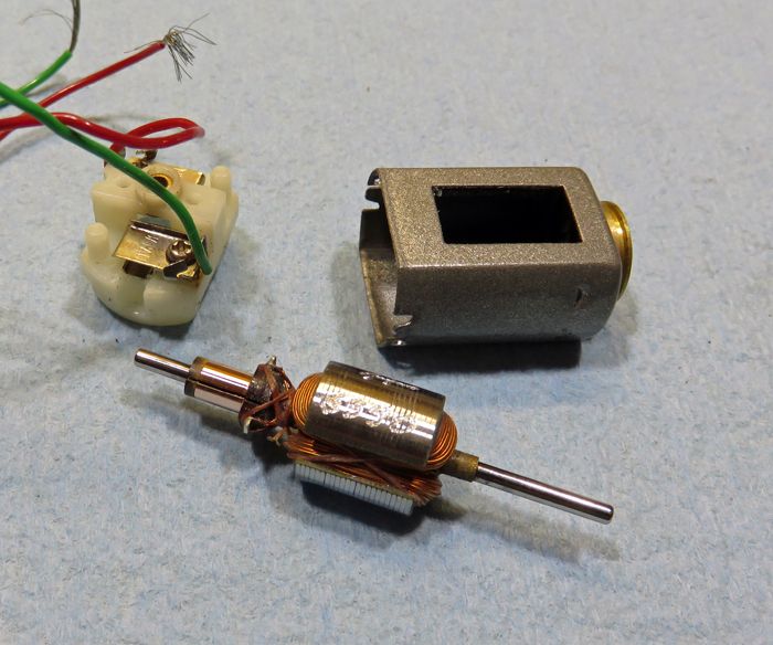
Once out, the arm is exactly the same as the 16D arm, but with an even milder wind. With the availability of better period commutators such as the Tradeship, the now-too-short shaft and far better ways to insulate the stack than the oversized fiber insulators, all I'll be keeping is the actual stack lams. On most all of the Mabuchi stacks, pressing out the old shaft with a new one will leave the lams loose and flopping everywhere, so you gotta be ready for that... but I have a plan. Also, if you DO keep the insulators and the steel tail spacer, beware of the sharp edges of that tail spacer causing shorts by damaging the magnet wire.
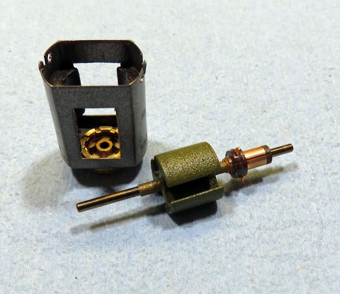
There's a lot going on in the above picture. First off, a set of polymer matrix neos from a burned up "Falcon" type motor were resized a bit to fit and epoxied into the can with a snug-fitting alignment slug. The stock "magnets"
 measure around 525-ish on my meter. These magnets measure a bit over 1230 installed and, if anything, are even lighter than the originals! Even though they're a bit tall before trimming, they are pretty much the precise length needed and can simply be slid to the magnet-stops when epoxying them in. You could grind a slight bevel at the tips and (after flattening the can tabs) just use two clips to install them, but I like to think it's "better" gluing them in.
Of course, the can got drilled for screw-retaining of the endbell because those tabs WILL fail either the second or third time you open up the motor.
With all those loose lams on the arm, I warm it up in the oven, lightly coat the inside of the lams assembly with epoxy, clamp it on all three poles and put it into the oven to speed cure the epoxy. Afterwards, you can often see a bit of the epoxy has migrated to the outside of the stack, penetrating right through the lams. You can't see it, but it has also gotten in towards the shaft so YOU HAVE TO MAKE SURE THE STACK IS WHERE YOU WANT IT BEFORE CURING!
After it's all cured, you clean all the excess epoxy and cut comm and tail spacers holding them in place with a tiny drop of super glue. While the Tradeship comm has a built-in phenolic spacer, I grind that pretty much off. The reason is that you want the same room top and bottom for winding, or keeping your coils symmetrical is a real bear.
These Tradeship comms have a built-in advance... in this case CW. Normally I'll defeat that by rotating the comm for a CCW advance. It puts the tabs in an awkward position for winding... not a big deal, but this motor will certainly be installed "inline", so all that need be done is flip the crown gear if necessary. Anyhow, the advance was OK, but I went a little past what the comm had... just because!
Lastly, the stack and both spacers got powder coated, here with a 3M material that's easy to use and produces good results. Ready for winding!
Now, with this motor and those neat magnets, a #30 wind makes for a potent package... a MIGHTY potent package. Afterwards, I tied it up "old school" because this wind on this stack is six layers, and those are always less stable than a more typical four-layer wind. After epoxying, balancing, and cutting the comm, it's "almost" time for final assembly, but there are a few mods to take care of on the end bell.
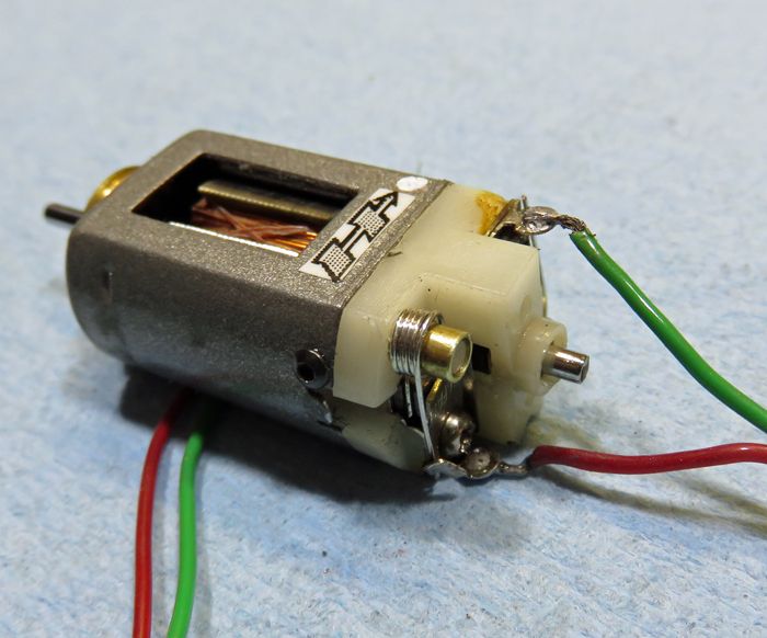
The above-pictured finished motor had to get the endbell drilled to match the can. Then, sleeveing the posts is a really good idea here, even with "only" a #30 wind. The sleeves were made from brass tubing, and the nearest size I could find needed to be drilled out for a VERY snug fit. I then wound a set of springs which in itself is a bit of a deal. These are a special type that need to be wound "backwards", and because of the height difference between the brush and the spring tab, I went "all the way" and made them five coils tall. Because of the springs, the sleeves and the fact that the stock upper brush hood is so close to the spring post... the hoods have to be clearanced enough to allow everything to work, but not so much that the brush isn't fully covered; easy does it!
The finished motor absolutely howls, having the kind of revs and torque that would put a mild period 16D rewind to shame. Sure it "could" go into a little Honda F1 (IF you're man enough to drive such a thing!
 ), but this motor could also go into a lot of FT16D 1/24 cars and they would benefit from both its power and it's much lighter weight. The deal here is the magnets!
-john


 Not exactly a high-tech solution, more like a Flintstones solution.


