Dragonslayer Seven
Here is a step by step for the new three-piece DS-7 from R-Geo. I have done an article on the DS-6 in standard stock frame rail format so Im going to do this one a little differently.
The standard build is five rails (.047") per side. Each side gets three main rails and a doubled up tripod rail. The new version could be built that way as well and probably most will want to do it that way. This one is two spaced main rails and one tripod rail per side so it will have more flex. There is also an easy way to add frame rails if you try this and it has too much bite.
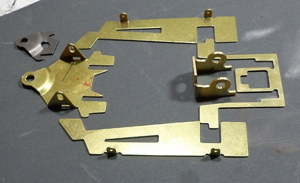
So... here are your parts out of the bag. These were nicely flat with only a bit of flattening to do in the bracket frame. This is a new bracket from Rick that is non-hypoid and has an angled bracket face.
As always, you want to sand or file the faces of the bracket so they are nice and flat, then youll square the bracket up if necessary. Then, you'll trial fit the bracket frame and may need to file a bit (arrows) so that it fits easily without binding. Then solder in place.


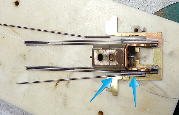
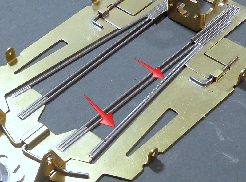
Next, we make up our frame rails into pre-fab sub assemblies. This allows for easier handling. You can see the two main rails with a spacer in the rear. There is also a piece soldered on the outside which takes the place of the inner tripod rail of the more standard build. You may need to file a bit at the arrow to make sure your sub assemblies fit without any bind.
Arrow shows where you may need to file for the sub assemblies. Forward of that, you can see that there is still a space left for the tripod rail to drop into.

Now, we make a rough bend in a stick of .047" wire in order to form our single tripod rail. After making the bend, we test fit the rail into the remaining space and file at the indicated (arrows) spots to make sure the rails will drop in with no binding. Its better to have a little too much space here than for it to be tight at all.
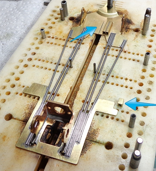
Now we go onto the jig and set our nosepiece in place. The slots for the front axle are a little oversized so we use a JK 3/32 solder-on retainer here so that the front axle is snug in the uprights. We want bushings and jig wheels at the rear so that front and rear axles are parallel. We have locating pins in place to help keep our main rail assemblies straight. Tack solder the main rail assemblies in place, then finish up the angled bends on the tripod rails, filing as necessary to make sure that the tripod rail fits easily with no bind. Notice a couple of little bits of .047" in place as spacers to hold the tripod rails out from the nosepiece a little. When this is all done, fully solder your rail assemblies and tripod rails in place.

Out of the jig for a minute. Clean the frame up so you can inspect all your solder joints. Then place the frame on your flat block and make sure that it sits flat. You may want to douse everything with acid and use a torch or hot iron on one corner at a time to see if anything settles a bit.

Back into the jig for a sec and make up your retainer tubes. The front is a pair of 3/32 square tubes at just over 3/8 long. They are soldered together and then cleaned and squared up. The rear is a bit of 3/32 inside of a pice of 1/8 square tube. The standard build uses the 1/8 with a 1/16 wire pin. I dont care for that much movement, so I use the 3/32 inside to fit more closely with a .047" pin.
Retainer tubes are now soldered in place front and side. Guide tongue reinforcer is also in place here. The GTR is shortened by about .100 in order to have more room for the front hinge pins Trial fit your pans as shown. I am using a longer wheelbase than the standard 4 and thus, I need to grind a little at the spots shown (arrows) in order for the pans to fit properly. The front and side pins are in place to show approximate placement.
NOTE: It was probably a strategic mistake to solder the front tube in place here. After I did it and started fitting the pins, I realized that it was a seriously fiddley process to work them into place to check the bends, then take them out and do it again etc. It is probably best to bend your pins and test fit as necessary, then put the assemblies in place and solder the tube in place.

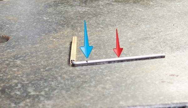
Here is a pic of the front pin on the flat block. You can see that the tube holds the pin slightly off of the block. If you install it this way, you will get a little pan droop when the pin drops flat to the nosepiece. You will want to make a tiny upward dogleg bend at the spot indicated (blue arrow) so that the pin sits flat on the nosepiece when resting in the tube. This is important because if you do this, you wont get pan droop. Then, youll make a rearward dogleg bend at roughly the spot indicated (red arrow) so that the pin rests fully on the tip of the pan.
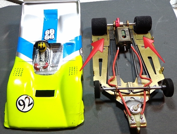
Here it is all wrapped up except for finish details. Ill be using body clips on this car so no pin tubes in place. Naturally tubes are more commonly used, but I like clips where practical. Bearings and front axle need to go in yet, but thats about it. There is a piece of .047" wire sitting below the finished frame. This is an extra frame rail that you can put in place if you feel that the car has too much bite. The second pic below shows it sitting in place as a second tripod rail. It could also be dropped into the space between the two main rails.

Ill show a final setup pic once I get it on track. Here is the new frame shown side by side with a stock build DS-6 that I just finished up for a customer. The frame rails on the DS-7 could well be set up this way as well.