Jump to content


Photo

"Unca Frank" Eubel's enduring legacy


  • This topic is locked This topic is locked
34 replies to this topic

#1 Cheater

Cheater

    Headmaster of the asylum

  • Root Admin
  • PipPipPipPipPipPipPipPip
  • 25,656 posts
  • Joined: 14-February 06
  • Gender:Male
  • Location:Norcross, GA

Posted 08 May 2015 - 06:33 AM

In the '60s slot drag racing was almost as popular as roadcourse racing, with seminal racers such as Gene Husting and Bob Braverman pushing their high-voltage bullets to ever-higher levels of performance. When the fad phase of the hobby passed, interest in slot car drag racing seemed to diminish significantly.


In later years, the drag racing part of the slot car hobby experienced increasing levels of participation, with notable racers like Bob Herrick and more recently Dennis "Foamy" Hill leading the way. Today, slot drag racing is one of the faster growing segments of the slot car hobby.


One of the most memorable characters in the world of slot car drag racing was the late Frank M. Eubel, who proudly used the nickname "Unca Frank." For many years Frank was heavily involved in SCCA racing in San Francisco and served at one point as the national Competition Board Chairman for that organization. The Eubels relocated to Virginia Beach, VA, in 1996, where Frank was a very active slot drag racer. He passed away from a heart attack in Dec 2004.


FE.jpg


Frank created a website to share his deep knowledge of the slot car drag racing hobby and titled it "Where Slot Car Drag Racing takes a brief Reality Break." IMO it contained some of the best dissertations on the nuances of this part of the hobby that have ever been written. His site was last updated on December 15, 2004, just a few days before Frank's untimely passing, and sadly there were many planned topics still under construction. Frank's website is no longer online, though it is occasionally available at an unreliable web archive site.


I'm going to bring the content of Unca Frank's site into Slotblog in this thread in honor of his memory and to preserve the insights and knowledge he wished to share, much of which is still as applicable today as it was more than a decade ago.


I was fortunate to be able to meet Unca Frank one time, on an impromptu visit to the former Fastrax Raceway in Richmond, VA. I wish I could somehow communicate the incredible quality of the cars, chassis, and motors in his box that day. I recall seeing a production C-can motor that he'd massaged and blueprinted to such an extent that it looked to have been CNC-routed from a solid block of steel and then polished. Without a doubt his stuff was as good as any slot cars I've ever seen.


The first thread will display a screenshot of Frank's website's homepage, showing all the slot car drag topics he'd planned to cover (I've omitted some material that's out of date or not related to slot car drag racing). The links shown in white have content which I will post in subsequent posts; the topics in black were "under construction" and never completed. Links in the posts may no longer be active and in some cases the formatting may differ from the original pages.


The following posts will be in the same order (well... mostly) as the links on Unca Frank's home page.


  • endbelldrive, Steve Boggs, and 2 others like this

Gregory Wells

Never forget that first place goes to the racer with the MOST laps, not the racer with the FASTEST lap


#2 Cheater

Cheater

    Headmaster of the asylum

  • Root Admin
  • PipPipPipPipPipPipPipPip
  • 25,656 posts
  • Joined: 14-February 06
  • Gender:Male
  • Location:Norcross, GA

Posted 08 May 2015 - 06:36 AM

Unca Frank's home page:


uf1.1.jpg

uf1.2.jpg

uf2.2.jpg


#3 Cheater

Cheater

    Headmaster of the asylum

  • Root Admin
  • PipPipPipPipPipPipPipPip
  • 25,656 posts
  • Joined: 14-February 06
  • Gender:Male
  • Location:Norcross, GA

Posted 08 May 2015 - 06:54 AM

An Introduction to Unc's Pages

 
Welcome to my... whatever you want to call it. Before you dive in, let me give you an explanation about what's supposed to be going on here, and how I'm trying to do it. That way, you might be able to decide for yourself whether it's worth your time. Fair enough?
 
First, it's supposed to look this way. You and I have both seen thousands of sites where graphics ruled and flash reigned. Most designers (web and other media, it would seem) love chaos, images, and free space, and fit content as simply as possible because it looks nice. I know, because I spent a long time hiring and working with them out there in the real world. I, on the other hand, am not a designer. I read things. In this site, you'll have to, as well.
 
Second, there aren't any objects that beep, flash, move, scroll, sing, play music, disappear, reappear, or do anything graphically or audibly entertaining. There aren't any real frames, either. It looks like a letter, a list or a magazine or newsletter, depending on how I felt at the time. It is also not an exhaustive or complete study, listing, or overview of anything.
 
Third, this site reflects my lifelong fascination with the interaction of people and the everyday mechanical and technological marvels that surround them, and their interaction with one another regarding those devices. Which means I like cars, planes, trains, and toys, as well as the people who mess with them. So this site generally is about those things and those people. If that interests you, the following pages might, as well.
 
Fourth, it really wouldn't hurt to have a fairly broad sense of humor, as well as a mite of tolerance for the periodic in-jokes and bits you might not relate to.
 
Last, when you come down to it, it's about what the Web really offers: the ultimate vanity press combined with the ego-driven cyberversion of the running of the bulls at Pamplona. I'm doing this because I want to, not because I have to. On the other hand, maybe I do. Either way, it's basically still me telling you about stuff I like. If I sound like the kind of person you'd strike up a conversation with, then this site will probably make sense to you.
 
Otherwise, it's your turn to decide - read or eject? Whichever, thanks for stopping by. Godspeed.


*     *     *     *     *     *     *     *     *    *     *    *     *     *     *     *     *     *     *     *     *


This site, such as it may be, is respectfully dedicated to the only other people I ever knew who wanted to know everything about everything: my late father and the late Dick Martin, who was, at the time of his passing, the Technical Manager of Club Racing for the Sports Car Club of America. They both taught me about the elegance of simplicity and good design, the wonders of the many commonplace mechanical things that surround us every day, and the value of friendship, sportsmanship, and a job well done. I miss both their presence and their counsel. May they rest in peace.


#4 Cheater

Cheater

    Headmaster of the asylum

  • Root Admin
  • PipPipPipPipPipPipPipPip
  • 25,656 posts
  • Joined: 14-February 06
  • Gender:Male
  • Location:Norcross, GA

Posted 08 May 2015 - 07:09 AM

Some Frequently Asked Questions About Slot Car Drag Racing


How much does it cost?

It depends on how much you want to spend and how fast you want to go (just like real racing). Cars for Bracket and Index racing can cost as little as $35 - $50, and are frequently available used. Class racing cars, as is the case with their full-sized kin, range from $100 on up. Sometimes, way up.


Do I have to build my own car?

Not if you don't want to. New and used cars are frequently available from your local track, or can be built for you, If you're familiar with soldering, filing, and simple metal-cutting tools, there are complete chassis kits which greatly simplify the chassis building process. Motors can be purchased assembled, both new and used, or can be built up from components if you prefer.


How much do motors cost?

Slot car drag motors range from $10-$12 up to $300. As with real drag motors, more modifications, torque, and RPM escalate the cost. Many people happily and successfully Bracket race motors they've purchased used for as little as $5.


What are the tracks like? How do they work?

The tracks are 1/25 scale versions of the real thing, either a scale 1/8th, 1000 foot, or 1/4 mile (for reference, a scale 1/4 mile track is standardized at 55 feet). The electronic timing systems found at most tracks can be easily programmed for a three-light Bracket "tree" or a two-light "Pro" or heads-up tree, and have large light displays for pre-staging and staging. A computer enters a random delay time before starting either light sequence.

Depending on the size and layout of the building or commercial space they are in, slot car drag strips may be free-standing or, most commonly, mounted along a wall of the building. They are usually approximately 18" wide, so they take up little space, and generally share space with other types of tracks.

The power for the car's electric motor is supplied by braid on either side of the slot, which is energized by a variable "controller" the driver utilizes. The cars can do burnouts, slow rollouts, or full-power passes (unlike some R/C cars, however, they cannot back up).


How fast do the cars go?

At a vast majority of tracks, speeds are recorded in real miles-per-hour by an electronic timing system, and are displayed, along with ET (elapsed time), reaction time, and 60-foot time, on a visual display board. Speeds range from 25-30 mph for slower Bracket cars to over 120 mph for open Class cars. In scale speed, that's about four times the speed of sound!


How quick are they?

Slower Bracket cars may run ETs between 2 and 3 seconds on a scale 1/4 mile, while the fastest cars are capable of making a pass in less than .440 of a second!


How do they slow down and stop from those speeds?

All the cars, no matter what their speed, use the same method. Immediately after crossing the finish line, there is an electrical gap in the track braid; power is functionally removed as the car passes over the gap. The car then passes into the track's "shutdown" area (guided by the slot but now unpowered), where it runs through a length of tire adhesion "glue." The friction from the tires in the glue slows and stops the car. While this system may sound somewhat odd if you've never seen it work, it successfully stops those 120-mph cars in less than 20 or so feet. Remember: these cars only weigh from 50 to 150 or so grams, so the physics involved isn't all that astounding.


Is it difficult for the beginner to get started?

Not at all! Just like real drag racing, it takes a little while to get used to the "christmas tree" starting light system. A little bit of practice will quickly get you going. It's simple enough that five and six-year-old kids can successfully compete in Bracket racing - and win! And if your kids can do it, you probably can as well.


What kind of cars can I race?

In Bracket racing, other that a few simple safety rules, just about anything goes. Body styles and motors are unrestricted. Index racing (racing against a given pre-set minimum ET) Classes have some body style restrictions in some indexes. Index and Class racing are run under a national set of rules published by the Scale Drag Racing Association (SDRA). Class racing is broken down by body style and motor type. If you always, for example, wanted to race a '66 Mustang, a Dodge Avenger Pro Stock, or a Pontiac Firebird fuel funny car, you can finally do it - in 1/25 scale and at a price almost anyone can afford.


Are there many different bodies available?

Almost too many to count! Many different manufacturers produce a huge selection of bodies, with somewhere between 400-600 different types available at any given time. Your local slot car track will probably have a selection of the more popular bodies available, and generally has catalogs that describe other bodies the track can order for you. Most are molded in a thin, clear, impact-resistant polycarbonate (frequently lexan) that must be painted from the inside, protecting the paint from handling, impact, and abrasion. Pre-painted bodies are available for those who don't wish to paint their own. There are also Classes for cars using various types and styles of plastic model kit bodies.


Where do I start?

Start at your local track. You can find a useful Track Locator at the Slotside website [this site is still online, but has been inactive for a very long time], or you may refer to your local Yellow Pages, generally in the "Slot Car" or "Hobby" sections. Find out if and when the track has scheduled drag races, and show up simply as a spectator. Watch what goes on, how it works, and ask questions if you have them. You might be surprised; slot car drag racers are generally a friendly lot and eager to make new converts, so someone might loan you a car to race right there!


Honest - Is it very difficult or frustrating for the beginner?

Honest? Less difficult or frustrating than almost any other hobby of its type. Cheaper by far and lots less complicated than R/C car racing, model boats, or airplanes. It permits you to enjoy the hobby by yourself, if you choose, just "playing" with the car or cars in your free time. If you choose to compete (which most of us do) it allows and encourages you to compete at a level you feel comfortable with. You can probably afford more than one car, and, in most circumstances, can enter more than one car in most Bracket, Index, or Class Races (local rules may vary, so check with your local track).


Compared to its road racing or oval track cousins, slot car drag racing is far less frustrating for the beginner. It is also far less abusive on the equipment, featuring far fewer crashes and destroyed cars. Yes, slot drag cars can and do crash for various reasons, but not nearly at the rate of their circuit kin. Many veteran slot car drag racers have cars they've raced for years, not days.


#5 Cheater

Cheater

    Headmaster of the asylum

  • Root Admin
  • PipPipPipPipPipPipPipPip
  • 25,656 posts
  • Joined: 14-February 06
  • Gender:Male
  • Location:Norcross, GA

Posted 08 May 2015 - 07:27 AM

Basic Guide to Slot Car Motors for Drag Racing


A Motor "Spotter's Guide"


16D/Super 16D Motors

16D and Super 16D motors are the basic "entry-level" motors for all slot racing (a Super 16D is basically a balanced version of a 16D). While initial costs are low, quality varies widely, and domestic replacement armatures are becoming increasingly popular. For drag racing purposes, power output ranges from very low to low. An extremely popular choice for Bracket and Index racing, several heads-up classes also utilize these motors.


16d.jpg

*     *     *     *     *     *     *     *     *    *     *    *     *     *     *     *     *     *     *     *     *

"C-Can" Motors

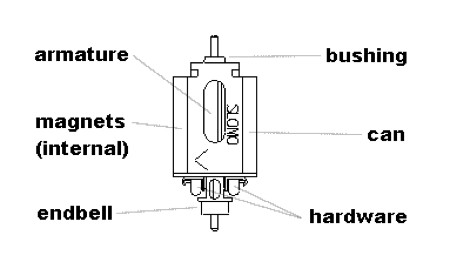
C-can motors are the most prevalent and popular in slot car drag racing. They range from Group 10 (using armatures such as Wasp, Hornet, Contender) to Group 12 and Group 20 (both using a different specified wire gauge and number of armature winds). While Bracket & Index racing permit any motors, a vast majority of Classes specify a G12 or G20 motor. All class racing G12s use bushings, while most (but not all) G20s use ball bearings.


ccan.jpg

*     *     *     *     *     *     *     *     *    *     *    *     *     *     *     *     *     *     *     *     *

"Cobalt" Motors


Cobalt motors, named after a primary component of their magnet material, are usually referred to as "Group 7" or "Open" motors if the armature is unrestricted, or "Group 27" motors if so specified. They commonly use a frame or "strap" for their support structure, and most frequently use ball bearings. Because of the powerful nature of cobalt magnets, G7 & G27 motors are extremely small and compact.


cobalt.jpg

*     *     *     *     *     *     *     *     *    *     *    *     *     *     *     *     *     *     *     *     *


Relative Motor Costs

[These figures are out of date]


16D & Super 16D:
Basic/Unmodified     $12 - $16

Competition/Modified     $22 - $50


C-Can:

Basic/Unmodified     $24 - $50

Competition/Modified     $60 - $150


Cobalt:

Basic/Unmodified     $120 - $160

Competition/Modified     $180 - $300
 

    For additional information on motor costs and availability, see your local track.


  • James Fetherolf likes this

#6 Cheater

Cheater

    Headmaster of the asylum

  • Root Admin
  • PipPipPipPipPipPipPipPip
  • 25,656 posts
  • Joined: 14-February 06
  • Gender:Male
  • Location:Norcross, GA

Posted 08 May 2015 - 08:00 AM

Some Popular Slot Car Drag Racing Classes


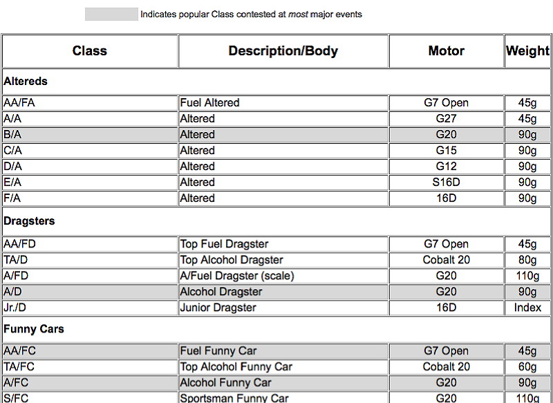
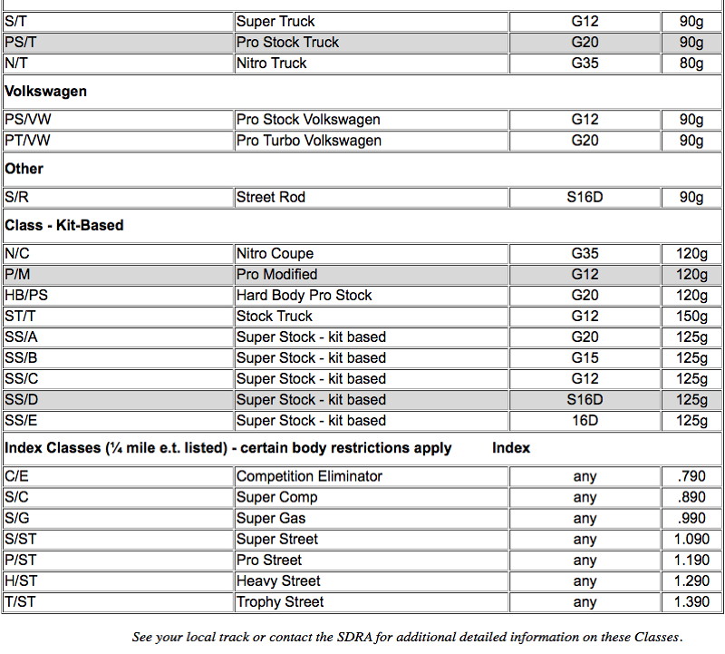
The national sanctioning body for slot car drag racing, the Scale Drag Racing Association, or SDRA [see note at bottom of post], currently lists almost 50 different classes of heads-up competition. Included are dragsters, funny cars, sedans, altereds, doorslammers, stockers, trucks, and even drag bikes! In addition, there are seven Index classes, which race against a predetermined ET, rather than heads-up.
 
While by no means a complete guide to the cars and their rules, the following chart may simplify how the classes are broken down by type of car and motor used. See the SDRA rules for more complete information on these classes, as well as race organization and conduct.
 

Comparison Chart of SDRA Drag Racing Classes


classes1.1.jpg

classes1.2.jpg

classes2.jpg


[Note: To the best of my knowledge, the SDRA is no longer in operation and I don't personally know if the infomation in this info is relevant to slot car drag racing as currently practiced.]


#7 Cheater

Cheater

    Headmaster of the asylum

  • Root Admin
  • PipPipPipPipPipPipPipPip
  • 25,656 posts
  • Joined: 14-February 06
  • Gender:Male
  • Location:Norcross, GA

Posted 08 May 2015 - 09:24 AM

A Glossary of Useful Words & Terms

A
airgap  – difference between the armature diameter and the ID of the magnets; total or per side


airgap tool  tool for sizing/checking airgap and/or installing/reinstalling bearings and bushings


align (brush hoods)  – to center the brush hoods in a symmetrical, 90° relationship with the centerline of the armature


altered – generic term applied to various coupe and roadster configurations run in specific "altered" classes


analyzer – common name for DC power supply used to break in and test motors


arc – visible electrical discharge; most commonly seen from motor brushes or car-to-track braid contact


armature – the three-pole device which carries the current-carrying windings and commutator around a central shaft


armature slug – steel or aluminum cylinder mounted on shaft; used in motor building


axle (rear) – the shaft that carries the driven gear and rear wheel/tire assemblies


axle, hollow – hollow steel or stainless steel rear axle


B
balance – achieving or possessing a state of rotational equilibrium; "in balance"


balance (verb) – to recondition the rotating mass of an armature via material removal


ballast – additional weight added to bring a car up to a specified competition minimum


batteries – commonly, the automotive, truck, or marine batteries that supply the track DC voltage


bearing, axle – commonly, the low-friction ball bearings permitted for the rear axle in some classes


bearing, motor – commonly, the low-friction ball bearings permitted in a motor for the armature in some classes


bracket – race grouping where cars compete using individual dial-ins via a handicap or delayed start


brackets (race) – commonly, refers to the entire grouping and competition of a bracket race


braid, guide – the copper braid pieces mounted in the guide which ride on the track braid and conduct current to the car


braid, track – the two strips of braid, commonly copper, on either side of the slot that convey power to the car


break – to incur a mechanical failure that prevents a car from starting or completing a run


break rule – provision in most rules to permit a 60-second pause for emergency car repair before starting a race


break-out – to run under (quicker than) a bracket or index dial-in


brush – carbon/copper/graphite parts that convey current to the armature's commutator


brush hood – endbell hardware component the brush rides in


brush tool, aligning – device for symmetrically aligning brush hoods to 0 degree offset from arm shaft center


brush tool, radiusing – device for cutting brush face radius to match commutator diameter


bushing, axle – oilite or bronze "button" or sleeve the axle turns in; serves as the "bearing" surface


bushing, motor – oilite or bronze "button" or sleeve the armature turns in; serves as the "bearing" surface


C
C-can – generically, name given to motors with specific, common can size; most commonly, Groups 10-20


can – stamped and formed steel housing that carries the magnets and to which the endbell is mounted


can end – the end of the motor where the gear is mounted and where the motor screws are inserted


can tool – tool for checking the size and reconditioning the shape of the motor can


ceramic (magnets) – generic term applied to all non-cobalt magnets; refers to nature of ("ferrite") metal oxide composition


charger (battery) – commonly, an automotive-type battery charger used to maintain, recharge, or boost track batteries


chassis – core structure or platform of the car, to which all other components are added or mounted


chassis, steel – chassis produced by chemical etching, laser or EDM cutting spring steel sheet


chassis, wire – chassis utilizing piano wire for major structural components


class (a) – generically, any individual competition grouping within a race or competition


class (b ) – commonly, reference to heads-up or specification-restricted race grouping


click box – commonly, a reference to the controller relay system that bypasses controller resistors and wiring


clip, lead wire – bent metal form interposed between car braid and guide to form an accessible lead wire soldering point


clips, magnet – wire or stamped metal retainers which mechanically maintain magnet position in a can


cobalt (motor) – generic term used to describe all motors utilizing "cobalt" magnets


cobalt (magnets) – commonly, generic reference to samarium-cobalt material used in high-performance motors


comm – commonly, shorter version of "commutator"


comm lathe (machine) – device for precision resurfacing and retruing copper contact surfaces of a commutator


commutator – polarity-switching, three-segmented, insulated copper device at one end of the armature; also: "comm"


controller – manually-actuated variable-resistor device used to regulate track power supplied to car


D
DBC – popular manufacturer of optical-sensor-based track timing system


diaplane – projecting front horizontal lip on a body; utilized for stability and airflow control


deslot – to come out of the slot during a run


dial – to select a specific ET, most commonly during a bracket race


dial-in – the specific e.ET selected, most commonly during a bracket race


donut – the rubber portion of (most commonly) the rear tires


doorslammer – generic term applied to coupes/sedans with "doors"


dragster – commonly, term used to describe dragsters or dragster-type cars


E
endbell – nylon, phenolic, or anodized aluminum fixture containing bushing and carrying motor brushes and hardware


endbell end – that end of the can/strap motor that retains the endbell


endgap – total amount of arm shaft freeplay between the inner dimensions of bushings and spacer ends of arm


endplay – total amount of arm shaft freeplay between the inner dimensions of bushings and spacer ends of arm


epoxy – single or multi-component adhesive used to bond wires to armature stacks, magnets to cans/straps


epoxy (verb) – commonly, the act of gluing magnets into cans or straps using various high-strength adhesives


ET – elapsed time, the amount if time from the start or the run to the finsh line.


F
flex – commonly, the beam-deflection or bending nature of a specific chassis


float – commonly, the amount of free play a mounted body is permitted by its attachment method


flux – commonly, the liquid or paste metal prep solution used to facilitate complete and proper soldering


flux (verb) – the act of applying a flux in preparation for soldering


flux, magnetic – a quantity expressing the strength of a magnetic field in a given area


funny car – generic term applied to highly-modified fuel coupes or replicas of current full-size cars


G
gauss, magnet (a) – the scientific unit of measurement of magnetic induction field


gauss, magnet (b ) – commonly, term used to refer to generic  or perceived magnetic field "strength"


gauss (verb) – also commonly, term used to refer to the act of measuring magnetic field strength


gauss meter – electronic or electro-mechanical device used to measure internal or external magnetic field strength


gear, pinion – the smaller driving gear soldered or pressed on the armature shaft at the can end of the motor


gear, spur – the larger driven gear that set-screws to the axle


glue – most commonly, the friction-coefficient improving semi-fluid applied to track/ties to enhance traction


glue – commonly, any adhesive used to secure one item or component to another


glue (verb a) – to prepare car and/or track via application of traction-enhancing "glue" (see above)


glue (verb b ) – to utilize an adhesive to retain an item or component


group – conventionally, the "category" of a motor, e.g. "Group 12" or "Group 27"


guide – the "shoe" that rides on the track braid and in the track slot; has threaded post for attachment


guide nut – nut that retains the guide to the chassis


guide tongue – chassis projection to and through which the guide is mounted


H
handling – generic term for how the car "behaves" and the way in which it makes its runs


hardshell – common nickname for model-kit based cars and classes


hardware – as a group, the metal or other components on the endbell which hold the springs, brushes, etc.


heads-up – race where both competitors leave the line at the same time; also refers to non-index/bracket classes


hone – generically, a device for precision-grinding a surface, usually round or radiused
 
hone, magnet – diamond abrasive-coated rotating device (see above) which precision grinds magnet ID bore
 
hone (verb) – to utilize a hone; most commonly refers to the act of magnet honing
 
hook up (a) – commonly, to attach a controller to track lane control terminals
 
hook up (b ) – also commonly, term used to describe presence (or absence) of traction
 
hub – the axle attachment point of a gear or wheel, through which the setscrew is tightened to the axle
 
hubs – commonly, term used to refer to rear wheel/tire assembly


I
index – the ET minimum against which a class is run; generically, used to refer to cars in those classes


L
lamination(s) – the multiple three-pole stampings which are assembled together to make the core or stacks of an armature
 
launch – commonly, the initial or starting portion of a drag strip run
 
launch (verb) – commonly, to perform only the starting segment of the run to observe performance
 
lead – material most commonly used for ballast
 
leadwire – the wire that conveys power from the guide to the motor
 
Lexan® – polycarbonate material most commonly used for quality slot car bodies; generally .007"-.020" thick
 
lift – the act of purposely slowing a car to avoid going faster than a set index or bracket dial-in
 
light – singularly, one of the timing system indicator bulbs
 
light (verb a) – to trigger or illuminate one or more starting sensor indicator lights
 
light (verb b )  to have a significantly better reaction time than an opponent, achieving a starting line advantage
 
lights – commonly, a reference to the complete starting light sequencing process


M
magnet(s) – commonly, the ceramic or cobalt magnets used for field generation in a motor
 
mask – adhesive material applied inside a clear body to prevent paint from covering an area, e.g., windows
 
mask (verb) – commonly, the act of using masks in preparation for body painting
 
match (magnets) – sorting and selecting, via gauss meter, etc., magnets possessing similar or identical field readings
 
mount, body – the chassis provisions or projections to which the body is actually attached
 
mount (verb) – commonly, to attach the body to the chassis


O
o-ring – generic industrial rubber or elastomeric rings used as front and wheelie-bar tires
 
open – generic reference to Open class or Group 7 motor


P
pan – flat chassis projection/area; frequently used to carry ballast
 

pass – common name for a drag strip run
 
pin – common straight pins, slightly bent, used to mount bodies
 
pin (verb) – to attach the body to the body mounts of the chassis via pins
 
pole, magnet – the positive/negative or north/south orientations of the field of a magnet
 
power supply – a variable DC voltage supply capable of running motors for break-in and testing
 
power supply, track – generically, term used to refer to the rating and amperage capacity of track power batteries 
 
pre-stage – to illuminate the first of the two normal starting line staging lights
 
push button – commonly, an on/off push button switch sometimes used in lieu of a controller to operate drag cars


Q
quads – two-segment magnets


R
rail – commonly, term used to describe dragsters or dragster-type cars
 
rail(s), chassis – the chassis components connecting the motor portion to the guide-mounting segment
 
ratio, gear – numerical ratio achieved by dividing the number of teeth on the spur gear by the number of the pinion
 
reaction time – time between the illuminating of the last countdown bulb and triggering of track power by the controller
 
red light – common indicator that shows a competitor has reacted faster than the specified start time interval
 
red light (verb) – to react quicker than the specified time interval after the last countdown light has been illuminated
 
relay, controller – device which, when activated at "full" position, bypasses all resistors and wiring in a controller
 
retainer – generically, any device used to locate or position a component, e.g. magnet, wheel, etc.
 
retainer (body) – small, flat-faced collars used at tubing ends to distribute loads and prevent body break-through
 
ride height – dimension between body and/or chassis and components and the track surface
 
rim – the thin cylindrical portion of a rear wheel to which the tire/"donut"  is glued/attached
 
rims – commonly, term used to refer to rear wheels
 
roadster – commonly, used to refer to any older, open drag car
 
roll, slow – the act of slowly driving the car down the track, usually for the purpose of applying glue
 
roll-out – calculated distance based on the circumference of the (rear) tire
 
roll-out (verb) – the act of slowly driving the car down the track, usually for the purpose of applying glue
 
run – commonly, term used to refer to a completed pass down the strip
 
run (verb) – also commonly, the act of making a pass down the strip


S
screw, endbell – screw(s) that attach the endbell to the motor can, usually four in number
 
screw, hardware – screw(s) that attach the hardware to the endbell, usually four in number
 
screw, motor – screw(s) that attach the motor to a mounting tab on the chassis, usually two in number

screw-in (motor) – a motor capable of being attached to a chassis via mounting screws and without solder
 
screw-in (chassis) – chassis constructed or modified to take a screw-in motor
 
sensor (track) – electronic (induction) or electro-optical (light beam) devices used to initiate and trigger a timing system
 
setscrew – small headless fastener with internal hex drive used to attach gears and wheels to the axle
 
setscrew, hollow – fastener (see above) with hex drive broached from end to end; slightly lighter weight than setscrews where the hex drive is not broached end to end.
 
scale – weighing device used to check class cars for specific class weight compliance
 
scale (verb) – the act of weighing cars, frequently during technical inspection
 
scale car – commonly, a car which has been built to maintain a more replica-like proportion and appearance
 
scale tire – commonly, larger rim and tire diameter which is proportionally more correct in appearance  
 
SDRA – Scale Drag Racing Association, national sanctioning body for slot car drag racing [in the past; now defunct]
 
shaft (armature) – the steel core shaft of an armature over which the stack laminations and commutator are pressed
 
shunt (verb) – to install shunt wires
 
shunt wire – additional bypass wires/braids from the hardware leadwire attachment points directly to the motor brushes
 
singles – magnets of one-piece or single-segment configuration
 
slot(s) – the actual recess which directs and restricts the travel of the car and into which the guide fits
 
slug (a) – commonly, name frequently applied to cylindrical airgap/bushing tool (see "airgap tool")
 
slug (b ) – shaft-mounted steel cylinder arm mass substitute placed in magnet bore when magnets are zapped
 
solder-in (motor) – a motor which must be soldered into a chassis to be mounted
 
solder-in (chassis) –
 a chassis into which a motor must be soldered to be mounted
 
spacer, armature – aluminum, brass, bronze, copper, or phenolic washers on armature shaft used to take up end play or float
 
spacer, axle – aluminum, bronze, phenolic, or plastic washers on the axle used to adjust clearances and wheel track
 
spacer, guide – steel, phenolic, aluminum, Delrin, or Teflon washers that adjust guide height relationship to chassis
 
spin – commonly, reference to tire "spin" during acceleration
 
spoiler (a) – properly, a front (by diversion) or rear (by trim or downforce) air control device
 
spoiler (b ) – commonly, used to refer to the rear trim/downforce air control device
 
spring(s) – the coiled tensioning device(s) which maintain(s) brush contact with the commutator
 
spring cup – cylindrical device, frequently aluminum or phenolic, around which spring is retained and pivots
 
stack – commonly, term used to describe the pole lamination(s) assembly of an armature
 
stage (verb) – the act of positioning a car at the starting line and properly triggering the staging lights
 
stage rule – during an event, the time limit imposed on an individual for preparing the car and track to race
 
staging light(s) – those lights which indicate that car has been properly positioned in the start line sensors
 
strap – light-weight, minimal, "U"-shaped motor housing; most commonly found in cobalt motors


T
t.q. – the top qualifier, car or driver, in a class
 
t.q. (verb) – the act of making the lowest ET qualifying run in a specific class
 
tab, hardware – the flat surface of the endbell metal hardware to which the leadwires are soldered
 
tab, motor – the plate or projection on a chassis to which a screw-in motor can be attached
 
tag – commonly, a reference to the identifying label required on the windings of most Group armatures
 
tech – that portion of a race during which cars are inspected for safety and conformance to class rules
 
tech (verb) – the act of inspecting a car to determine suitability for competition and rules compliance
 
thump – commonly,  reference to strength of the "cogging" effect of motor's magnetic field on armature
 
timing system – electronic/electro-optical system which calculates/displays reaction, ET, speed of a competition or run
 
tire (a) – commonly, reference to the rear tire/wheel assembly
 
tire (b ) – commonly, reference to the front o-ring used on the front wheels
 
tire truer – a special file or common emery board used to modify the shoulder or OD of tires
 
tire truer (machine) – motor-driven device used to cut, sand, or grind tire sidewalls and/or OD
 
track (a) – commonly, the racing surface or structure itself
 
track (b ) – also commonly, the store or slot car shop where the "track" is located
 
track © – the dimension between the centerline of the left and right front, rear, or wheelie bar wheel/tires
 
tree, Bracket – ".500" tree; three-light sequence, .500 of a second apart, used to start bracket and some other races
 
tree, Christmas – generically, reference to the entire timing system light assembly
 
tree, Pro – ".400" tree; two-light system, .400 of a second apart, used to start heads-up or index classes
 
tree (verb) – commonly, to gain a significant starting line advantage via significantly better reaction time
 
Trik Trax – popular manufacturer of induction-sensor-based track timing system
 
true (commutator) – comm reconditioning via turning, resurfacing, polishing, and cleaning
 
true (tire) – initial sizing or reconditioning of tire surfaces/OD via grinding/regrinding or cutting/recutting


U
upright – the vertical chassis segments which hold the bushings/bearings


V
voltage – commonly, reference to nominal available total voltage provided by track batteries/power supply


W
wind – commonly, term used to describe an armature by the number and gauge of wire "turns" it has
 
wind (verb) – reference to the custom or production manufacturing of armatures
 
wing (a) – properly, a separate, distinct (and usually detached) aerodynamic control and downforce device
 
wing (b ) – commonly, used to describe rear spoiler
 
wing © – term used by slot car road racers to generically describe any air-control device
 
wheel (a) – properly, the central (usually metal) component of a wheel/tire assembly
 
wheel (b ) – commonly, term used to describe the wheel/tire/"donut" assembly
 
wheel, wheelie bar – smaller-diameter wheels on wheelie bar assembly used to absorb launch shock and CoG transfer
 
wheelbase (a) – dimension from centerline, front axle, to centerline, rear axle
 
wheelbase (b ) – dimension from center, guide, to center, rear axle
 
wheelie bars – commonly, term used to refer to the entire chassis segment/axle/wheels/tires assembly


Z
zap (verb) – to recharge and/or reorient the magnetic field strength and/or polarity of magnets
 
 
Note: this Glossary originally started out with about 12 to 15 words, to which I added the words, terms, and phrases I could recall using or encountering referring to slot car drag racing. It now has about 215 entries, and, at that, probably still isn't very complete. But you know one of Unc's favorite motos: "Anything worth doing is worth overdoing."


These entries weren't borrowed or lifted from anywhere; I made them up from memory as I went along. So if your definition and mine differ, send me yours. If it works better and fits in the one line available, I'll use it. Use the e-mail, below. Likewise with missing words and concepts.


Otherwise, they're all reasonably close to accurate. Some appear redundant because they are redundant. Others take more space than one thinks they should. Try describing the appearance, function, and location of a slot car armature's commutator in thirteen words some time.


#8 Cheater

Cheater

    Headmaster of the asylum

  • Root Admin
  • PipPipPipPipPipPipPipPip
  • 25,656 posts
  • Joined: 14-February 06
  • Gender:Male
  • Location:Norcross, GA

Posted 08 May 2015 - 10:08 AM

Tools & Supplies For Slot Car Motor Building


Note: what follows, as is normally the case here at Unc's, is long, and a combination of some experience, pragmatism, and opinion. I trust you can separate those elements, use the things that fit your needs, and ignore the rest. I also presume that someone you know will tell you that all they need to build a decent slot car motor is a claw hammer and blunt cold chisel. Good for them. These are the things I use. It's a free country - make up your own mind based on what you want to accomplish, what you have, can get, and/or can afford. 
 
What you end up using is usually determined by the manner in which you end up approaching motor building. If you're a shake-the-box sort of builder, you probably don't need all that many tools. As you approach the serious end of motor building and "blueprinting," however, on your way to the Holy Grail of perfection (functionally impossible), you'll likely need more than that hammer and chisel. Below are some options, divided into four basic sections:


– Immediately below is some Basic Equipment, a good place to start.
– There's a section on Good Things to Have when you get a little further into motor building.
– For the truly obsessive, there's a list of Exotic But Useful Tools & Equipment.
– Finally, for those frustrating moments, some Emergency Tools and Solutions that may help.


Also, to put it in semi-legalese, nothing below should be construed as being an endorsement or representation of any product, manufacturer, or its/their suitability for any specific function or purpose. Ain't America fun these days?
 
Basic Equipment


Brush, Artists, No. 0 (fine) – Having tried all manner of application methods, this is my tool of choice for applying liquid soldering flux to anything, particularly motor bits and pieces. Everything else applies more than you need (and what you need for a good solder joint or connection is a lot less that what most people use). Buy a few of the cheap, sleazy sort; you're probably going to burn them applying more flux to a hot joint at some point anyhow.
 
Calipers, Dial/Digital – I suppose that decent calipers might actually be as or more expensive that the motor you want to build. Here are some points to think about: 1) A good set of dial or digital calipers can be a lifetime investment. Although I have a couple of digital ones, I still have and use the dial calipers I got 30 years ago. 2) There's nothing meaningful on one of these motors that can be measured with a ruler, or even a decent machinist's scale. The difference, for example, between an armature that measures .5095" and one that measures .5100" is .0005" and a possible disqualification at tech. Rule of thumb: if there's a minimum/maximum specification for something, you'd better measure it before someone else does. 3) In a pinch, the relatively inexpensive nylon or phenolic calipers commonly available will work pretty well, provided they have an accuracy of .001". I defy you (and your trusty calculator) to convert 1/128 of an inch in a hurry. They're also useful for measuring tire diameters when you don't want to goo up a good set.
 
Disk, Cut-Off, Dremel™, Thin, with Mandrel –  I've used diamond wheels, the thicker Dremel variety, and larger-diameter, fiberglass-reinforced discs. The thin Dremels are absolutely the most useful for cutting. If you use these discs for grinding, you'll learn they have the side-load strength of a fresh potato chip. Maybe less. Be careful and wear eye protection.
 
Drill, #58 – After trying slightly larger (#56 & #57) and slightly smaller (#59) drills over the years, this is the one I use. If I bothered to figure out what the pitch of the endbell screws was, I could tell if this drills the recommended pilot hole. If you can, buy more than one; at some point, you're going to break one off in an endbell, and after you get through screaming and swearing, at least you'll have another one to start over with (see also: "Emergency Tools," below).
 
Drill, 1/16" – I use this size drill for two basic functions: 1) to slightly enlarge and clear the can-to-endbell screw holes in the can. This helps to prevent interference with the endbell screws (and reduces the risk of snapping screwheads off), and 2) to provide an accurate but (very) shallow pilot hole in the endbell (side flange), using the can itself as the drill guide. This permits the smaller (and more easily breakable) drill for the endbell screws to be more accurately centered in the can hole.
 
Epoxy – Single or plural-component, a true epoxy is far superior to any easily-available "superglues" for retaining magnets in cans. While superglues have admirable tensile strength numbers, they have lousy impact resistance and shear strength in a metal-to-metal (or magnet) application. As I dispense with magnet clips and springs, this means superglues are out. For C-can use, the best single-component, relatively low temperature cure epoxy I ever used was a 3M formulation repackaged by (among others) Trik Trax. Currently unavailable (at least I haven't been able to get any lately), it cured at appxroximately 225° F for an hour into an almost bulletproof bond. As a C-can substitute, these days I use good old, reliable dual-component JB Weld. It has the added advantage of being a very low-temperature-cure epoxy, which means it can - eventually - air cure (though exposing it to some heat, either by baking or the time-tested light bulb method, speeds up the process a great deal). JB Weld, as well as most other common epoxy substitutes, do have some high-temperature strength problems, however. 
 
In anticipation of these conditions (mostly out of paranoia about the cobalt motors I build), the best substitute is Koford single-component magnet epoxy. It requires a slightly higher-temperature cure for a bit more time, (e.g. 360º F for 1-1/2 hour), but follow the instructions and it works very well.
 
File, #2, 8"-10," various shapes – For removing metal (or wood or plastic) in a gradual, controllable manner, a good, sharp file is still your best bet. Useful for external can finishing, particularly cleaning up external spot welds that are offensive and evening the length of can-to-endbell mounting ears. Most hardware stores (and even most decent discount outlets) carry major brands like Nicholson and other manufacturers, so a good one is easy to find at a relatively low price. File handles, generic and reasonably inexpensive devices which actually screw on to the tang of the file (for those of you who always wondered what that end was designed for), are a matter of personal taste and threshold of pain. Heavy use of larger files can be rough on the palm of one's hand. I usually use file handles on larger files when working on parts bigger than those involved here, but this one's up to you. 
 
File, Jewelers/Needle, #2, "Half-Round" -–"Partial Oval" is actually a better description of the shape, because it's really not half of a round or circle. These can be purchased individually, and are almost always part of a "jewelers" file set. For what you can use them for in this hobby, a cheap, imported set works just fine. Just make sure before you buy any that a) they're not absolute pieces of crap, overtempered and brittle (frequently but not always discernable by an incredibly low price and a chalky oxide finish coating) and b ) that the half-round file has a cut pattern on both the rounded and the flat sides (far more utility than just the rounded side). Avoid anything finer than a #2 cut pattern (e.g., #4) unless you have need of a much finer surface finish (and a file that loads up much faster). 
 
With care and a little bit of occasional cleaning, you can use #2 jewelers files on plastic, resins, brass, most non-hardened stainless, and all mild steel alloys. Refrain from attacking tempered steels (including some stainless), as you'll probably dull the file before you remove any meaningful amount of material. As I've never encountered a C-can (or cobalt strap, for that matter) that was anything other than mild steel (note that this refers to temper, not to carbon or non-carbon alloy or property), this shouldn't be a problem in motor work. The half-round file is particularly useful for deburring can edges and modifying and deburring can bushing holes. 
 
Flux, Acid – I'll tell you the same thing everyone else tells you - buy Stay-Clean. Use less than you're tempted to, remembering that soldering flux is a surface treatment. You only need to clean and coat what you're going to solder, not flood or drown it. That interesting crackling sound you hear when you touch a hot iron to a fluxed joint is excess flux splattering everywhere, but mostly on those new/shiny/expensive bits nearby. A small brush (above) helps. I use the top of a white plastic cap from a soft drink bottle for my flux; it's easy to see the one drop at a time I use. Any larger quantity for most jobs is a waste, as the water component of the "muriatic acid" (the watered-down hydrochloric acid most liquid fluxes are based on) is merrily evaporating while you're fussing around with something else.
 
And if that hydrochloric acid part didn't get your attention, it should have. Acid fluxes are notoriously caustic and almost always corrosive to most ferrous metals. This may seem like overkill, but wear eye protection when soldering. I've had several occasions to look up at both my soldering iron and flux brush in mid-air (with my hands on the table) while thinking "This is going to get real ugly real fast." Use care and common sense regarding both yourself and the items you're soldering. Water helps a lot, and baking soda and water helps even more (as a neutralizer for mild acids). When appropriate, which is most of the time, a vigorous scrubbing with a stiff toothbrush, soap and hot water will usually suffice to clean most slot car projects. 
 
Knife, X-Acto™ (or equivalent), with #11 blades – I have always used the small-diameter handles, as I never liked the feel of the larger ones. The latest versions, with the anti-roll square and quick-release mechanism at the end opposite the part that will slice your finger open, are very good, and even come in various colors to match your cars/box/decor. I use the #11 blade (long, sharp point) for everything, and put them in different handles in various sequences until they're absolutely dead. New and sharpest blades start out cutting decal film or body mask film, then progress to Lexan cutting, endbell flash trimming and deburring, plastic carving, metal deburring, and end up trimming tire donuts and deburring trimmed wheels on the lathe. Don't lose the cap that comes with the new knives, or at some point you'll end up pulling a blade out of you finger while bleeding all over your box. 
 
Loctite™ #271 Stud & Bearing Mount – If I can trust this stuff to hold real cars together, I can trust it to hold bushings and bearing in endbells. Mostly. I pay attention the the endbell bearing/bushing, because I've had a few (two) bond failures over the years in certain endbells while using synthetic oils. Nothing that has prevented me from using Loctite, those endbells, or synthetic oil, however. If I knew what the formula was for some of the oils and the exact nature of the materials used in those endbells, I'd have a better idea. If you use Loctite, remember that it is an anaerobic compound which cures in the absence of air (basically, in the joint, not on or around it), so this is just one of those many circumstances where more is not better. Use a toothpick and the drop-on-the-bottlecap idea from Flux, above, and you'll still probably use too much. I simply have never used a superglue in this circumstance (although I would hesitate to trust it implicitly), so I can't recommend it. In my experience, single or plural component epoxies will work, but are a pain in this function because they never mix thin enough to suit my application methods, and I'm particularly nervous about contaminating (and ruining) ball bearings. Loctite is also invaluable when building cobalt motors that require a press-fit strap bearing.  
 
Oil, Break-In – At some point, ready or not, you're going to have to break the motor in. Either that, or stick it in a car and blast the living crap out of it at a critical moment in its young life. I vote for the former. Without making this a recommendation for any specific type or brand, let me pass on an observation. In full-sized motors, racing and otherwise, the break-in period, however brief it may turn out to be, is critical for establishing the pattern of mechanical relationships and wear. Experience and a lengthy discussion with the president and chief chemist of a synthetic racing lubricant company led me to stop using synthetics for initial dyno runs and/or break-in. What a good synthetic is best at, it turns out, is not precisely what's called for at this point in a motor's life. Later? Absolutely. I approach slot car motors the same way. While the relationship of the brush to the commutator is by far the most critical part of breaking-in of one of these motors, I pay a little attention to the bushings as well (and a little less to bearings, if fitted, as they're usually pretty lubricant-neutral about break-in). Some of the bushings I occasionally use do not retain oil like an oilite, and are subject to different wear rates and characteristics. For either type of bushing, I refrain from using any form of synthetic oil in them until I'm satisfied that preliminary wear patterns are acceptable. Then I clean everything out and it's on to synthetics and buzz city. Just something to think about when you reach for that bottle for the first time on a new motor.
 
Pin Vise, 0-1/16" – You're going to need something to hold those drills for small-hole drilling, and pin vise is what you need. Available from a large number of manufacturers from General to Starret, start with something decent that doesn't grind a hole in the palm of your hand while you're drilling with it (sounds easy to avoid until you actually use one). This is not an application where a motor tool can successfully be substituted - too much speed (and too much heat buildup), too much run-out in the collet, too much everything. Learn to use a pin vise and an even, steady, and moderate pressure. With a sharp drill, they work fine. Too much side-load or flex, however... and it's "Emergency Tools," below. 
 
Solder, "Silver" & Solder, Rosin-Core, Electrical – I currently use four different kinds of solder, and have, at some point in various hobbies, used as many as nine kinds on the same project. Some melted at a temperature below that of boiling water. Practically speaking, however, you really only need two: one for joining things and one for common electrical connections. The "joining things" part is pretty simple: a good, reasonably high-temp, solid core, silver-bearing solder, sometime expressed as "98-2" or the like, referring to its alloy content of tin, antimony, silver, lead, dog fur, whatever. My favorite general-purpose structural solder is Sta-Brite, that blindingly expensive stuff sometimes packaged with Stay-Clean flux. Way too expensive for normal use. Instead I use the easily-available, prepackaged small rolls available from several different suppliers through your track. It's more expensive than buying the bulk rolls of the same solder alloy from a hardware or industrial source, but I've come to prefer the smaller diameter of the prepackaged stuff. I simply find it easier to work with. If you're wondering why "joining" has anything to do with building slot car motors: I may be the last slot car drag racer on earth who goes to the trouble of soldering the side seams on his cans. Although I know a) it's probably unnecessary, and b ) it adds weight, I've measured enough can seam junctions (both mechanically and ultrasonically) to be nervous about the strength of that joint after I wipe out most of the internal and external spot weld while grinding and finishing the can. Yes, the endbell screws help hold it together. I figure they're busy enough trying to retain the proper position of the endbell without being asked to hold what is basically a spring waiting to happen. Like everything else, just a personal opinion.
 
As to electrical solders, I'm probably wrong on this, but I personally have never noted any functional or performance difference between major brands of electrical/electronic rosin-core solders. So I buy it at Radio Shack, the track, or wherever I happen to be when I remember I need some for inventory. Some other things to think about and/or remember about solder and soldering: first, try not to forget that solder was never intended to be a method of properly fastening mechanical joints. Although not generally a problem in motor building, it becomes so in other facets of the slot car hobby. We're pushing this stuff way beyond what it was designed for (sometimes into the range of what should actually be brazed together, not soldered), so try to use joint designs that take that inherent lack of mechanical strength into consideration. Second, the proper method of soldering is to heat the work and apply the solder to it. Uh huh. Last person I saw do that consistently was a plumber, and copper pipes make for lousy drag cars. Like flux (and a host of other things), more solder is not necessarily better on a proper joint design. For those times when "sweat-soldering" and/or a large amount of solder is called for, however, nothing works better than a small butane/propane mini-torch (see "Good Things to Have", below). 
 
Soldering Iron, 35-40 watt – You can't really get by with less, and you really don't need more than this rating (even for chassis building). Soldering guns always look like a neat idea (Wow! A zillion watt gun! It'll be great!), but don't really deliver the concentration of heat over the area necessary to be useful. I've tried four or five, and they're all in a drawer now. While various hardware and discount store brands look intriguing and match the wattage necessary, some go through tips at the rate of one a week during heavy building periods. It doesn't take many tips to equal the cost of the iron, so let your wallet and projected-use frequency be your guide here. 
 
In the absence of an honest-to-God industrial unit (at commensurately more cost), the trusty Weller (usually) available from your local track is a decent buy. Although it seems expensive when compared to the discount brands, my experience has been that the break-even point is about six months, at which point the Weller becomes less expensive to own. As the tips are easily replaceable, buy a spare original-style one (wide chisel, usable for most everything) at some point. If you're in a mood to splurge, try a small chisel tip for more delicate jobs and most electrical work. Before you plug the iron in for the first time (and presuming you have access to some), a small amount of anti-seize on the heating-element-to-tip threads makes the eventual replacement of the tip a lot easier. Follow the package instructions and never tighten the tip more than finger-tight.

Sponge – Yes, a wet rag will work for cleaning the tip of your soldering iron. So will a wet paper towel. But a sponge is a lot tidier, and also more useful for collecting excess solder. Providing it's moist-to-damp, I've never noted that one cellulose sponge was actually any better than another for this job, so I use the cheapest ones of the appropriate thickness I can find (usually, under the kitchen sink when my wife isn't looking) and cut them to the size I need. After you discover that the cord to your iron has a life of its own, you might investigate a sponge/iron holder. Following a few dogs, I found a heavy-duty iron and steel-spring unit in a craft store for less than $10. I know a buck is a buck, but this thing works, and is stout enough to outlive toxic waste.
 
Stone, Grinding, 3/16", Oval – The most useful rotary tool stone I have for work inside the can, such as grinding the internal spot welds flush with the surface (to allow the magnets both a more accurate position and a better bond with the can sides) and deburring the can screw holes and edges more rapidly (but less accurately) than with a file. Also extremely useful for roughing up the internal surfaces of the can to permit a better epoxy bond, and if you're so inclined, rapidly removing plating from those can surfaces you no longer wish to be plated (a long story for some other section). I don't recall what selection of grinding and cutting tools comes with most motor tools, but if this one doesn't, it's certainly worth buying.
 
Tool, Brush Alignment – If you only buy one specialized tool for building slot car motors to start your basic collection, it should probably be one of these. Ultimately, I think they're more useful for basic motor building than one specific size of armature blank or slug. Brush alignment tools are available from Koford and others in a plain steel version for a reasonable amount, and from Magnehone (and possibly others) in a diamond-coated, brush hood-honing variety. This tool can be used with an armature blank or .078" drill rod (and in a pinch, a straight piece of music wire of the appropriate size) to adjust and position the brush hoods along the centerline of and at right angles to the armature shaft, and thereby (theoretically) the commutator. If you're so inclined, this tool is essential if you want to accurately advance or retard the endbell in relation to the armature timing (and, it goes without saying, use or modify a can that will permit you to). These tools are also useful for diagnosing the dreaded "I did it all correctly, but the arm won't turn easily!" condition.
 
This sometimes occurs when you use production parts manufactured to production tolerances (and sometimes when you mess it up all by yourself). The can (save for billet cobalt units) is a stamped and formed part. A vast majority of the non-strap variety are spot-welded to prevent them from spreading, then plated. In a jig, a bushing is then press fit to the can. Poof - it's done, and now you own it. As a) it wasn't made as a perfectly-matched set with the endbell, b ) the bushing may or may not be centered in the can (or even in the hole it was inserted in), and c) a version of this bushing location problem could also have happened to the endbell, you sometimes end up with d) a condition where production tolerances don't allow the two bushings to align to one another. Your armature is, essentially, bound by one bushing or another - or both. In the event you ever wondered why some people who build motors take perfectly good new parts and drift the bushings out of them, you now have some idea.
 
In the absence of any other can resizing and aligning or bushing installation and alignment tools (see "Good Things to Have," below), using the brush tool with a blank or test shaft will give you a clue as to whether or not the shaft will move freely in the bushings. If it does, in the absence of the tool, you're only half way home. The blank/shaft must also move freely with the tool in place and all the hardware properly tightened. If it doesn't, that generally indicates that the endbell or hardware (or both) is cocking the tool in one plane or another, causing the shaft to bind on the tool, not the bushings. While not fatal (crap, most people think it's not even meaningful), it does mean, among other things, that your brushes are not aligned perpendicularly to the centerline of the shaft Fixing the problem, however, as well as intelligent use of the tool in setup "timing alignment" or zeroing, is part of the building/repairing process, and this section is already too long. So: buy a/the cheap one ($5 or $6) and either figure out yourself how to best use it, ask someone you trust how they use it, or wait for Unc to get around to finishing that section of this site (if I were you, I'd go for one of the first two).
 
Tool, Motorized, 1/8" Collet – Motor tools come in a variety of shapes and sizes, but all share several characteristics: they cost more than you think they should, they turn nine gajillion rpm, and they have have, basically, insufficient torque to accomplish some of the jobs you'd like them to do. Having said that, whatever their limitations, they're also indispensable. Your first choice is economic; how much you can spend pretty well dictates how much tool you get. If it were my money (which it has been, eight or ten times), and I was limited to one tool, I'd ignore the accessory package and neato carrying case nonsense and wait for a good Dremel multi-speed, AC-powered unit with a keyless chuck to go on sale at a price that didn't offend me (this includes Sears, as I believe their motor tools are still made by Dremel. At least the ones I bought there were). Multi-speed because some things need to turn faster or slower than other things (like wire wheels vs cut-off disks). AC because if you're only going to own one, it might as well be a unit with the most torque available. Keyless chuck because all the other types will eventually drive you nuts looking for the proper wrench.

If cost is a major consideration, then wait for Sears or or your trusty local discount retailer to put the small, two-speed rechargeable Dremel (or Dremel clone) on sale. At about half the price and two-thirds the utility of its larger brethren, it's a pretty good buy in its own right, and a great second tool (I own four of them). I actually prefer the smaller to the larger rechargeable, as it's easier to fit it and a selection of tools for it into nooks and crannies of the average slot box and the larger tool doesn't give a performance advantage commensurate with its price premium. Just remember that the small tool has only two speeds (not quite slow enough and not quite fast enough) and minimal torque, so it's not the optimum choice if your needs beyond motor building require something stouter. While we're on the topic of not very stout, let me add that while I may never have owned a motor tool driven by the output of an "analyzer" or DC power supply, I could never see the need to, either. I've seen a few of them in action. All the disadvantages of a rechargeable, and  you have to haul the power supply along with it even when there's an AC outlet sitting there next to your box. Not today, thanks.
 
One final point: before you zip off to some other store looking for a motor tool or some other tool you may need/desire, give your local track a shot at the business first. While one of Unc's cardinal rules is "A Buck is a Buck," the differences between spending $6.39 for something at Wal-Mart and $6.99 for it at your local track are simple: I can't race at Wal-Mart, and nice people though they may be, they don't give two elemental hoots about what I do with it or who I am. Hopefully, at your local track, you can and they do. Your local track might surprise you, as well. Sometimes a "I might as well make X bucks rather than zero bucks" philosophy can get you an extremely righteous price. Never hurts to try. 
 
Tweezers, Fine-Point –  I don't know about you, but my stubby little fingers, while fairly decent at manipulating very small objects, are lousy for simply picking them up. I own lots of different kinds, but find a very sharply pointed, low-magnetic, hardened stainless pair the most useful (someday I'm going to figure out how tweezers got to be a bound "pair" and chop sticks never did). It may be a matter of personal taste, but I've never much liked the manipulative problems I have with spring loaded or "clamping" tweezers. When I need a strong, small, precision clamping device, I use a stainless steel hemostat of the appropriate size, yet another thing decent hardware stores now offer (usually from India and Pakistan) at prices lots better than the lab supply stores. Plated steel will work almost as well, but, if my experience is any indication, you'll eventually encounter deplating at the tips of even the best of them from the temperature and acidity circumstances you frequently use them in.
 
Another option is to simply grind the tips to meet your personal needs. Start with an inexpensive pair with a grip that suits your preferences. Work the sides and outer shape gradually to avoid temperature buildup, and leave the inner surfaces alone. Make sure the tips are symmetrical and actually still meet when you're done. If you started with a cheap enough pair, the tips may not have met before you started, so gently bend them until they do. If you're not inclined to get into the tweezer manufacturing business, our old friends at X-Acto and General usually have a few decent ones in their racks at hobby shops and more intelligent hardware stores. Expect to pay about $10 for a good pair and about $6 for an "OK" pair. My personal tweezer test is whether or not they can easily pick up a .003" stainless armature spacer from a piece of glass; good ones can and bad ones can't. Besides arm spacers, tweezers are great for gently handling motor brushes, sorting, holding, and manipulating springs, holding smaller things while you solder them, threading shunt wires through holes, and a host of other tasks fingers weren't properly designed to do. In case you need another reason, having a good pair in the box also makes sliver removal much easier   
 
Wrench, Allen, .050" – Forget that stupid little "L"-shaped deal somewhere at the bottom of your box. Spring the "big" bucks and buy a useful one, preferably double-ended (and with easily-replaceable tips) to deal with motor attachment screws as well. If you have two different wrenches for the two sizes, you'll invariably pick up the wrong one every time, particularly if you keep them in a pocket while you're racing. Engrave your name on it - these wrenches have an annoying habit of migrating to other slot car boxes in search of companionship. Put a piece of brightly-colored shrinkwrap tubing over (or similarly bright tape around) the .050" end so you know which end is which instantly when that gear loosens up with 20 seconds left to stage. Periodically inspect the very end of the tip; the facets of the driving hex wear after a time, and can lead to stripped setscrews and/or a completely rounded tip. Dress the tip flat by gently (and I mean gently) using a grinding disk in your motor tool. Absolutely avoid heavy pressure and long grinding that would detemper the tip. And don't throw away that other little .050" wrench - you'll need it if/when you have to remove that end of the, you should excuse the expression, good wrench.


#9 Cheater

Cheater

    Headmaster of the asylum

  • Root Admin
  • PipPipPipPipPipPipPipPip
  • 25,656 posts
  • Joined: 14-February 06
  • Gender:Male
  • Location:Norcross, GA

Posted 08 May 2015 - 10:42 AM

More Tools For Slot Car Motor Building

Good Things to Have

Armature Blank, Finish Bore Size(s) – Also referred to as a "slug," this is the cylindrical aluminum (or steel, for some uses) shaft-mounted "spacer" used to either set or check magnet bore diameter (a discussion of how and when to use this tool for those purposes can be found in the "Steps" section). It can also be used in conjunction with the brush hood alignment tool for setting endbell hardware, and, as you'll note in that part of the "Emergency" section, is invaluable for most can bearing/bushing replacement jobs. Some notes: the point of this tool has to do with the precision of a) its true diameter, and b ) its concentricity to the shaft. If the diameter is not exactly the dimension you need it to be, and if the shaft is not precisely centered within the body of the blank, all the measurements and references you make from the shaft of the tool will be off to that same (or greater) degree of error. Since there are two basic ways to make one of these things, both of those dimensions can vary to some degree based on the way the manufacturer produces them. The worst (and, of course, easiest and cheapest) way is to turn the body to final diameter first, then drill a shaft hole for a press-fit. The better (and more expensive) way is to rough-turn the body close to final size, insert the shaft, then turn the final body diameter between centers for maximum accuracy in all planes of measurement. At $5-$7 a pop from most suppliers, which way do you think most of them (or, at least, the ones I've seen) do it? Uh-huh.

When I'm not in a truly masochistic mood, I buy them (supplied by Koford and others) oversize (e.g. .530") and turn them to the diameter I need. This allows me more than a few magic moments when I look at what the nominal size on the packaging says compared to what the micrometer and dial indicator on the actual piece are telling me. When I do feel masochistic, I make my own using drill rod and steel or aluminum rod stock. In slot car racing, I figure this may be second only to making your own tires in the time-spent/wasted vs. end-product department, but what the heck, like the saying goes, "anything worth doing is worth doing to excess," right?


Block, Sanding, 320 grit & 600 grit – These are actually some things you can make yourself in about three minutes. Take a piece of something like 1x2 wood (its actual finished dimension is not really important) and cut it into a few pieces about 6" long. If you feel like it (and have access to the tools), you can dress the ends at 90º to the sides and (relatively) flatten one or both large sides on a belt sander (tidy but not mandatory). Then simply stick a partial sheet of self-adhesive sandpaper of your choice of grits to one (or more) side and trim the edges as necessary. Remember that these are not absolutely flat surfaces, so never treat them as if they are. You'll quickly discover a number of uses for these things, like cleaning up surfaces and edges, finishing work on can ends, and delicate solder removal work around some fillets like the can bushing. They're cheap, renewable, and offer additional uses in the slot car building realm beyond motors. Try one and see.

Compass, Magnetic – The quickest and easiest way to check magnet polarity in or out of the can. Just make sure that you and the person who "zaps" your magnets are on the same page regarding what "positive/negative" and "north/south" poles mean (a longer discussion of polarity issues can be found in the "Steps" section). This may be the only tool on any of these lists that can actually be found in a box of Cracker-Jack.

Drill, Set, 1/16"-1/2" – This is close to a judgement call. There are a number of drill sizes that are actually useful in building slot car motors, but they sure as heck don't comprise anything close to a set. But, hey, the subtitle says "Good Things to Have," not "You'll Die Without Them," right? Resist the temptation to snag one of these fractional sets from your local Boat People Tool Store 'cause the price is right. Many times, the drills aren't. Not to say, mind you, that some people's definition of "high-speed steel" seems to mean 2 to 3 RPM. Drills, like most other tools, represent an investment that should be amortized over time and multiple uses. Some things that look like drills, it turns out, won't actually drill holes in some normal materials more than once or twice, if you consider mild steel and aluminum to be normal materials (I do). Buy a name brand set (or buy a holder and assemble a set bit by bit - quasi-intentional pun - as you can afford them, eventually more expensive but momentarily less painful) from a reputable source. If you know how (or can quickly learn) to identify what you're looking for, this is another good item for your garage sale shopping list. Make friends with someone who owns a good drill sharpener, and remember that you're not likely to be able to resharpen drills of about 1/8" or less. And how, you might ask, does one use big, dumb drills on a slot car motor? When you discover that a normal countersink is too big to fit in a C-can when you want to deburr and relieve the internal can end to fit a bushing fillet, you'll figure out why having a sharp 3/8" drill handy is not a bad idea. Or when you finally decide that you'd actually like to see the bushing on some endbells so that you can lubricate it, not the endbell.

Drill Motor, Cordless – Repeat this sentence 10 or 15 times: "I will not use my motor tool to hone magnets." Done yet? Liar. This tool doesn't have to be great; it just has to work. Most cordless drills (we can dispense with the proper terminology) will work quite well, provided a) the drill chuck is reasonably accurate (most are), b ) the drill has sufficient torque to easily accomplish the task of honing magnets at a reasonable speed (most do, and your motor tool doesn't), and c) the drill has a battery charge life that is long enough at this workload level to allow you to accomplish what you sometimes need to do (some, surprisingly, don't). Mid-level units from most any recognizable manufacturer (and some lower-level units from better manufacturers) will fit the bill. If you don't already own one that can be pressed into service, expect to pay about $55 to $75 for a decent drill with the specs you need. Added benefit: this is a pretty generic purchase that, like a lot of other tools on all these lists, has uses beyond the slot car world. Take that into consideration if you're buying one for the first time.

Dye/Fluid, Layout ("Machinists Blue") – The stuff that lets you know what's still there after you try to make it go away. Alternately, the stuff that lets you scribe lines you can actually see on shiny things. Alternately, blue or red arm "dye" (you didn't think that arm manufacturers developed their own line of paints, too, did you?). A form of thin, translucent lacquer, the most popular brands of which are Dykem and Precision Blue, you can buy a large can for $3 to $5 at larger hardware stores, which, for most slot car motor uses, should last 20 to 25 lifetimes (if it didn't occasionally turn to lacquer-based, useless sludge in the can after a few years). I have both, but use the blue arm-dye bottle more frequently because it takes up less space on the bench.

Glove(s), High-Temp, Kevlar – Skip the name brands on this one (NASCAR and NHRA teams have a budget that's generally a little higher that ours) and find a source for some generic Kevlar, non-slip gloves. Why? Because at some point in motor building, not to mention the rest of this hobby, you're going to have to handle objects that are actually hot enough to burn you. While they don't really make you impervious to pain (even Kevlar has temp limits), they certainly help. You should be able to find them, somewhere, for about $10-$12 a pair. Other types of gloves will work (as I'm sure you already know), but most have a tendency to be bigger, bulkier, and to transmit heat far more easily than the Kevlar variety.


Hammer, Bodyman's, Flat-Face – Sometimes you just have to beat on stuff (e.g. can straightening). You don't, however, have to beat very hard. While the weight is about right, the face of a tack hammer is too small. The same is true for a ball-peen hammer of the proper mass. A bodyman's' hammer with a 1 to 1-1/4" flat face works best for me on these jobs. Once you own one, you can ask a body guy what he uses the other end for.

Hone, Brush Face, Diamond – I prefer these tools to their plain-steel cousins simply because they work faster, last longer, and seem to load up less. If cost is a serious object, the steel versions made by Koford and others will do the job for you, given the above limitations. For extensive work, however, I think the diamond hones are more useful. I own them in three different diameters, none of which (of course) usually ever correctly matches the diameter of the commutator the brushes are going to be used on (that's probably one of the reasons God let us figure out what breaking-in a motor actually did). There is a school of motor-building thought that says "To hell with the honing - just put new ones in and let 'er rip!" There is also a school that suggests rehoning the old brushes ever time you touch the motor (and you probably already know about the school that mandates new, honed brushes every rebuild or disassembly). Beats me. Many far wiser than I have even more ways to approach this topic, so I just try to pay attention, experiment, and note what works (and, maybe, why). I suggest you do likewise, remembering that what you're looking for should offer better results than the method you're currently using, not simply a different way to end up with the same result.

Hone, Brush Hood, Diamond – This is the more expensive and useful version of the brush hood alignment tool discussed in Basic Tools. Since all brush hardware I'm familiar with is stamped and formed, the hardware has a tendency to vary somewhat in configuration. Additionally, not all hardware from all manufacturers measures the same when it comes to brush mounting. Measure the width and height of a selection of brushes (using that spiffy set of calipers you own), then measure the installed dimensions of the brush hood. What you'll find is that most appear, at best, "tight," while some, depending on the manufacturer, are absurdly loose (I don't know about you, but the idea of a brush loose enough in a hood to actually rattle around doesn't really appeal to me. But what do I know, right?). 

The hood hone allows you to clean up, smooth out, and deburr the inner surfaces of the hood that the brush actually rides on. Since the honing has to be done by hand without an accurate center reference, and since you're doing it to copper, brass (yuck), or plated aluminum (double yuck), this is another of those circumstances where more is absolutely not better. Take it easy with the pressure applied. These hones are generally coated on two contiguous sides (in an "L" relationship), so they have to be rotated 180º to cut the two other surfaces. Once the hoods have been aligned, cleaned up, and smoothed out, there isn't any need to remove more material. It may be silly, but I use what I call a "drop test." If a new, uncut brush can be inserted on one side and drop through both hoods and the endbell on its way out the other hood, it's smooth enough for me.  

Hone, Brush Shunt Relief, Diamond – If you get tired of trying to use the flattened edge of a broken grinding disk as a tool for cutting reliefs for shunt wires (or hate your finger tips sufficiently to try grinding the relief with a disk in your motor tool), try this little honey. Another of the diamond-coated tool family from our friends at Magnehone, this basically consists of a coated wire and a holder. A few passes and it's done. Or ruined. Brush material is reasonably soft, so a diamond tool cuts it quickly. Practice on some dead parts before you turn yourself loose on the good stuff. This will also allow you to figure out how wide and deep you need to cut the relief to properly capture and retain both the shunt wire you use and the spring end. An added benefit of the diamond tool is that it cuts a rounded groove, diminishing some of the possibilities of cracking off the ears of a cut brush by eliminating two possible stress fracture routes. If you absolutely have to have a square-cornered slot, you can put the stress risers back in by using the flat edge of that grinding disk.

Hone, Magnet, Sizing Diameter(s), Diamond – See Below.

Hone, Magnet, Finishing Diameter, Diamond – I've lumped these two (or more) tools together because I'm firmly convinced that magnet honing should be performed as a multi-step process; that is, gradually enlarging the magnet bore towards the desired finished size in small increments of material removal. Can you cut loose with one hone of the desired size and end up with (mostly) the bore you want? Yes, and lots of people do. I did, too, until I thought about it. Installing the oversize magnets currently available in a C-can frequently gives you an internal magnet dimension as small as .460"-.465" (I have actually removed some material in some setups using a .460" hone as a "pilot" grinder). If your intended finished size is in the neighborhood of .520" or so for a C-can and the smallest internal measurement is, say, .470", you are about to ask that hone to remove .050" worth of material, or up to .025" per side, in one pass. In my opinion, that's a lot of work for a small-diameter, low to moderate-speed, diamond-coated tool with unknown bonding material to do. Not to mention the glue and/or knurl which retains it on the shaft or the time/temperature problem if you're not grinding in water. I use a sequence something like this: .460" or .470"/.480"/.490" or .495"/.500" or .505"/.510" or .515"/finish size. Wretched excess, perhaps, but no individual hone is overworked and each honing operation goes pretty quickly.

There's absolutely no doubt that magnet hones are some of the most expensive individual tools the average slot racing motor builder will think about buying. I counted, and I own 23 of the suckers, including a lot of custom sizes that made sense at some point, indicating that I should really have paid more attention to what I was buying (and that my life must be incredibly shallow to devote that much money to stupid crap like this). Before you spring the bucks, think about the following: while they may be priced similarly, not all hones are created equal. I look for those with a shaft length sufficient to be used from either side of the hone face, capable of full travel through the magnets, without the chuck of the drill hitting one end or the other. Not all hones are so constructed. Some actually have "handy" little hand knobs for "precision" honing. I'm sure many serious and/or "pro" motor builders enlarge the bores .001" at a time during experimentation, and use the knobs. Good for them. I have countless other ways to get blisters on my fingertips while boring myself witless, so I cut to the chase and use a drill at very low speed. As for cutting more than that amount by hand? I have some idea how long it took thousands of people to construct the great pyramids of Egypt, and I have no desire to be buried in a C-can anyhow. Another thing to consider is forming what, for lack of a better term, you might consider a "hone co-op," where a number of people each buy a different but utilitarian hone size, then trade back and forth when building motors. Worth a try.


A word about honing in water: I've come full circle on this deal, starting with water, going to "dry" honing, then eventually back to water. At the speeds and material-removal rates I deal with, heat was not a problem; even if it had become one, the temperatures generated didn't threaten my magnet epoxy bond, and I rezap all my motors after construction anyhow. Lubrication and ease of honing may be improved by doing the work in a coolant, but not to a degree that makes a dry method irrelevant. No, I went back to honing under water solely for magnet dust control. Honing in or under a fluid has a tendency to restrict the distance the ground magnet debris gets flung. Think about that a minute. 

Bushings are pretty forgiving of particle contamination, but ball bearings tend to commit ritual seppuku in the presence of particles. Hard particles. Hard magnetic particles. Well, it makes me nervous, anyhow. Nothing will actually stop some debris from migrating to your precious bearings, but the water has a tendency to restrict it to a worthwhile degree. I have found no useful difference between running water and a large pan or pot, and the latter is usually easier to accomplish in places people normally build slot car motors. By the way, you can resist the temptation to collect the sludge-like magnet residue and mix it with your magnet epoxy for some sort of magic fix. If your armature doesn't give a crap what the gauss reading on the outside of the can is, maybe you shouldn't either. I would caution you to develop an accurate touch or rotation sense about whether a bearing is clean and free of contamination. The easiest way to do this may be to take a new bearing, insert the shaft of an arm in it, and slowly turn it back and forth while applying a slight side load to the bearing. In a new bearing, you'll feel the increased drag from the side load, but shouldn't feel anything else. A little bit of experience here will go a long way. Make certain to completely clean the bearings in both the endbell and the can after each honing step before you proceed to the next one (or final cleaning and assembly). If you feel any imperfection or suspect that something is still in the bearing, keep cleaning it until what you felt is no longer present, and the bearing spins and feels like a new one. Some of the methods I use to clean motor bearings are in the "Steps" section, but this is one area where time and available equipment pretty much dictate your choices.

Lamp, Articulating, 60-75w – I've spent a vast majority of my life building models of one sort or another, and working with little bits and pieces. One of my many conclusions is that it may be impossible to have too much illumination on the subjects I'm working on. Too much glare, yes. Too much light? Probably not. And yes, I'm familiar with scientific studies that have calculated the proper number of lumens per square foot for most work activities. I've come to the understanding that no matter what my vision can actually resolve or focus on, it's the contrast between objects and their background that permits me to see it clearly. No matter how slight, sometimes it's the difference in shadow detail that helps your mind identify the thickness difference between a .003" and a .005" arm spacer lying flat on your bench or work table. I haven't found anything more cost-effective for decent illumination than a collection of inexpensive articulating "arm" lamps and normal incandescent bulbs (and I've tried all manner of diffused, indirect, and fluorescent types). Your needs may vary somewhat, but a few of these will suffice for most building activities. For what you want to use them for, the $10-or-so items at your local home center or larger hardware outlet are fine. Experiment with the bulb wattage, angles of illumination, and distance from work until you find what works best for you. As an added benefit, with a little thought and a bit of work, you can adapt their "universal" surface mounts to fit the edge or side of your slot box, allowing you to have some extra light at the track when you need it.


Notebook, Spiral-Bound, Small – Actually, get two of these, with different color covers. Keep one on your bench or building area, and use it to log everything you do to a motor while building it. Give each motor its own page to start with (front and back), and enter every significant component and dimension that makes that motor unique. As an example, topics could include: motor number/date built/endbell and bearing/bushing type/hardware type/can and can bearing/bushing type/magnet manufacturer/magnet final hone diameter/preliminary gauss readings/armature manufacturer, group, diameter, timing, meter readings if done, an so on. Don't forget to clearly identify the motor via some permanent number or marking on the can (most markings by "permanent" pens last until the second or third time you handle the motor - engrave your ID on them). Indicate the first application (car) the motor is used in, and its initial gearing. Thereafter, use that page to record rebuilds, modifications, arm substitutions, spring replacements, and any other significant change to the motor that in any way could alter its level of performance. What you're doing here is building the foundation for a - and may God forgive us - database of information.
 
You know all those internal trailer shots they use during TV coverage of major NHRA and NASCAR races, where the driver and/or crew chief are standing there, peering at computer screens? Those screens contain data, information, or, using the technical name, stuff. What they're trying to do is integrate what the car is telling them, via telemetry and performance, with what they already know. And what they already know is past performance, components, and configuration, expressed as entries in their database. No matter what your local computer gerbil may try to convince you, a database is simply the basic elements of (a) history, sorted out into bite-sized chunks. Done properly, it tells you what, where, when, and under what conditions something happened; it doesn't tell you why or how. Which is why those guys are staring at the screen. They're trying to come up with their best guess as to what to do fix/improve the performance of the car based on what they already know. You'll note that they don't rely exclusively on their collective memories here, and neither should you.

That other notebook, the one with the different color cover, is the one you keep in a back or apron pocket, ready to record all the rest of the information you collect during testing, tuning, and competition. It's the other part of your database or information history. Things like track temperature, gluing methods, spoiler angles, and the like (in addition to the usual ET, speed, and 60-foot times you may already keep track of). You want to know everything that has a measurable affect on how the car performs no matter what the motor does. It may be a major pain to do, but I look at it this way: given equal budgets and components, the person who knows more about the way his cars perform, and under what conditions, generally does better than someone who doesn't. Doesn't cost much either, other than time and effort. Your choice, though.  

Oven, Toaster – A kitchen oven is overkill and a waste of electricity. For curing and heating things that need to be cured and/or heated, a toaster oven is great. I have several, all purchased at garage sales, and the most expensive one cost $7. Why more than one? Sometimes you work on things in batches, and some of them may require a different time/temperature condition than others. Just one will suffice for most needs. Spend some time calibrating it with the oven thermometer (below) you're going to buy, because the normal toaster oven heat settings run along the lines of "sort of hot/hot/real hot/too hot." Also great for flaming those beef n' bean burrito snacks when you're too lazy to make it back to the kitchen. Toaster oven note: if the word "preheat" means nothing to you, ask your wife/significant other/mom what the recipe people mean when they use it, and apply the concept to your dealings with a toaster oven, particularly with higher-temperature work.

Pliers, Assorted (Needle-Nose, Small, Needle-Nose, Medium, Parallel-Jaw, Round-Nose) – There's a reason they make all those different styles of pliers. Honest. For holding, bending, twisting, and general forming, somewhere there's a pair of pliers to do exactly what you need to do. Before you go out and buy 30 pair, start with a few basics. Some good relatively small (4-5") and medium (6-7") needle-nose pliers will do 99% of what you need to do with slot car motors. As the strength of the pliers is roughly proportional to their size and construction, figure out what jobs require what strength before abusing a set into uselessness (hint: when you see the jaws moving before the piece you're trying to bend does, you probably need a heftier pair). Don't buy any with a nose small enough to puncture your skin; at some point, you probably will, either before or during the job that breaks one of the tips off. Unless you have a need for jewelers' pliers, a tip width of about 3/32-1/8" is normally small enough to do most everything you need on a slot car motor (and, for that matter, on a slot car).

 
When it comes to more specialized jobs, my favorite pair is a set of articulated parallel-jaw pliers. Slightly larger than a normal paper punch, these pliers apply reasonably even pressure along their jaws via an articulation linkage (hence, the parallel part), will bend or form anything connected to slot car work, have a grooved pass-through feature that allows long rod work to be run through the length of the pliers, and feature an external set of cutting faces for wire and rod work. I have a lot of cutters I've collected over the years, and these pliers work better for that function than any of them. Downside? They are not cheap. The ones I have were made in England and cost about $30-$35 some years ago, and I don't imagine that they (or ones of equivalent quality from some other source) are any cheaper now. For that other 1% of motor jobs, round-nose pliers (imagine a pair of needle-nose done as two long, tapering cones) work well for pre-forming wire and unwinding/rewinding/altering motor springs. Remember, however, that they are not as strong as the equivalent size of needle-nose pliers. For most of these purchases, I'd shop name-brand exclusively, with emphasis on a source that will be around for some time, and that won't forget what "lifetime warranty" means. Avoid the temptation to buy on the cheap; with these kinds of tools, you generally do get what you pay for. If you feel lucky, garage sales occasionally offer up some bargains. 

Power Supply, DC, Regulated, with Volt/Amp Meters – At some point in your motor-building career, the necessity of owning one or more of these will become apparent. What will not be so apparent, however, is which one to own. New ones? My opinion: if I can't blow up a cobalt open motor on it, it isn't worth owning. I don't care how neat it is, how small or (mostly) how big it is, how many dials, lights, meters, or controls it has. If one power supply cannot provide full voltage and sufficient amperage for every sort of motor I may work on, what's the point of having it? Granted, I rarely put a cobalt motor on the clips, turn the dial to Nuclear Meltdown, and flip the power switch on just to see how far the parts will fly. But I do like to run most motors in for a time in their final chassis installation position to seat in gear wear and the like. Some power supplies won't pull that load very well above about 2-4 amps, and I don't have a lot of motors that pull less than that, even with no load (except, of course, for the truly wonderful 16D family of fine pieces of... ahem, yes, those motors).

Used ones? I don't know of any good, cheap new ones. I don't even know of any bad, cheap new ones. So, should you come across one of those "I hate this stuff! Buy my box for X dollars" kind of situations, and the box contains a working power supply of a brand or type that someone on this continent has heard of, and it works, let your conscience and your wallet be your guide. At least in basic C-can building, some is better than none. Figure out what sort of overload and/or short protection it has; if it's fused, buy spares immediately. I once watched as my power supply repeatedly blew fuses when one of my very fast friends hooked up his AA/FC to it. Three tries, three fuses, but the motor showed no binds and measured with no shorts. So, scratching our heads, he ran the car. Fastest reverse pass I ever saw in my life, right back into a wall. Guess those little cobalt thingies really pull a lot of amps when you ask them to run 25º or so retarded.

Reamer, Chucking, .078" Nominal – Before you rush out and buy one of these for bushing work, you get to make some decisions: does the manufacturer of the arms you're messing with use a nominal 5/64" shaft (.078125") or a nominal 2 mm shaft (.078740"), and if so, how much do the shafts vary from arm to arm? While the basic difference (.000615") may not seem like a significant amount to you, it is to a bushing motor trying to turn a gajillion rpm. As the name implies, these reamers were designed to be chucked in a lathe to precision-size a hole (most commonly while the bit with the hole to be reamed is rotating in the lathe chuck while the tool is held stationary, but occasionally the other way around, as well). When used by hand in a pin vise, they a) make real machinists shudder, and b ) are nowhere near as accurate. Fine. Under most circumstances where you might press one into service (making bushing holes that are too small closer to the proper size), they're almost always more precise than a drill. Given the likely margin of error, I use a 5/64" reamer for most resizing jobs, and a .007800" (undersize) reamer with a dummy lapping-in shaft for jobs with a high paranoia level. Most likely functionally useless, but reassuring nonetheless. Skip the overkill part and stick with the 5/64" unit to start with. Straight-flute (recommended) or spiral-flute reamers this size should run between $6 and $8. 

Note: reamers, carbide tools, and other serious machine-shop bits you may have need of can sometimes be hard to find; snag an Enco Manufacturing or Rutland Tool & Supply catalog from one of your overtooled friends and get on their respective mailing lists for general and sale catalogs. Their prices aren't awful, either.

Reamer, Tapered, Utility – The quick and dirty way of making holes bigger. Nominally self-centering (yea, sure), tapered reamers make short work of enlarging can and endbell bushing/bearing holes. So short, in fact, that with very little work you can easily end up with a hole that nothing will fit in. "Judicious use" is the appropriate phrase here. The end product (hole) of a tapered reamer almost always requires finishing, no matter what material you're using it in (some degree of deburring will usually be necessary). Remember that while incredibly handy, one of these reamers is not truly a precision tool, and the size and location of your end result is strongly affected by pressure and angle. Also recall that the tool is tapered; the entrance side of the hole it creates is perceptibly larger than the exit side.

Scissors – Gee, you have to have a pair of decent scissors lying around that you can dedicate (or at least divert) to slot car motor work, don't you? Something that will cut and trim shunt wire, and not just bend it over the blade? A pair that can also be used to trim braid? Get some. Like this comes as a surprise: good scissors are not cheap, but scissors that will work for these purposes are where you find them. Don't expect a pair pressed into this service to a decent job on Lexan or other materials after a while. As for using side cutters: you'll note that other than a reference in the pliers section, cutters are absent from any of the motor lists. I have a lot of them, including a few truly weird pair, and none that I own will do anywhere near the neat and clean cutting job on this stuff that a decent pair of scissors will.

Scotchbrite, Coarse, Medium, & Fine – Some of the neatest stuff known to man, these industrial grades (grey, brown, and white or light tan in color) are cousins to the ubiquitous green scouring pads you probably have sitting on or near your kitchen sink. Available at reasonable prices at better hardware and auto parts/body stores, Scotchbrite will do almost everything medium-to-fine wet/dry sandpaper will do while lasting longer. The finest grade is outstanding for the final polishing of things that need to be, well, final-polished. I'm actually afraid to mention some of the things I use this stuff on, for fear you'll think I'm nuts. Suffice it to say that I use it - mostly the brown and white varieties - constantly. Try some and I think you'll see what I mean.


Screwdriver, Jewelers, Set – This is one circumstance where you probably can get by with something from our good friends at the Boat People Tool Store. Just don't expect too much (except a low price). Should you care to step up to the plate for a serious set or individual tool, small drivers manufactured by the West German company Wiha have handles that are actually usable, virtually indestructible blades, and a palm-pivot that works (which is to say, they don't bore a hole in your hand when you use them). You may find them in better hobby shops (I did), and while they're not outrageously expensive, they ain't cheap, either. One size, however, is absolutely perfect in width and thickness for those nasty little steel and aluminum 0-80 screws cobalt motor manufacturers love so dearly and motor builders hate so much. I'd think that a cheap set of generic jewelers drivers and one or two selected decent ones for specific purposes would do for most builders.

Scribe, Tungsten-Carbide/Diamond – For those times when you need to make permanent or semi-permanent marks on metal (or anything softer, for that matter), a tungsten-carbide or diamond-tipped scribing tool is a good first choice. Normal or "tool" steel scribers, while acceptable for plastics and acrylics (and wood, I might add, should you be using that material somewhere in your slot car building), wear too rapidly for my taste. A number of manufacturers, e.g., General, etc., provide them in pen-like holders, complete with the pocket clip (for the machinist's version of the Nerd Pack, I presume). Some come with magnets at the tip. Be my guest, but I cut the magnets off (see "Tool, Demagnetizing," below). Not very expensive, and useful for engraving top and bottom marks, polarity indications, brush indexing marks, and finished magnet bore size on a can. I hesitate to recommend an electric engraving pen, even though I have and use one, because after a gajillion years, I still haven't figured out how to make consistently-sized, neat and legible letters and numbers with the thing. Your talents, will, in all likelihood, exceed mine, so feel free to give one a try. What an electric pen won't do that a scribe will, however, is indicate neat, straight lines on a dykemed/blued surface for measurement or as a cutting/grinding-limit mark. If your funds (or interest) is limited, buy the scriber; if you're in a spending mood, buy both. 

The engraving pen will allow you to wile away the idle hours engraving your name and social security number on tools and everything else you own that isn't bolted down - and some stuff that is - as a theft deterrent. Don't blame me for the elimination of privacy, etc., involved with the name and SS number business; both the police and my insurance company asked me if all the tools in a massive box that was stolen from my truck had both on each tool. They didn't. Now they do.


Square, Machinist's, 4" – You don't need a great one (they cost about $80), but you sure can use a pretty good one (which, for our purposes, start at about $10). Like a lot of the tools on these lists, a machinist's square is used to make sure that something that's supposed to be a certain way actually is that way. In this case, that turns out to be things with an external 90º relationship with one another, such as the sides, bushing end, and endbell mounting tabs of a motor can or strap. Added benefits: the blades of a machinist's square are also extremely useful for providing a known flat surface for zeroing, advancing, or retarding endbell hardware (see the appropriate section of "Steps"), and a square is hard to beat for referencing the position of chassis bits against a known center line or establishing right angles on wheelie bar assemblies. Not, mind you, that this is a chassis section; just that at the end of the drill, you have to put the motor in something, right?


Tap, 0-80 Pitch – Sooner or later, you're going to need one (or more) of these when/if you work on certain brands of C-cans and just about any cobalt motors. They're small, fragile, and a pain to hold and position properly. Suck it up, because there's no way around them in most circumstances. A larger-capacity pin vice (see above) will make it easier, but nothing will make tapping holes this size fun. Remember that the proper hole diameter to start a 0-80 tap is 3/64" (.046875"), so stripped thread repair requires either some creativity or – groan – drilling and retapping to the next larger size (the most commonly available of which is 1-72, using a #53 pilot drill) that offers full thread engagement. When these break off in a work piece, you need to be a trifle lucky to salvage the part. While you can find them from some sources with a body size approximately the same diameter as the thread-cutting portion, taps this small are a little easier to hold and use (but also a little easier to break) when the thread-cutting portion is necked-down slightly from the body. General and others usually have them on their jobber racks. If you need one, don't forget to buy an appropriately-sized drill to go with it – a thoughtful combo occasionally available from your track, as well.

Thermometer, Oven, 0-600º F – The device that allows you to calibrate your toaster oven (or, when no one is looking, the kitchen oven) to more accurate settings. Maybe. I suspect that no one in the kitchen thermometer business worries very much about a +/- 5º F variance. I usually don't, either (although I do calibrate mine using a digital pyrometer found in the "Exotic..." section, probably a serious waste of time). If you use one that has a vertical mounting feature, you'll find it's a little easier to see through the small window of the toaster oven.   

Tool, Brush Radius ("Turtle") – One of Magnehone's brighter ideas, this hexagonal tool positions your brush in precise alignment with the centerline of a holder for Magnehone's (and, I suspect, others') brush hone(s). It has two alignment possibilities: one for "conventional" brushes, and one for "vertical" brushes. A few rotations of the hone (of whatever size you use) and the brush is radiused. Comes the debate: is this the way you should radius your brush faces? Depends. There is a valid argument for radiusing the brush faces in the assembled endbell while it is properly attached to the can, and while using the intended springs for the pressure source. I have, at various times, and for various reasons, done so. My opinion? Geeze, what a pain.

I'm so careless, I have to preload the brush hone with a spring to prevent inadvertently withdrawing the hone from between the brushes (this action is immediately followed by an interesting "Click!" noise, as the two brushes snap into one another and obliterate their respective faces). Yes, I could do one brush at a time on its respective side (which means that if I messed up with the hone, the brush would have to go all the way over to the opposing brush hardware to get ruined). Yes, I have to reclean all the parts to get rid of the brush dust. And yes, if I flapped my arms fast enough, I could probably fly, too. Well, sorry, but I buy airline tickets and use the Turtle unless the person I'm building a motor for demands otherwise. Additionally, I've never seen any performance difference between the two methods, and might, in a pinch, bet real green, rectangular dollars that there probably isn't anyone in the country who can tell me how and in what orientation method a bush was faced after a break-in on a power supply and a few passes down the track. This is a threshold-of-pain-in-the-butt purchase; if/when yours is exceeded, buy a Turtle.

Tool, Bushing/Bearing Installation & Alignment – If it were up to me, this would be the second or third motor-specific tool I'd buy (while purchased in conjunction with the can sizing tool, below). Provided it was reasonably accurate. How so? I own a bunch of these things, made by several different manufacturers. I had to buy more than one to get something that fell within an accuracy range I was comfortable with (+/- .002", and I'd like it to be less). Some were as much as .012" off center in one or more dimensions (the centerline of the shaft was measured at both ends on a surface plate with a digital height mike, then flipped over and measured again on the opposite surface; the same was done to both sides of the tool). Remember the business with armature blanks? I suspect some of these were made the same way. One, supposedly for a C-can, was big enough to actually turn down to the proper side radius and dimensions, then chuck up on a surface grinder to redo the flat surfaces to a correct plane and dimensions. If there was enough excess material to do that, it was either a S16 tool mispackaged, or a really bad job on a C-can tool.

Lacking exotic tools and a surface plate, how do you measure one? Use the thin blade portion of a dial or digital caliper, one end on the shaft and one end on the body of the tool in the dimension you're checking. Understand that what you measure will be greatly influenced by your ability to position the caliper blades at exactly the same spot along their length, and at exactly the same corresponding location in the other direction. Given the imprecision of this method, what you're looking for is gross misalignment, not perfection. A good bushing tool, with a tolerable level of error, is still much better than no tool at all. Why all the harping on precision here? Given that this tool provides the theoretical ability to insure that a) the centerline of the armature is in the true centerline of the can, b ) that the magnets are both equally-sized and disposed from that centerline, both before and after honing, c) that the endbell is positioned in a correct relationship with the can and that d) its bushing/bearing and hardware are similarly registered off that centerline, is there any question that an accurate tool is useful?

Tool, Can Sizing – These tools are invaluable for accurately (or grossly, for that matter) dimensioning the internal surfaces of C-cans by altering the external configuration (yes, they're also available for our old friends the 16D series, and no, I never found one that would work on more than one manufacturer's can dimensions - sometimes. Still looking, though). As discussed elsewhere in this section, cans (particularly C-cans) are stamped and formed products being asked to do fairly precise things. The very nature of the manufacturing process works against that being easily accomplished, so don't expect miracles. Once you get past whatever form the internal facet of the seam spot weld has taken (or after you've ground it flush), you may note that the primary distortion in the can tends to be either what you can't fix (the misalignment of the the can sides or endbell mounting tabs) or what you should fix (the distortion of the can bushing-mount surface). Since I knock the original bushings out of cans before I do anything else, I use this tool to reform that surface as close as possible to a 90º relationship with the top, bottom, and sides of the can. A machinist's square (above) will help a great deal here. The rest of the dimensioning is up to you and the exact size of the tool you end up with (like the cans, they vary from manufacturer to manufacturer - big surprise, huh?). Contrary to some methods of motor building, I've never bothered to beat the living daylights out of a can in an effort to make it oversized in some way; if built to pass SDRA tech, it takes a lot of time, looks like crap, has a measurable, detrimental effect on the internal gauss readings of the magnets if not done precisely and uniformly, and, given the maximum magnet thickness, minimum arm diameter, and desirable air gap in C-cans, offers no significant advantage over a conventionally-sized can built to the same Rules. Let your conscience be your guide.


Tool, Demagnetizing – Sooner or later, the ability of the motors you work on to magnetize tools will a) amaze and mystify you, followed shortly by b ) make you absolutely nuts. When used properly and frequently, a demagnetizing tool will help. They're available from a number of sources, and don't cost much when compared to a lessened frustration level. Follow the instructions on the packaging and experiment a little.


Tool, Timing, Armature – This is your admission ticket to the Great Timing Debate, in all its versions. Beyond simply determining whether an arm is high or low-timed (something, after some experience, you should be able to tell simply by looking at the relationship between the commutator and the arm stacks), a timing tool lets you ponder the mysteries of arm manufacturing. Most people who make armatures will tell you that the system and equipment they use makes it virtually impossible for them to mess up the timing of an arm, within a reasonably small margin of error. A good timing tool occasionally tells you that "reasonably small" may mean different things to different people. Consider: to be precisely spaced, no matter what their relationship or timing to the stacks of the arm, the slots in the commutator must be disposed 120º from one another to be considered accurate. Seem reasonable? Measure, say, ten arms with a decent timing tool, and see what you come up with.
I have a timing tool that was made in a moment of whimsy by the proverbial aerospace engineer, with cost (apparently) no object and accuracy paramount. It indicates timing from the center of the slot along its surface, and is accurate to 1/2º (it isn't a small tool, either). I occasionally use it to check the readings taken with an MEC tool, which is smaller, cheaper, and easier to use. It does however, unlike its big brother, take readings via a blade inserted in the end of the com slot, a method some manufacturers will tell you is horribly inaccurate. Being the ignorant dunce I am, I sometimes wonder how the end of a slot that is supposedly cut at precisely the centerline of the arm shaft and continuously perpendicular to it can be that much more inaccurate than the slot itself. But hey, they make 'em and I just buy 'em, so what do I know? The bottom line for me turns out to be predictability. Given Xº nominal timing and Yº timing "scatter" (highest to lowest reading), the arm will probably perform in "Z" ballpark, taking arm meter readings into account. I don't buy arms by the gross, and work with what I get, and I've yet to find a "perfect" arm. No matter. Despite what some people would like you to believe, building slot car drag racing motors ain't rocket science, and sometimes knowing that something is "in the ballpark" is good enough. At least it is for me.

Tools, Cutting & Grinding, Assorted – After you get your first, second, or third motor tool, and spend some time standing in front of the Dremel display case wondering what on earth all those things could conceivably be used for, you're going to be working on a motor (or other) project some day and think, "If only I had a little dealie that could..." Go back and look at the Dremel case. That little dealie is probably in there somewhere. Some words of caution, however. There is a significant difference between tools that grind and tools that cut metal. A grinding stone, disk, or wheel actually sacrifices part of its surface when applied to metals (generally, the harder the metal, the more it loses or wears), and the output from grinding work is usually a uniformly-sized powder or grit comprised of various percentages of whatever metal you're grinding and the carbide/binder/whatever material of the grinding tool (and, uh, yes, if you do it right, you can actually start a fire with the sparks and incandescent material flung off from what you're grinding on). Messy, irritating, a pain to clean up, but generally not much of a problem when you use proper eye protection. 

Cutting tools, however, work on the premise that a harder, sharper edge will cut a softer one (real rocket science, huh?). Most normal steel cutting work (and a great deal of stainless, as well) requires a carbide tool, while softer materials, e.g. plastic, nylon, phenolic, can be cut with a generic "tool steel." In all cases, the cutting "debris" output is an unbelievable number of tiny slivers of material. Having somewhat more mass than grinding debris, they travel further. Like everywhere. Pick the right steel and the right tool, and you can spend hours picking bits of steel out of your skin. This may sound like safety overkill, but as a person who already has a few rust rings on the surface of his eyes despite safety glasses, trust me when I tell you that owning and wearing one of the many full-coverage, flip-up face shields while cutting or grinding, even with motor tools, is not a bad idea at all.

Quite a long time ago, and based on our methods and actions in our race car shop, a mutual friend used to refer to me and my partner as "Captain Caution and His Trusty Sidekick, Sergeant Safety." Guess he was right, huh?

Torch, "Mini," Butane – When rapidly applying lots of heat to a subject is called for, as in those circumstances where two relatively large or thick flat pieces have to be soldered together, a small butane torch is most useful. "Small," by the way, means less output than the conventional propane variety you may already own. Butane is the gas commonly used in that type of cigarette lighter, and a vast majority of the mini-torches available are designed to be refilled by the small gas canisters sold for the lighters. Unless you feel like lighting it with some other flame, mini-torches using a piezo-electric igniter are best.

Volt/Ohmmeter, Digital – Sometimes you want to know if your power supply is lying to you, and sometimes you want to know precisely what the available track voltage is. Start with a decent but inexpensive one (available at our old pals Sears and Radio Shack). $14 - $20 should get you something useful that you won't feel suicidal about accidentally stepping on. Beyond that level, things get more expensive, more complicated, but not necessarily more utilitarian, until they reach the $300 - $400 level. Although I haven't spent a career looking, I've yet to see one at a price I can tolerate that would measure DC Amps at the level we deal with them, particularly surges during the launch of a car. When I do, I know it's going to cost approximately its weight in gold or some such. Until that point, the inexpensive Radio Shack units fit my needs pretty well.

Wheel, Wire, Small-Diameter High Speed – Great for basic cleaning, some deburring on softer materials, and primary polishing on endbell hardware. Also excellent for shearing infinitesimally small wires from the wheel and embedding them in your skin. Another eye-protection-is-a-must tool. I've tried all the cup and brush-shaped tools known to man, and have them all in my handy motor tool holder. I use the wheel almost exclusively. Pay attention to the size and condition of the wheel; as they wear, they have a tendency to rust after some period of inattention. They'll still work, after a fashion, but shed wires at an even greater rate. The Dremel wheels go for about $3, so replace them when they start to make you nervous.


#10 Cheater

Cheater

    Headmaster of the asylum

  • Root Admin
  • PipPipPipPipPipPipPipPip
  • 25,656 posts
  • Joined: 14-February 06
  • Gender:Male
  • Location:Norcross, GA

Posted 08 May 2015 - 11:04 AM

Even More Tools For Slot Car Motor Building


Note: remember one of the opening scenes from the movie "Animal House," where the camera pans over to, then up, a statue of Emil Faber, the "Pencil King?" Remember what the inscription on the base of the statue said? "Knowledge is Good." Remember that when you read some of the things on the following list. Sometimes, it's just good to know stuff. 

Exotic But Useful Tools & Equipment

Cleaner, Ultrasonic –I've owned various types and sizes of ultrasonic cleaners for quite some time, starting with my model railroad days. Like the name says, they clean things, even quite small, complicated things, very, very well. They've all been universally useful, and sometimes helpful for the oddest things. Given that I do not use a hydrocarbon-based solvent, they're pretty good at taking paint off things that don't easily respond to other methods. Note: I don't use hydrocarbon-based solvents because the nature of the molecular action of an ultrasonic cleaner, even with a cover on, tends to elevate the solvent temperature to what I consider an unhealthy level. Unhealthy as in vapor/aerosol production/ignition source/big, ugly boom/fire/destruction. While my current cleaner does, not all such units have automatic temperature sensors that turn the cleaner off and on below a safe fluid temp limit. Frequently disposing of contaminated or dirty water-based cleaning fluid is also considerably less expensive than the same schedule with more aggressive solvents, not to mention environmentally friendlier. I don't know where to get good, inexpensive new ones (I doubt they exist), but I do know that as older graphics operations finally get rid of all their pen-and-ink supplies, they sometimes dump perfectly good ultrasonic pen cleaners. I picked up a 6" wide by 4" deep cylindrical Staedler-Mars (the Rapidograph pen folks) unit with a useful basket and temp-control for $10 from a drafting shop that way. I also have one that will take several complete AA/FCs at a time, but I paid retail for that hummer, and it's such a (size) pain that I never use it.


A word of caution regarding ultrasonic cleaners and some of their nasty habits: the types of cleaners we can afford to buy aren't smart enough to turn themselves off when something has been satisfactorily cleaned. They keep going. Some materials, e.g. copper, think this is a signal to start dispersing some of their surface molecules. So? So you put a bunch of copper endbell hardware parts in an ultrasonic cleaner, turn it on, and forget about it for some lengthy period of time. When you do remember, you pull them out to discover you now own the cleanest-looking corroded copper parts you've ever seen, with surface pitting everywhere. Or, for example, you leave an arm in the cleaner a bit too long, only to discover that some of the copper from the comm has somehow managed to "plate" the formerly clean and highly-polished stacks of the arm. Do I understand the physics? No. Do I understand the moral of the stories? Yes. Pay attention to the time it takes to completely clean something, and take the parts out of the cleaner at that point. Not, mind you, that any of this stuff has actually happened to someone like, uh, me or anything.

Checker, Wall-thickness, Ultrasonic – Overkill technology transferred from the real-car shop to the slot car shop (with a stop along the way at the manufacturer for recalibration). This is one of those deals where curiosity overcame common sense. Since I already had the tester (purchased for accurately checking cylinder walls on very lightly supported dry-sleeve race motors) and wasn't using it much, I called the manufacturer to inquire if its accuracy could be enhanced (about ± .005" between .050" and .400") if its measurement range was severely reduced. And should that turn out to be homemade dogshit, if they could convert it back again. Yes and yes. So now I have this really spiffy device that will resolve to .0005" at steel or iron thicknesses between .025" and .050". Yea, like I really run into a lot of .030" cast iron these days. It does, however, do a very nice job of measuring can material thickness consistency after forming. And hey, it only cost, what, 14 or 15 times more than a good digital mike with the proper ends that can do the same job and resolve to .00005". Someday, this tool is going to prove invaluable. For something. Important. Someday. 

Drill, Set, #1 - #60 – Only in slot cars would a numbered drill set be considered exotic. Go figure. Perhaps the best way to acquire a set is to think of them as trading cards: first, buy a holder, then collect your favorites, filling in the blanks as you go along. If you keep them long enough, some will become very valuable. Start with, say a #40 and work your way down to #60 before you work your way up to #1. Why? There are more small holes on a slot car motor than there are large ones. OK, that's a pretty lame reason to spend money, I'll grant you. It's just that I never tried to explain to anyone why owning certain drills was a good idea. Where's Tim Allen when you really need him?

Gauge, Bore, Digital, .0001 Resolution – Yet another of the things I bought for automobile use that has some utility in the slot car world. More properly referred to as a "hole" gauge, I originally used it to measure relocated .5625" lifter bores in one series of engines I worked on. As luck would have it, the range of .5000" to .6500" makes it perfect for C-can magnet work (and useless for cobalt motors - so it goes). What it allowed me to do was determine how round the supposedly "round" holes I was honing in magnets actually were, and, sometimes, why. I discovered, for example, that a certain type of can actually distorts a bit at its center during an aggressive honing "attack," and that the distortion leaves the center of the magnets ever so slightly smaller than either end. No big deal, other than it explains why some hones would sometimes "grab" in the middle of a cleanup pass after the initial hone. A few more passes with the same hone generally takes care of it. It's also useful for checking a finished hone pass (within its measurement limits, at any rate) against the nominal hone size. 

Indicator, Digital, .500" Travel, .00005" Resolution – The tool I use to amuse myself regarding how truly round or cylindrical things are. Another of the wowie-zowie (but useful) measuring devices from the folks at Mitutoyo. Originally purchased for crank and camshaft work, it's actually more useful for me on slot car motors than it was on automobile engines. As the King of Paranoia, I used this to measure run-out and other meaningful things before I sent work out (to be fixed or changed) to a machine shop I trusted implicitly. Then I'd measure the work again when it came back to make sure they did it right. See what I mean about paranoia? Nowadays, though I still can't grind cranks or alter cam profiles at home, I can measure armature stacks and commutators for "roundness," and, in most circumstances, can do something about them. Wait a minute, you're saying to yourself, what's this crap about stacks not being round? Of course, they're round, uh, aren't they? Yes, pretty much, but sometimes they're not necessarily as concentric to the shaft as you might want them to be. The whole arm manufacturing process is keyed to concentricity to the shaft, and sometimes, for reasons that (mostly) escape me, you get one with a stack assembly that isn't to a measurable degree. More likely, however, is run-out on new commutators (one of the reasons why many serious motor builders and most arm balancers cut the comms after only a perfunctory measurement of its diameter). Honestly, I don't haul this hummer (and its stand and the surface plate and the v-blocks, etc., etc.) out for every arm I deal with. I do use it, however, every time I alter the settings on my comm lathe (see below) or mess with the tool post holder on my bench lathe. I also occasionally turn to it when I encounter an odd vibration problem that other work and diagnostics fail to cure.

Lathe, Bench – Machinists like to tell you that a lathe is the only machine tool that can reproduce itself. Well, I've put two of them side-by-side for considerable lengths of time, and I've yet to see any baby lathes appear. Maybe they're both the same sex... Never mind. More overkill? Not necessarily. There are some jobs I use a lathe for that I probably shouldn't, like ever-so-slightly shortening the commutator or end spacer on an arm. Yes, I own the diamond tool designed for that purpose, and no, I don't expect to live long enough to wait for it to remove that much material. There are some jobs that other people and methods probably do better, like occasionally reducing an arm diameter via a grinding attachment on my tool post or cutting and grinding my own gears (talk about a serious waste of time). But there are some that make (a little) sense. Other than making them myself, there weren't many cost-effective options when I needed .458", .460", and .462" steel armature slugs, for example.


Could I categorically recommend a bench lathe (or other small, precision lathe) as something truly worth having? Not solely for slot car racing, and certainly not for slot car motor building. For the things I do (and have done), however, I can't live without one. Should you ever decide that can't, either, some observations: this sounds like a broken record (gee, isn't that a dated reference?), but this is yet another tool where "good" and "not expensive" never appear on the same description line. In a lathe, accuracy is everything, and some of the crap being currently imported looks and acts like it was made in the same factory as 16D arms. Understand the limitations that a lathe's size impose before you buy; what is usually expressed as "swing" in the specs generally indicates the maximum diameter of the work that can be accommodated. Try to anticipate the maximum size of things you may eventually want to work on, and shop accordingly. 

Both Unimat and Sherline have made a line of small, precision lathes for quite some time, and you may run across one or another in the used market. I'd personally avoid the very early Unimats with tubular ways (the "track" the crosslide traverses on) if what I anticipated working on was much longer that 4" or so - at greater lengths, these lathes have a tendency to "chatter" due to support problems. There are some interesting looking small lathes available that are evidently manufactured from engineering plastics or resins. I'd really like to see one in service for a while to see if it would stand up to the abuse most lathes take without much difficulty. Remember that "tooling" (those things necessary to make a lathe do what you want it to do) frequently may cost a good portion of what you spend on the lathe if the manufacturer doesn't include much with the basic tool. Try to avoid any lathe that accepts nothing but proprietary tooling (something only its manufacturer can provide), as that shuts off generic, industry-standard tooling from equal-quality, lower-cost sources. I've never seen what I considered an affordable "combo" lathe and milling machine tool where a) the milling configuration was stable enough to actually remove much material with an acceptable level of accuracy, and b ) where the conversion from one form to another wasn't a greater pain than it was worth (I haven't seen them all, but the only one I have seen that worked cost $5,500, and even I'm not that nuts). From what I've seen and would trust, expect to pay (new) between $400 to $600 for a good very small unit and tooling, and $1,300 to $1,500 for a larger bench lathe and accessories. As to used lathes, the only ones I ever bought came from friends or sources where I could inspect the thing in operation and check its accuracy before I lugged it away. With proper care and maintenance, a good lathe of almost any size is easily capable of outliving you. The best one I ever owned was 74 years old when I bought it, quite some time ago, and is still operating flawlessly for its current owner. Tool-wise, this comes pretty close to the ultimate definition of lifetime investment. Approach it accordingly.


Lathe, Commutator _ Perhaps the only tool on the "Exotic" list that can demonstrably pay for itself in a reasonable period of time, a comm lathe is usually first or second on most serious builder's larger-ticket "must have" list. It usually comes second, because until relatively recently, all the decent ones required a 12v power source to drive their (R/C) motors. There are now some on the market that have an AC adapter, making life a lot easier for the top of your bench. When you get ready to make the plunge, go all the way to the deep end of the pool and buy the "accessory" diamond bit as well. It's not really an accessory, unless you plan to use the carbide bit usually included with the lathe to turn steel or aluminum commutators. I don't have any of those, and you probably don't either. The diamond bit is mandatory for the proper comm surface finish, so buy it at the beginning, rather than after a few ruined armatures. Speaking of which, start collecting burned-out or blown-up arms with straight shafts and intact comms from your little friends to practice on. Nothing more satisfying than generating gajillions of little copper bits all over your bench. While you're at it, save all those sleazy spacers you normally toss, as well; you're going to need lots of them to center most arms in the lathe ways.

If you're as paranoid about things as Unc is (hard to believe, but you never know) and you either a) don't have the appropriately precise tools (or the confidence to use them) or b ) do have the tools but are still nervous about it, haul the lathe and its bit off to the absolute best machine shop/rocket scientist/irrationally-overtooled car guy you know and mumble the following: "Could you please check the ways and the crosslide to make sure that they're both exactly parallel?" Then put on your best wounded-Cocker-Spaniel-puppy face and pray for mercy. Hint: as this involves some ugly measurements situations from a mandrel or reference rod in the ways to the entire traverse of the crosslide, accompanied by dealing with (in most of the comm lathes I've seen) a less-than-precise method of attaching the ways to the lathe base, it ain't 'gonna be free unless the machine shop is run by your brother-in-law. Maybe not even then. As the point of this whole comm lathe business is to produce perfect cylinders (comms) that are exactly concentric to the centerline of the arm shaft, every deviation is meaningful, and can produce comm taper of one degree or another. Before you (or anyone you turn loose on your comm lathe) decides to make these adjustments as necessary, make sure you know the minimum and maximum length of a stack/comm package that will fit between the ways. The best span for supporting a combination of C-can and cobalt .450" arms may not take a Super 16 arm. Figure out what you need before that final, accurate adjustment.

Meter, "Arm" or "Wheatstone Bridge" – From what I can gather, an arm meter or calibrating bridge is the Holy Grail of slot car motor building tools. Uh..., not really. Being mostly a mechanical rather than electrical kind of person (my basic understanding of electricity is that it comes out of those two little slots in that thing on the wall), I originally thought "Wheatstone Bridge" referred to some landmark in London. Having visited London a few times, I now believe it must be in some other English city. Actually, the derivation is English, the device being named after its inventor, Sir Charles Wheatstone (and who says you never learn anything important playing with toy cars?). What it does is measure an unknown resistance against a known one to a very accurate degree. I take this on faith, because I don't own one (gasp! - never got around to getting one). What I do own is one of the ever-popular Frontline arm meters that I suspect (but do not know) puts a recalibrated sensitivity or multiplier/divisor circuit between the commutator and a relatively inexpensive volt/ohmmeter, giving relative, not absolute, numbers. Hey, whatever, it's close enough for old Tom Edison here (but if you need more information, I suggest you snag a real electrical engineer and/or contact Frontline).

Before I bought an arm meter, I asked a few friends I trusted how much they used and valued them. One fellow, whose work and racing I respect, said, "I use it all the time, and it's probably prevented me from running some really good arms." He was right, I suspect. Some of my arms that meter in the serious mediocre range have outrun arms in the same setup that meter much "better." "Outrun" is the operative word here. What the motor, and, directly, the car does is always more important than your opinion about why it does it. Sure, you try to understand; that's what learning is about. But when pragmatic observation says "this works better than that," believe it and worry about why later. As you'll note a little later in this list, I've gone to some seriously absurd lengths to try and understand the relationship between the nature of an armature and the nature of the magnetic field it operates in, with no significant correlation in sight. Translation: I remain bewildered but hopeful. I'm likely to stay that way unless I stumble across the Rosetta Stone of Slot Car Magnetics. Until then, I'll use the same general guidelines that friend gave me: even readings (pole-to-pole-to-pole) are good, and should be the main criteria, low readings are good, and even, low readings are better. Low, uneven readings are not good, and high, uneven readings are worse. 

Meter, Calibrating, Magnet Matching – I don't even remember who made this little honey, or know if they're still in business. What I do know is that it cost about $55 to $60, uses the AC voltage scale of your volt/ohmmeter, and gives relative, not absolute, magnetic strength numbers that correlate very closely to the real numbers generated by its cousin Max, below.

Meter, Gauss, Digital, with Detachable Probe – Maximum overkill, but an incredibly neat tool nonetheless. There are some things I own that tell me things I need to know and understand. This is not one of them. What it does do, with its handy little nonferrous positioner, is measure the actual gauss of magnets inside the can, at any point between their surfaces to the center of the magnet bore, and all along their length. What it produces is raw data (down to a resolution of .01 gauss), of which I have a great deal. What it may offer someday, once I figure out how to integrate all this crap into some sort of correlation system, is the ability to match the unique characteristics of each set of magnets in any given can to a particular sort of arm of the appropriate group that responds best to that condition. Sort of like moving up from the "best guess theory" to the "slightly better guess theory."

Micrometer, Outside, Digital, 0-1", with Calibrated Ball Ends, .00005 Resolution – This tool came very close to making the "Good Things To Have" list, despite its cost, and it probably should have. While most calipers you are likely to encounter (or afford) resolve to .001" or .0005",  a great many micrometers, both "mechanical"/traditional and digital, can resolve to .0001 and beyond. Most common digitals, in fact, start at .00005" resolution (you can express this either as 5 hundred-thousandths, or 50 millionths of an inch, which sounds lots more impressive and doesn't mean crap). What means something is a good micrometer's ability to measure at a level of accuracy that you can do something with. It's sort of like the decision to buy a power supply/"analyzer": there comes a point when having one of your own makes sense. Similarly, if you pursue motor building to a serious degree, there will probably come a time when you need to measure something to the resolution one of these tools can provide. If and when you reach that point, do a little shopping before you buy.

Unlike the relatively large range most dial or digital calipers can measure (generally, 0" - 6"), virtually all micrometers of all types are "fixed-range" tools; that is, they cover basic dimensions from 0"-1", 1" 2", and so on. For most slot car motor work, 0"-1" is the most usable range. Excellent tools of this type are offered by Brown & SharpMitutoyoStarrett, and several others. Unless you someday intend to get into the CAD/CAM manufacturing business, given the choice between the same tool with and without "SPC" (Statistical Process Control) interface, opt for "without" (it's always cheaper). Given the choice between "ratchet" and "friction" thimbles, go for the friction variety – most people find that letting the micrometer decide when to stop turning offers more consistent measurement results, and the friction thimble drive is easier to get used to. Be a sport and spring for a 1" calibration standard; take better care of it than you would if it were made out of gold, and remember to occasionally use it to check your calipers, as well. When you can, buy two calibrated "ball ends" or anvil attachments for the micrometer (hardened, precision-sized balls that are retained by a capture ring and fit over the anvils of the tool). They don't cost that much, and allow you to measure the wall thickness of motor cans even though it's a curved surface. You can get by with one attachment, but using two makes me feel more comfortable. One of the additional benefits of using a digital micrometer (or digital anything, for that matter) is its ability to rezero itself after attaching things like this. Just don't press that "zero" button at the wrong time. As to prices, the last time I checked, you could still get them for less than $100 - sometimes considerably less. Pay attention to the Enco and Rutland quarterly sale catalogs – something worthwhile usually shows up.

Pyrometer, Digital, 0-1200º F, with Detachable Probe/Tips – Ever wonder how hot the comm of a 44-wind cobalt motor really got after 30 seconds on a power supply at 6v? Uh, not, mind you, that I'd ever do anything silly like that or anything (answer: real hot). This tool has a lot of what I refer to as "toy value." I occasionally learn some interesting things as well, like the patterns of localized heating on endbells, and, after slotting the top of a brush hood, temperature variation along the length of an operating motor brush. It also helped me confirm some odd theories I've always had about motor springs and heat fatigue (on C-cans, anyhow). Nothing that will win me a better ranking on the "God's Gift to Slot Car Drag Racing" list (I'm currently on page 4), but neat to have anyhow. 

"Zapper," Magnet – This is actually the only tool on all these lists that I don't currently own. I used to, during the "golden age" of slot car racing, but sold it because I couldn't see the ultimate value in having one. Idiot.


A Last Note: If you've actually read all of these lists, there are some other things you need to read and remember. First, that these are simply the opinions of some guy you've probably never met who messes around with slot cars. You have no reason to believe that I know any more about this stuff, in general or in specific, than anyone else in the hobby does, mostly because I don't. What you do have reason to believe is what your common sense and experience tells you. Like I said at the beginning of the "Basic" list, "use the things that fit your needs, and ignore the rest." Fair advice regarding tools, ideas, and the hobby in general. Second, I've given a number of examples in all of these tool lists regarding why measurement and real numbers are meaningful to me - if, at this point in your motor-building, they aren't really meaningful to you, then don't worry about it. Just start doing what you want to do, and the rest will come, or not, as you, not somebody else, sees fit. Good luck.


#11 Cheater

Cheater

    Headmaster of the asylum

  • Root Admin
  • PipPipPipPipPipPipPipPip
  • 25,656 posts
  • Joined: 14-February 06
  • Gender:Male
  • Location:Norcross, GA

Posted 08 May 2015 - 11:09 AM

Emergency Tools & Solutions


Sometimes you do it because you have to, sometimes because you simply want to, and sometimes you do it just to see if you can. Do what? Spend an inordinate amount of time messing with something that is probably better off replaced. Admit it: if you weren't up a creek and/or pissed at some little inanimate object, the cost-effectiveness of trying to fix or salvage it wouldn't ever make any sense. On the other hand, when it's 3 AM, your first Class Qualifying session is at 9 AM, and you just snapped off one of the two sleazy little screws that still held your best motor sort-of together, turning the comm and cost-effectiveness suddenly become less meaningful. What follows are approaches and suggestions best attempted for the first time when your ego and reputation aren't on the line (haste usually makes more than just waste). Figuring out some of these things is yet another reason to collect all those burned-out, blown-up pieces of crap people want to throw away. Why? Sort of like in Med School: would-be doctors start out on dead bodies before they're turned loose on live ones (not to mention no complaints and lots less lawsuits).


One more worthwhile suggestion: know when to quit when you're behind. There are things below that you can do that you probably shouldn't do. Again, sometimes it's simply better to start over, regardless of cost or inherent complexity. Yet another of those judgement calls life is filled with.

When You Need To...

Remove a Broken Drill from an Endbell - all sections are currently under construction

Remove a Broken Screw from an Endbell –


Repair a Stripped Thread in a Can –


Repair a Stripped Thread in an Endbell –


Replace a Bearing/Bushing in a Can –


Replace a Bearing/Bushing in an Endbell –

Salvage a Damaged Can -

Save a Damaged Endbell -


[Sure wish Frank had gotten this section completed...]


#12 Cheater

Cheater

    Headmaster of the asylum

  • Root Admin
  • PipPipPipPipPipPipPipPip
  • 25,656 posts
  • Joined: 14-February 06
  • Gender:Male
  • Location:Norcross, GA

Posted 08 May 2015 - 03:06 PM

Some Important Chassis Geometry Relationships & Dimensions


Introduction – Before we begin exploring the gajillions of options we face when thinking about buying or building a slot car drag racing chassis, it's probably a good idea to review some of the more fundamental relationships that are universally applicable to every chassis. These relationships involve various elements and components that are positioned relative to one another in one or more dimensions. Sounds a little complicated, but, taken individually, they're all pretty simple ideas.

Does this mean that everything on slot drag car chassis has to be perfect in order for it to perform well? No, not at all. It does mean, though, that trying to insure that what you build and race is as close to perfect as possible, or at least as perfect as you can make it, is usually time well spent. Look at it this way: when you're attempting to make a car perform as well as possible, and you haven't satisfactorily reached that goal yet, wouldn't it be preferable to have a short list of things to improve or change, rather than a lengthy list of things you're not totally sure of? Absent crashing it (or not putting it together correctly to begin with), a decent chassis has an almost endless life expectancy. Let's take a look at some of the things it takes to make sure that life is as productive as possible.


Note: the following sections may seem to jump around a bit, to be somewhat less than "linear" in the way they examine various conditions and situations. You'll also find extensive use of the term "relationships."  It's the nature of the subject – lots of stuff influences lots of other stuff (gee, I love using those complicated technical terms) – and it probably reflects the way I think about things more than how the material should be arranged. So bear with me here.


*     *     *     *     *     *     *     *     *     *     *     *     *     *     *    *    *


Two-Dimensional Relationships and Dimensions – We can start with a top or "plan" view of a simple chassis. Understand that we're not talking about unachievable absolutes here, either in relationships or dimensions. Rather, we're looking for achievable minimums, based on whatever reasonably accurate measurement methods we have on hand. Some measurements, as you'll see, have to be approximated (or interpolated), and some important conditions are affected by a combination of chassis relationships. So let's take a look at the elements of Figure 1.0, below, and see what they mean. 

f1.jpg
(use the numbers and letters in the diagram to reference applicable sections below)


90° – In the 2D plane, there are two important component relationships where the elements should be at true right angles to the centerline of the chassis. These elements are the drive axle (B to C at left) and the wheelie bar axle (D at left). They are, as you already know, actually three-dimensional components as well, in that they (must be or) can be at, above, or below the plane of the chassis. For purposes of discussion, however, it's convenient to ignore those facts for a while and concentrate on the 2D for a bit. So, you're wondering, what's the point of insuring that this relationship is accurate?


Basic straight-line tracking. Slot drag cars have only one meaningful external directional force acting on them: the guide in a (hopefully) straight slot. The less side load on the slot the chassis creates or imparts, the better and more consistent the car will perform given the power and traction available. Beyond simple (actually, not all that simple) guide misalignment and slot/track imperfections, if any, the most common cause of slot "loading" is drive axle misalignment (for additional guide misalignment discussion, see "Where a Lot of Other Stuff...", below. 

f2.jpg

Figure 1.1 above shows an exaggerated example of what tracking variations might occur if poor design or assembly were left uncorrected. This isn't normally a problem with most commercial chassis of a "one-piece" nature, where the entire layout, from guide hole to wheelie bar axle plane, is cut with a computer program. With one lone exception, regardless of basic design, I've never seen or measured one where the slots and corresponding tabs for axle location were off-plane enough to show up on the devices I use to measure such things. That one lone exception also featured main chassis and wheelie bar structures that varied a great deal in width, side-to-side (and not, counter-intuitively, where you might think some additional width might help), so I figure they just had a bad day at the old CAD station and never bothered to measure the finished product. Besides, lots of people successfully race them, so what do I know, right?


Where most people run into a problem in this area is in building their own wire or tube chassis, or in the process of assembling a kit that requires a bend, rather than a straight run, from the motor box to the nose piece. While kits that have equal-width nosepieces and motor boxes are pretty much straightforward – they're basically self-aligning unless you completely miss the point – a little more care must be used on the tapered variety. In the absence of an accurate chassis jig (ideal, but occasionally expensive and sometimes not nearly adaptable enough), there are still a few ways the average builder can try to establish reasonably proper alignment. Leaving the wheelie bar alignment for a bit later, let's look at a few other two-dimensional chassis relationships using the references from Figure 1.0, above.

f3.jpg  

A-B/A-C – It helps to think of the chassis true centerline as also being the ideal traction or "thrust" centerline. If you have some difficulty in visualizing the effects of offset traction, recall what happens when you launch a car with one drive wheel completely loose. Exciting, huh? Well, with a bit of work, you can almost duplicate this entertaining reaction by ignoring where the drive wheels are located.

There are two primary ways to mess this up; one is correctable most of the time, and one not easily so. The least correctable way is to locate the rear uprights, which carry the chassis drive axle bushings or bearings, at different dimensions from the chassis centerline. Figure 1.2, above, shows an exaggerated example of what you end up with if this occurs. With a little work, you can also incorporate at least one of the 90° alignment problems as well. Again, this isn't usually much of a problem with either commercial one-piece chassis or kits, but has the potential to become one when scratchbuilding or modifying a variety of manufactured components.


Let's assume, for purposes of discussion, that we're either scratchbuilding a chassis or attempting to determine the centerline of a kit component for checking or modification purposes. We need to find out whether what we're working with is symmetrical, so what we do or add will also be that way. So let's look at a few ways we can accomplish that, working with the tools and knowledge we have.

 f4.jpg

How to determine a center line – One of the most important things you can do is to establish the true centerline of all the major kit or chassis components before you begin assembly. To do this, you have a few options. The first option is to use simple geometric division (remember that stuff?) by using a little Dychem and a compass or divider with scribing points. The other method is to use a caliper for total width at any symmetrical point on the piece and divide by two for a center point. In both cases, two (or more) center points reference one centerline. This is actually one thing in chassis construction that takes longer to describe than it does to do. A caution, however; that center line is only as accurate as the basic symmetry of the part you're measuring, as well as your ability to use exactly the same opposing points  when doing so. The good news: this being slotcar drag racing and not space shuttle construction, both ways generally get you well within the ballpark of acceptable tolerances. Figure 1.3 above illustrates both methods. Use the one you're most comfortable with.


G/H - And the other way to mess it up? – Lots simpler, but almost instantly correctable. If you look again at Figure 1.2, above, it should occur to you that you can accomplish this very same condition by the simple use of axle spacers. Given that the axle is perpendicular to the centerline of the chassis and its supports are properly located and equally offset from that centerline, it follows that any spacers used for whatever reason should equal the same dimension side-to-side to maintain that relationship. This is usually not much of a problem during construction, but haste during that at-track thrash can cause some axle spacers to head for "Spacer Heaven" (that being the place where I presume all those axle and/or armature spacers I swore were on the bench or track pit table went when I wasn't looking).


One also has to be careful when assembling a spacer "package" when dealing with an outside gear chassis. I occasionally convert an innocent inline chassis to this configuration when faced with a space or clearance problem. To make up for the width of the gear and any other clearance spacers inside or outside that gear, I measure the entire package as it is installed on an axle, less the width of the spacer nearest the bearing/bushing, and make a spacer from aluminum tube exactly equal to that dimension. It's not hard to cut and file this to within .001" or so of the exact number, and use it with exactly the same inner spacer to come up with the same wheel/tire offset dimensions side-to-side. Or, at least, close enough for this application.


Speaking of close enough, two additional thoughts. First, after going through this drill, it doesn't hurt to actually measure the offset, tread sidewall-to-chassis rail, after assembly. Not all tires of all kinds are precisely located in relationship to the wheels they're mounted on. Second, if any of the above makes sense to you, at least in regard to trying to build a car that runs dependably and predictably, then reversing one wheel on the axle to try and obtain more clearance to the body should make almost no sense at all. At best, it means the chassis isn't mounted symmetrically within the body. At worst, it means the chassis isn't actually symmetrical, period. Either way, finding another solution to the problem is always a better idea (see Figure 1.4, below, as well).


D, E/F - So what about wheelie bar alignment? – I have some pretty strange opinions and theories about the actions, reactions, sequences, and duration of events during a slot car drag chassis' brief action phase (translation: the stuff a chassis really does during a pass, as opposed to, say, the oral history handed down by people who never stopped to think about it in the first place). One that isn't so strange is the effect that wheelie bar alignment has on chassis tracking. No matter how hard they may be loaded during a launch, nor how long they may actually contact the track, if the wheelie bars impart any side load or directional "steering" while they are in contact with the track, they're affecting (or at least trying to) the directional stability and tracking of the chassis. The technical term for this is "no damned good."


Granted, the friction coefficient of the average sleazy O-ring used as a wheelie bar tire isn't all that high, not to mention not having all that much surface area in contact with the track. So let's ignore what I think here, and ask, instead, this question: if you think they do something (or anything) important beyond keeping the guide in the slot at rest, doesn't it make sense to insure that if and when they do, it doesn't counteract what the tires and chassis are (hopefully) trying to do? In the two-dimensional plane, at least, this is fairly easy to both measure and correct. Unless you're aware of a chassis trick I'm not, where steering with the wheelie bar axle and its wheels is desirable, make sure that axle is at least parallel to the drive axle. This doesn't eliminate the possibly of preload in a three-dimensional sense, but it gets you half way there. See the wheelie bar segment within "Three-Dimensional Relationships," below, for additional thoughts on this area.


Some Three-Dimensional Relationships – Now let's take a look at the other component relationships our chassis have, those above, if you will, the two-dimensional plane.

f5.jpg


First, let's take another look at the uprights (sorry, but I refuse to call them pillow blocks. If the function they perform is called an "upright" on a real car, I can call it an upright on my stuff, so bear with me here). While, as you might imagine, the use of a solid axle – as opposed to an articulated one, not a hollow one – makes sure the wheels are presumably concentric to the axle, the alignment of the uprights in relationship to the chassis is what determines the relationship of the chassis bearings/bushings to the axle. Translation: one answer to the question "Why can't I get the damned axle through the damned bearings!?" Making sure this relationship is a true and accurate 90º one can be a little harder that it first appears. Or, sometimes, a lot harder, depending. Figure 1.4, above, shows you what we're talking about.


Unc's "Best Guess" Method – On chassis kits, assuming the uprights mount flush with the very edge of the kit motor box, I build the motor box/uprights assembly first, using blocks on my building surface – a piece of tempered glass – to get me close. After each inner upright-to-motor box joint cools, I check the parts with a machinist's square to make sure I'm as close as I can get. After both uprights are soldered in place, I tie them together with whatever manner of transverse bracing I plan to use, and test the bearing/bushing holes with both a diameter "fit blank" and whatever type of axle and bearings I plan to use. Once I'm through checking, by, for example, measuring the top-of-axle to bottom-of-motor box dimensions on both sides, I proceed with the rest of the chassis construction.


On those chassis where the uprights are located in from the edge of or within the chassis rail, I start about the same way, soldering the inside joint only, and measure the distance from the top of the upright to the edge of the machinist's square blade. This is not a situation where "eyeballing" is usually close enough; I sometimes start that way, only to discover that a) the caliper hardly ever lies, and b ) it sure looks different when viewed from the back or the other side. As you may have already discovered, properly installing two simple uprights can occasionally get to be a trial of patience. Bear with it. Your bearings and/or bushings will thank you for the time you spend making sure they don't die a premature death.


But Wait! There's More! (sorry – always wanted to say that on this site) – There are certain conditions and circumstances where all the measurement in the world won't get you the bearing alignment you're looking for. Most particularly, this frequently occurs when dealing with rather large and complicated uprights done in thin material. Some of these pieces, no matter how they're manufactured, have a tendency to curl or bow slightly in some rather odd planes. One solution to the problem is to identify any such condition before you start soldering stuff together. Thereafter, you have a few options. You can slightly alter or "reflatten" the parts (you wondered when I was going to get around to hammering on these things, didn't you?), either by hand or via tools, until it's accurate enough. Alternately, you can determine where and how much the part varies from dead flat, and install it so that its most critical feature, the bearing carrier bore, is within acceptable range. My approach is usually a little of both. Thankfully, this isn't all that common a problem since most manufacturers became aware of it and resigned accordingly. It is, however, something to keep in mind when you're building. 

f6.jpg

There are a few more variations of misalignment that you should be aware of. With the variety of chassis kits currently available, not to mention the similar wide variety of chassis materials you might use with them, you can maintain some accurate geometric relationships while altering others at the vary same time. Figure 1.5, above, shows one such variation during kit building, wherein you alter the relationship of the motor box to the chassis rails by attaching the box to the top of one rail and the bottom of the other. Yes, I know that usually requires one to flop the chassis over and solder it on the other side, but trust me, it happens. Don't. Your chassis won't like it. A lot. See the guide and chassis plane alignment sections, below.


There are some other simple material-difference problems you can avoid by simply remembering what you're doing, measuring, or both. Common wire sizes involved in building slot drag chassis include .046", .055", .062", and .078", while current tubing sizes are limited to .064" and .072". If your chassis utilizes more than one piece for its rails, unless you're the Jerry Bickel/Warren Johnson of slot car drag racing and know more than most of us do, make sure that both (or, in some circumstances, all) pieces that are supposed to be symmetrical to the chassis centerline are the same diameter. Don't laugh at this one either; it happens, and it's normally accompanied by the standard "Why can't my car make just one decent pass?" question.


One other area where a similar displacement problem can occur is the relationship of the nosepiece to the motor box. This is usually discovered when the wheelie bar axle is about to be soldered on and one notes that that end of the chassis is either way up in the air or almost below the track surface. If you look at Figure 1.5, above, one more time, and envision the nosepiece flat at the top of the rails and the motor box similarly located at the bottom, it doesn't take much alteration to guide-to-axle length or wheelie bar length with the right combination of chassis and rail thickness to put the wheelie bar end of the chassis well outside conveniently "solderable" tolerances. Alternately, if you think about it, this can actually be a solution to anticipated problems in this area. Either way, make sure what you end up with is what you want to end up with.

f7.jpg

Other Kit Material Diameter & Thickness Situations – It's easy to forget that all kit pieces, despite, say, having exactly the same measured thickness, do not necessarily maintain the relationship you want when used with certain chassis materials. Let's look at Figure 1.6, above, as an example.

The first condition shows an assembly where the thickness of the chassis kit material is greater than the radius, or half the diameter of the tube or wire it's being used with. This a) puts its "contact point" at the outside edge of the cylindrical cross-section, and b ) means that any other structure or assembly at that very edge, e.g. an upright or pillow block, can still maintain a perpendicular or 90º relationship. This condition also doesn't affect either the inside-to-inside dimension or the nature of the solder joint.

When the material of the kit, however, is less than the radius of the tube or wire, there are a few subtle changes that you should be aware of if you're not already. As illustrated in the example at right in the Figure above, you'll note that the chassis kit piece now functionally slips ever-so-slightly under the horizontal radius of the tube or wire. While the actual physical distance involved is relatively small (on the order of .002" to .004", and if some of us hadn't been reading car magazines instead of paying attention during Plane Geometry, we'd be able to precisely calculate and diagram if for you), it can have a meaningful affect on any 90º assembly at that juncture, the inside distance between the two chassis rails, and the nature of the solder joints that link them all together. Practically, even though we're talking some thousandths of an inch here, this difference can occasionally explain why two chassis kit pieces of the same width can generate a noticeable widening of frame rails down the length of the chassis.

Solutions? – If you look at the illustration, you'll note that the objects that are practically involved are the chassis uprights at the edge of this assembly, trying to maintain their location and both a perpendicular and parallel relationship. Since the actual, functional solder joint strength difference of a kit piece, such as a motor box, at the edge of or slightly under a tube or wire is negligible, one might be tempted to do, uh, a little grinding on the suckers. Possible, but perhaps not a great idea, in that you're talking about reducing the thickness of a piece that's already perhaps only .025" thick in the first place. The remaining options are to make up the difference by slightly reducing the cross-section of the tube/wire where it meets the upright, or to simply ignore it.

Yeah, I like that last one, too. An old Unca Frank motto: "A good-looking solder joint can cover a multitude of sins." Most of the time, anyhow. Since I usually work with stainless steel tube rather than wire when building kits, whether or not I carefully diamond-file a .004" deep flat on the side of a .012" thick tube wall depends on how the rest of the solder joint(s) on the motor box seem to be fitting. If it looks like there won't be much "bridging" of gaps with solder, it goes together as is. If there are some visible gaps, the file comes out until the gaps go away. And no, I have no clue why I can build the same kit with exactly the same dimensions three times and have three different conditions. Uh, how about "craftsmanship?" "Good Old American Know-how?"

What I do know is that gently notching the frame rail has no meaningful effect on either the rigidity or deflection rate (flex, or, in this case, the absence thereof) of the assembly involved, whether it involves tube or wire. The components involved significantly reinforce one another, creating a more rigid "beam" structure than either of the two elements taken individually.


Where a Lot of Other Stuff Beyond Rubber Meets The Road  – In this final section, let's take a look at some of the practical effects the situations we covered above may have. Some are bad, some are not bad, and some are... who knows? To start with, how about the "who knows?" part?

f8.jpg

Guide "Preload" – This area gets us back to slot car drag racing "oral history." There are those who will tell you the guide should be dead flat in relationship to the plane of the chassis, those who say it should be preloaded up, and those who believe it should be preloaded down. On the cars I have built and run, where possible (and sometimes where not possible), I have tried every variation to varying degrees, and have noted absolutely nothing that would make me change the way I currently build. Which is, simply, flat, mostly because it's the easiest way to both accomplish and check for accuracy. This range includes both Top Gun and AA/FC, classes notorious for either braid destruction (TG) or acute sensitivity to braid alignment and condition (AA/FC). I eagerly await those with far more knowledge than I possess to correct the error of my ways, and when they share both the why and the how (e.g. taking a happily flat piece and making it less flat in a manner that one can measure in all planes for accuracy), I'll be more than happy to share it with you. Until then, my understanding of friction, electrical contact, and planar "measurability" being what it is, flat, or zero longitudinal preload, is close enough for me. My personal experience tells me that although I may not be gaining anything by it, I'm not losing anything, either. Like a drag racer I met a gajillion years ago when I first started messing with real cars said, "If you see it on the clock, it's real. Otherwise, it's just a theory you can't prove." Your call.


Other Guide Conditions to Avoid – A fact of slot car drag racing life: all tracks aren't dead flat and all slots aren't perfectly straight and smooth.


That means that every imperfection in these conditions your car encounters is seen by the guide first. It's up there, trying to guide the car, pick up the current, and deal with the downforce, if any, the body is generating and the primary and secondary forces the chassis is encountering and the motor is producing. Busy little piece, the guide. Which is one reason, at least, you should pay some attention to how it meets the slot, at least from a "vertical" perspective.

 f9.jpg

As you might imagine, doing all of this is a lot easier if the forces it encounters are roughly even and symmetrical. Figure 1.8, above, gives you a view of the guide with a somewhat exaggerated side preload. When you recall that a guide does not magically and effortlessly zip down a slot without contacting the sides, several things may occur to you. First, the guide alignment, relative to the traction center line, as discussed above, is really important in avoiding any "hunt" in the guide other than that generated by the track. Second, while the little hummer is going down the track, imperfections within the slot, e.g., at the section joints, will be better dealt with if the guide encounters them in a "flat" condition. If you examine the illustration, you'll note that when installed at an (or much of any) angle, even identical physical joint displacements in the track slot, however minor, would actually contact the guide blade at different height locations side-to-side (since I'm writing this after I did the drawing, it would have been nice if I'd made that a little clearer in the picture, huh? Oh well). The application of force with levers being what it is, and the guide, at least in this condition, imagining it has won a trip to Lever Fantasy Camp, the chassis will see these two identical displacements as two widely disparate forces. 


OK, So The Guide is a Little Off. So...? – How, when you can't actually see these displacements, can this possibly be meaningful when applied to the average slot drag car pass? Consider: on an average 90 gram slot drag car, there's usually something on the order of 22-25 grams of static weight resting on each rear tire (and more or sometimes less when the car is in motion, depending, but let's not confuse this with the facts, huh?). We have narrow drive tires set at a (relatively) narrow track width that are trying to generate lots of forward motion, with a friction coefficient (probably, as far as I can figure) less than 1. To this mix we add the chassis, courtesy of a misaligned guide, asking the tires to make instantaneous yet random corrections to the theoretical 0º tire slip angle. This of course, doesn't include having to deal with any traction differential imparted when the chassis tries to deflect in reaction to uneven forces the guide is transmitting.


Translation: If you're serious about this stuff, on some level, everything regarding slot drag cars is meaningful. It simply depends on how much you choose to think and/or worry about it. Of course, since both you and I alwaysTQ and get .400 lights, spending time worrying about a few thousandths of a second here and there is a waste of time, right?

f10.jpg

The Worst Case Scenario – Maybe I shouldn't call it that, because, at least in my experience, said scenario is far more common than you'd like to believe. Beyond simple construction problems, storage and handling of some cars will impart various tweaks, twists, and bends that give you the equivalent of Figure 1.9 above. Perhaps not to that exaggerated degree, but frequently to a degree all but certain to meaningfully affect performance. What this means, among other things, is that no matter what care and skill you use when building your cars, some level of inspection and preventative maintenance is required throughout their competitive life, at least with class racing cars, if not all cars, to insure that they stay competitive. At some later date (and at this rate, probably just slightly before the sun cools), we'll take a look at the things you can do while building a chassis that make maintaining it a bit easier in the long run.


Until then, pay attention to the little stuff when you can, because whether or not you know it, there'll be a quiz at the next race you attend. Your little friends won't be grading on a curve, either.


#13 Cheater

Cheater

    Headmaster of the asylum

  • Root Admin
  • PipPipPipPipPipPipPipPip
  • 25,656 posts
  • Joined: 14-February 06
  • Gender:Male
  • Location:Norcross, GA

Posted 08 May 2015 - 03:36 PM

Components of the Slot Car Drag Racing Motor


The headline should probably read "Components of the C-Can Slot Car Drag Racing Motor," but it's long enough as it is. If you need help examining the parts and particular eccentricities of cobalt and/or strap motors, you're going to have to wait a while. Based on progress to date, a long while. 


I hate to keep beating a point to death, but let me emphasize something: none of the following should be taken to be the last word, the best word, or any word, for that matter, on the subject of these motors and/or their parts. It's simply the way look at things, and some of the stuff I've (I hope) learned along the way. Fair enough?


To make things a little easier to deal with, I've broken the components down into logical (to me, at least) sections. Based on how I look at a pile of motor parts, the Sections are:


– Magic, BS, and a little wire: the C-can armature
– A discussion about ceramic magnets and their use (currently under construction)

– The "can" part of that C-can business (currently under construction)
– Some thoughts about the endbell and its hardware (currently under construction)
– Other miscellaneous parts that complete a motor (currently under construction)


[Frank only got to the Armature section, unfortunately; it's the next post in this thread]


#14 Cheater

Cheater

    Headmaster of the asylum

  • Root Admin
  • PipPipPipPipPipPipPipPip
  • 25,656 posts
  • Joined: 14-February 06
  • Gender:Male
  • Location:Norcross, GA

Posted 08 May 2015 - 04:52 PM

C-Can Drag Racing Armatures: The Basics


Introduction – It's not really far off the mark to think of the armature as the "heart" of a motor. All other things being equal (equally good or equally bad), the armature is the basic component that determines how a motor performs under any given set of circumstances. What follows is not an exhaustive treatise on how arms are made or the materials they're made from. Nor does it contain any revelations or secrets about where "magic" arms come from.


Why? First, because my real understanding of all the elements of physics and electrical engineering involved with a permanent-magnet DC motor ain't that great. So my approach to this kind of topic could best be described as "practical" or "pragmatic." I normally try to deal with what I understand (in whatever inane manner I grasp it), or have observed to be meaningful, and do so in this article. Second, there aren't any real "secrets" to reveal at our level, because everybody makes production C-Can armatures pretty much the same way, with a few limited exceptions we'll get into later. Third, to repeat something that you may have already found littering this Site: there is no magic in slot car drag racing. It follows that there are no magic arms, either.


There are good ones, even, occasionally, great ones. There are also mediocre ones and unbelievably piss-poor ones. All of these conditions are, eventually, comprehensible to the average racer with a little bit of thought. We may not be able, ultimately, to do anything about those conditions, but we can usually figure out why things are the way they are. One way to do that is by examining the elements of an armature from the point of view of functionality: how it does the things you want it to do. So let's stop by the track to buy and arm and start looking, shall we?


("Looking at an Armature" is directly below, while "Measuring an Armature" is further down the page.)


Looking at an Armature


arm1.jpg

(Letters refrence the applicable sections below)
 

Sitting there in a bag or tube, for example, what should you look at and for? In no particular order, save for the way the letters ended up in the illustration, here's what I look at (remember: your mileage may vary):


A - The Shaft – Not a lot to see in the tube, other than surface condition, length, and end finish. A "drill blank" shaft description tells you, well, almost nothing meaningful about the nature of the material or its composition. Ok, I grant you it probably means "steel." That fact does not impart, however, any guarantees of material composition, hardness, temper, ductility, or, most importantly in the practical-consideration department, any straightness and/or concentricity. As to actual material differences between manufacturers, a little experience with a Dremel cut-off disk while shortening arm shafts will tell you that not everyone uses the same material, even if they do manage to achieve approximately the same surface hardness and finish.


There are no quick and easy ways to tell if a shaft is straight, particularly if it's rattling around in its shipping tube. Heck, there aren't a lot of quick and easy ways of checking those things out of the tube, for that matter. Given the shortness of even the unmodified shafts, it's sometimes impossible to tell whether a measured eccentricity is caused by shaft displacement or stack lamination error. Politely ignore anyone who claims to able to straighten "bent" arms after you think a bit on what they'd supposedly use as a reference center line in their process. My solution to worrying about shaft errors? I play the law of averages and don't worry about it much, if at all. I do, however, try hard not to drop them on the floor.

B - Spacer – Simply provides what you'd have to anyhow to keep the windings from occasionally slamming into the can end. Too short you can live with, too long you might have to shorten. There are a number of bad, slow ways to shorten the spacer (including some found in the "Tools" Section), and few good, quick ways. The easiest solution is to pick arms  that don't appear to have extraordinarily long spacer elements in the first place, making sure that any shortening problems fall within the capability of something like the Magnehone arm facing tool.


If you're still wondering why a sleazy little component like an arm spacer should occupy any attention at all, consider this: after you spend the hours necessary to build a really good can and magnet setup, what are your options when the magnetic "center" of your carefully honed combination offsets the arm into one bushing/bearing or the other? Checking for sufficient end-to-end clearance without the magnets installed simply indicates that the arm will fit in the can/endbell assembly. Additionally, not all cans, magnets, endbells, bushings, bearings, and armatures are precisely the same length, nor does everyone locate magnets within all those parts in precisely the same location. Given the possibilities, I opt for the shortest (legal) length possible and pray that the entire brush "footprint" falls completely on the commutator. So far (mostly), so good. Just another thing to think about while you're looking at the arm at your local track. 

C - Armature "Stack" or Laminations – Being neither a metallurgist nor an electrical engineer (like you can't tell, right?), I can't help you wade through the claims, pro and con, about the functional properties of various steels and lamination thickness. Beats me. I usually approach these claims with a firm recollection of the dead squirrel/lunchbox theories and look for some benefit comprehensible down here at the "sea urchin" level of knowledge. What I can easily understand however, is the benefit of certain conditions of manufacturing standards and design.

Pragmatically, I expect a certain level of execution. That means a ground or finely-turned finish on the diameter of the stack itself, not something that looks like it was chewed on by hungry beavers. Hopefully, all the laminations are still aligned and not displaced by the grinding process, as evidenced by smooth, even edges between poles. The corners are square and equal (I may not be an electrical engineer, or even truly understand the relationship of the energized poles to the magnetic field, but when I see arms with the corners cut off to balance them, I still wonder whether the motor sees a field imbalance because of them)


Lamination Design
arm2.jpg

The last few years have seen an interesting development in the configuration of the stack laminations themselves. Several armature manufacturers have reintroduced what, for purposes of discussion, might be termed a "lightweight" lamination profile. In Illustration 1.1, above, the drawing labeled Type "A" represents an average conventional lamination, while that labeled Type "B" generically represents current lightweight designs. The difference to us is both substantial and meaningful. First, the lightweight design simply weighs less than the conventional one.


I can’t honestly tell you that I fully comprehend the nature of the opening and closing electromagnetic fields a working motor creates. Nope. But I can tell you that given the same force (e.g., field strength and magnets, for example), less mass accelerates quicker. In these arm designs, the most weight has been removed from the outer circumference of the cross-section, normally the most productive location to lighten a rotating device (the least productive being the dead center, which makes all of us that use hollow axles... never mind).


Another consideration is wire length and weight. For reasons that I’m sure seemed valid at some time in the past, all Group armatures have their nature expressed as "number of turns of X gauge wire." Think about that a minute. Given a specified minimum stack length and a specified minimum wire gauge, the total amount of wire necessary to accomplish legality includes the 180° radius each wrap must have at each end of the stack. A thinner web means a smaller initial wrap radius, which means each subsequent wind over that radius is similarly smaller. It may not be a huge amount in total, but it is unquestionably less wire for the same specification than an armature of another design. Less wire means less weight and... yep, that, too.


Beyond that, you would do well to remember that there are people who, unlike me, do understand the nature of an armature and its relationship to and within a particular permanent magnet field. They also understand lamination configurations and steel saturation coefficients. Some of them design and manufacture armatures for slot car drag racing, so try to pay attention to who's actually making arms specifically for our application, and not repackaging designs that won Box Stock at the East Gerbil Gran Prix in 1992.

D - Balancing Holes and Balance – Here one again encounters a wide variety of opinions, and these differences revolve around the size and number of balancing holes present. The "no holes" school argues that the absence of balancing work, or at the very least, an absolute minimum of holes, indicates an inherently better balanced arm that needed less work to start with. They wonder how differences in the stack face caused by holes affect its relationship with the magnetic field, and they argue that an absence of holes and tooling marks imparts less aerodynamic drag to the spinning arm. The "holes" school contends, essentially, that more is better; any and all holes reduce the mass of the arm, and the other stuff doesn't count for anything meaningful.


Beats me. My tendency is to lean to the "less is better" side. Remembering that armatures, ideally, need to be balanced to achieve dynamic as well as radial rotational "equilibrium," the absence of balancing holes tells me that the mass is most likely rotationally even, and, hopefully, dynamically as well. Or maybe not.


Although I used to work for a manufacturer of industrial balancing equipment, and have spent many a boring hour watching machinists jam Mallory metal into holes in crankshaft counterweights, my sole experience with actually balancing arms occurred during the Golden Age of Slot Car Racing with stuff I wound myself (a block of wood and two razor blades is not what we're looking for here). That experience, and a little bit of observation and inspection tell me a few things. First, no matter what the accuracy and precision of the equipment, the operator actually balancing the arm, and the care he/she takes in doing it, are probably as important as the equipment. Second, not all operators are created equal, nor are the standards and tolerances they work to. Third, no degree of smoke and mirrors regarding what a "special" balance job can do will turn a dog arm into a good one, or a good one into a great one; if it ain't there to start with, it most likely ain't 'gonna be there after a balance job. Last, unless and until I have equipment of equal precision to check the balance, there's not much I can do about it other than trust the manufacturer.


Which, looking at an armature in a package, I usually do, unless a) the holes look absolutely abysmal, rough and uneven in contour, usually indicating that someone should have changed the drill bit or plunge mill before they made my arm, b ) the holes seem abnormally wide or deep (check the cross section of a stack in Figure 1.1, or look at an arm, and ask yourself how deep into that web section you really want to drill), or c) there simply seem to be too many of them.


To which I used to add d) there are balance holes in all the stacks. Uh, no. Not being a professional armature balancer (among other things), and forgetting totally about the dynamic nature of rotational mass, I figured that balance was attained by establishing the best stack and altering the two remaining ones to match its condition. Too many late nights overbalancing too many crankshafts, I guess. Said matching technique can be great for rotational balance, but not necessarily correct for dynamic balance. If you need a clearer explanation of this concept, talk to your favorite arm reconditioner about how and why they do it. Additionally, one enlightened manufacturers also has a very informative article covering this area on the company Web site, so do yourself a favor and check it out. For the sake of accuracy, here's a direct link (with specific permission) to the Pro Slot article "Balancing Acts" by Dan DeBella.

E - Commutator "Wrap"/Tie – These unsung little fibers go pretty much unnoticed unless they're a total mess, with stiff, epoxied ends sticking out at excessive lengths and/or odd angles. Or, far less likely, unless the manufacturer forgets both their purpose and the right amount of epoxy, at which point they stop performing their primary function.

Their primary function, as it turns out, is to provide necessary additional restraint against the substantial centrifugal forces at work on those lonely wires working their way from the stacks to the commutator. Unlike the winds of wire on the stacks, which are restrained by the design of the stack as well as the shared surface bond of the coating epoxy, these wires have to span a significant (well, at least in armature terms, at any rate) distance while being subjected to almost unreal rotational forces at 75-80,000 rpm. 

Unc's Train Derails For a Moment – Not to get (too) sidetracked here, but if you think your C-can doesn't rev nearly that highdo the math on a 1.000" tire, your current gear ratio, and a 76 mph trap speed, something readily achievable with a ball-bearing Grp 20 motor. Interesting, isn't it? Don't think so? Try this, then:

Input parameters are the following: gear ratio = 3.69:1, tire diameter = 1.00", tire growth factor calculated at 0.000010 (Inches/(mph*mph)), which is reasonably conservative. Near the traps, you get:

tiregrowth.jpg


Change the gear ratio, put that great 20 arm in a bushing Pro Stock Truck setup, and it's a wonder that we're not cleaning arm parts off the ceiling a lot more often. Even a Group 12 in a Pro Mod is churning away in the traps (the same parameters with a 12/52 ratio calculate almost 87,000 rpm at a 62 MPH trap speed). However you want to look at it, these little suckers are spinning.


Unc Rerails The Train – Honestly, the condition of the wrapping is way down on my list of Important stuff to look for on an armature, right below quality of stack dye, but slightly above the printing quality of the header card it comes on. Why? Mostly because arm manufacturers do a decent and tidy job on the wrapping these days, so much so that problems in this area are the rare exception, rather than a common occurrence. It was not always thus, shall we say, so count the blessings of technology, take a quick look at them, and move on to other things in your inspection.

F - Windings -– Although what's involved here can make or break the true quality of an armature, what's visible here is substantially less. A quick inspection will tell you nothing about exact wire gauge, total length of the wire, total resistance, field sharing, or any of the variables that contribute to an armature's actual performance. All you can see, in essence, is execution, and sometimes that tells you a great deal.

Unlike Internet stocks, armature manufacturers cannot stay in business for any length of time by losing money. To avoid doing so, our suppliers use automation to varying degrees, from the spin-the-arm-and-watch-the-wire-feed-until-you-stop-it range to totally computer-driven winding apparatus. None of it is cheap, but some is more expensive than others. All this equipment is what your accountant refers to as "a capital expenditure," more commonly known on our level as "real expensive shit." To maximize profitability, one does not give away free wire, so to speak, so most everyone lays down the minimum specified wire to whatever degree of accuracy they can.

That "degree" is what you're looking at. Do the wraps appear tight and evenly spaced? Are the ends of the wraps tidy and reasonably well-distributed? Are there any loose wraps hang out? If you pay close attention (or learn to do so after some experience at it), you'll eventually note that some stack lamination designs appear to carry certain gauges of wire better than other designs, like they were actually intended to serve that purpose from their inception. Others look like even God's gift to hand-winding couldn't make them carry wire without looking like crap. Which, of course, means absolutely nothing regarding how they actually work.

Absent metering every arm before buying it (sure to amuse all your little friends, at least while they're making plans to burn your track owner in effigy for letting you do it), or shopping exclusively at Smilin' Achmed's House of Great Used Armatures (complete with his famous "30 Feet or 30 Seconds, Whichever Comes First" warranty), we're all basically in the same boat. The bad news: we need an armature, there are 3 on the counter, and we have to pick one, based solely on what we see in a tube behind a layer of polyethylene bag. The good news: if it looks fairly decent – which most arms do these days – it'll probably be somewhere within the ballpark of usability. Just where within that ballpark is impossible to tell at the point of purchase, so, like everyone else, plunk down the money and be prepared to maximize what you've got.

G - The Tag – This simple bit of printed whatever might, in some respects, be the most important component of your arm. Without it, at least in most heads-up classes, you don't get to play with your little friends. On Group arms, it has to be there; it's the basic identifier that classifies the arm. A complete motor inspection may include measuring dimensions or even unwrapping the winds from an armature in the case of a protest, but it starts with simply looking at the tag. Do yourself a favor and avoid those that are almost illegible due to folds or epoxy thickness. Avoid the temptation to scratch it with the end of a hobby knife to see how stiff it is or whether or not it will move when you push on it. Do yourself one more favor: try to recognize a manufacturer's arms by the nature of the tag, not the arm color. Each manufacturer uses a distinctive font and size on their arms. Arm dye is cheap, and a lot of people have it. One might make sure that one knows what one is really looking at before a) exchanging hard cold for a used or "almost new" arm not in its original packaging, or b ) before you start ragging on someone's arm for being a "pile."


H - Commutator – All things considered, this little device engenders more discussion, confusion, and general head-scratching than all the other components of an armature do combined. It's a reasonably simple concept where, once again, execution plays a major role. Unlike some other areas of an arm, this is one where you can tell something about what you're looking at, provided you have some idea of what you're looking at. So let's see what's going on here.


Armature Timing - For simplicity's sake, think of the commutator as the "switching system" for turning the poles of the armature on and off in their function as electromagnets. "Armature timing" is the term used to describe the relationship, in degrees, of the segments of the commutator to the stacks or poles of the arm. As you can see in Figure 1.2, below, arm timing is expressed in degrees of advance from a base of zero at the nominal centerline of each stack. Looking at the comm end of an arm, one with 0° of timing (left) would have the trailing edge of its comm slot(s) – or the beginning of the next segment – lined up with the center of each stack, while one with 45° of advance would locate the same portion of the slots that many degrees of advance before the center of its stack.

arm3.jpg

The differences between one level of timing and another may appear slight, but slight is all it takes to make a major timing change at the comm. Consider it this way: given a comm diameter of .202", one degree of timing at the comm is approximately .00176" of its circumference (diameter * pi / 360). Put another way, a .5 mm pencil line is more than 11 "comm degrees" wide at the same diameter.
 
Timing Variations – Despite having winding and manufacturing equipment that would have made researchers at Los Alamos envious a few decades ago, things occasionally don't go quite as planned. One of the more common problems you might run into is one that theoretically can't happen. All manufacturers use fixtures that precisely locate a commutator before a slitting saw or wheel actually creates the gap. This fixture then rotates 120º and the steps are repeated. The nature of the process is such that it cannot, in theory, do anything other than create three comm segments of exactly equal proportions. You know what's coming next here, don't you? Of course you do: sometimes, it doesn't seem to work.

arm4.jpg

As I've mentioned elsewhere in this site, I have a one neat arm timing device that utilizes some pretty precise positioning and machining to locate and arm in the middle of nearly half of a 12" cam timing wheel (I guess the 18" one was out of the question). No, it's not a CAD-CAM quality device, but it does take its measurement via a sharply tapered pin that centers in the slot of the comm. Based on my usual guesstimates (and an occasional exploratory examination of comm slot widths with micro feeler gauges in .001" increments), I'm reasonably confident I can read degrees pretty close to what the armature was theoretically produced at. Since is really isn't as precise as the equipment that made the arm, give me 3-5º of reading error and I'll be happy.


What doesn't make me happy is when I get something like Figure 1.3, above. I've purchased arms that were so far off a symmetrical 120º relationship – actually worse than the diagram depicts – that I (and others) could see it without measuring or checking it. One could see the differences by simply looking down at a perpendicular angle to the comm, not to mention looking at the end. No, it can't happen. Yes, it does happen. I usually have or can find an explanation (or at least a story) for pretty much everything, but neither I nor more than a few manufacturers I've discussed it with can actually explain it very well. Which means that you, as the consumer, might want to look at that tube a little more closely the next time you buy an armature.


While you're peering at the comm (and while your friendly track owner is getting really annoyed about how much time you're taking to just buy a damned armature), take a look at the finish of the slots in the commutator as well. After cutting, these slots have to be deburred (and, one assumes, subsequently cleaned) by hand, to the best of my knowledge. Make sure that any possible flash along the slot has been removed (or be prepared for some really quick brush break-in), and that no extraneous nicks, gouges, or scratches have been left for you to deal with. After looking at several gajillion arms over the years, I've found precisely two with problems that might have been caused by an errant hand operation, so your odds of finding a problem here should be pretty slim.

arm5.jpg

Unc's Quick and Dirty Com Timing Reference System  (or: your guess is as good - or better - than mine) – You can, plus or minus a few degrees, come fairly close to reading the effective timing of an armature by learning to recognize the relationship of any given comm slot to the leading edge of its respective stack. Given normal C-can arm and commutator diameters and varying stack widths, Figure 1.4, above, shows a comm slot that appears to trail the leading edge of a stack ("A"), and one that appears to lead it by some amount ("B"). The former will generally be lower-timed, and the latter higher-timed. My rule of thumb is that something that looks like "B" will generally end up degreeing between 38-42º of advance on my measuring tools. Not something that one can explain without having a lot of arms to compare, but certainly something that eventually comes after some experience in messing with them. This "ballpark" system occasionally comes in handy as both a warning system ("Hmm. The package says 42º, but the slot appears to be centered on the stack.") and as a quick selector mechanism when trying to figure out what arm to try next in that motor that runs like crap. Nothing to take to the bank, but occasionally useful nonetheless.


I - Comm Cap or End – Either by the nature of the commutator's construction, or by intent and/or design, you'll periodically run into an armature that has a significant extension of material beyond the normal copper face of the comm. While not all that common, several manufacturers have in the past produced open C-can arms with comm caps. Commonly made of aluminum with a hard anodized nonconductive coating (think cobalt endbell insulating properties here), the caps are designed to retain the comm segments, offering additional restraint (beyond that designed into the comm in the first place) in arms that may be subjected to extremely high rpm (or: gear your Top Gun car 10:50, check the MPH, and go through that calculation stuff we did a while ago). Are they necessary? Occasionally, as evidenced by picking up a car and noting that the commutator and endbell are no longer there, as I did some time ago. I have to say, however, that unlike our cobalt brethren (and may God have mercy on their wallets), I actually haven't seen an open C-can arm blow up for a few years, and I've watched some absolutely horrific spin sessions during that time. Oh. You blew one up yesterday? Sorry. Guess the arm should have had a comm cap, huh?


A much more common situation is the existence of some of the comm's insulating base material in an extension beyond the length of the comm segments themselves, forming a "spacer" of as much as .030" to .050" thickness. Either by design or by inadvertence (I never actually inquired which), this normally isn't a functional concern. It is, however, occasionally a practical concern, particularly when total installed length or practical magnetic centers are involved. See Measuring Section 3, "Installed Armature Length," below, for some conditions where this might become meaningful in your motor-building process.
 

Measuring an Armature


arm6.jpg

(Numbers reference the applicable sections below.)


Important Armature Dimensions – Well, OK, all right, some are "important" and some are absolutely critical to an arm's legality. Let's take the critical dimensions first.


1 - Stack/Lamination Diameter – The nominal dimension given for C-can armatures is, for reasons most likely known only to God and the fine folks at Mabuchi, .513". SDRA rules (among others) permit a tolerance of  +/- .003", thus permitting a maximum of .516" and a minimum of .510". In this circumstance, it's probably best to extend the decimal place a further digit, as most precision measuring devices easily resolve to .0005" or .0001". Why bother? Let's say you buy that new Snarling Wombat Grpoup 12 arm from your local track. It looks fine in the tube, and passes all the visual checks you've learned to make. You slip it into a setup, finish the motor, solder on a gear, break it in, and install it in your fresh Factory Modified. Comes the day of the proverbial "Big Race," you TQ and manage to win. You're really happy, right up to the point where the Race Director tells you to remove the motor from the car and the arm from the motor for a mandatory post-victory teardown and inspection. Slipped your mind, didn't it?


Upon measurement with the tools at hand, your arm measures .5090" to .5095", no matter who does it. Unhappily, the Race Director informs you that your armature doesn't meet the rules, which comes as great news to the second place guy who's waving his .5110" armature around like it's the Olympic torch. Moral of the story? Like it says in several other places around this site, if there's a minimum/maximum dimension , number, or tolerance expressed somewhere in the rules you're racing under, you had better measure it/them before someone else does. "I didn't know!" or "It came that way!" may be true, but the caliper doesn't really care, so perhaps you should.


Measure the diameter with the most precise tool you own; if you don't own one that can do it (and I suspect you should, if you're serious enough about this hobby to be racing classes where armature diameter is specified, right?), find someone you trust that does. Have that person measure it for you with a set of calipers or a micrometer that reads to at least a .0005" resolution.

arm7.jpg

How I measure armature diameter – There are a number of different ways to go about it, but here's the sequence of steps I use. First, make sure the arm is clean, normally not a problem with new arms, but necessary after they've been in use for a bit. Second, make sure the measuring faces of the calipers or the anvils of the micrometer you're using are also clean. It doesn't take much nearly-invisible debris to throw either of these devices off by .0005" or even .001". Third, measure the arm at a number of different points. I start with my trusty digital calipers (which I presume, erroneously or otherwise, is the same type of tool that will most likely be used to measure any of my arms at a race), and generally measure the diameter at 12 points: both ends of the stack (2) at both sides of the stack (x 2) on all three stacks (x 3). Yes, I know that the last four of these measurements are redundant, having been done from the other direction, but I do them anyhow. Shows you what I know, huh? If any of the readings are even close to suspect, I retake all of them with a digital micrometer that resolves to .00005" (or: close enough for slot car drag racing).

Figure 1.6, above shows you the general locations along the diameter of the stacks where measurements are taken. It's a bit of a pain until you get the hang of it. The most common problem is attempting to measure the arm while one face of the measuring tool is over a gap between stacks, rather than on both the stacks being measured. Since you're trying to measure at the exact centerline of the arm diameter, and the overlap between the upper and lower stacks being measured can be rather small, it takes some patience to get an accurate measurement if you're not accustomed to doing it. Use a gentle touch here, and look for the highest reading as you rotate and move the arm between the faces of the tool. If you have any variations, remeasure, making sure your readings are caused by the nature of the part, not your method of measurement.  If you just can't get the hang of it, ask a more experienced builder to measure it for you, and watch what that person does to get accurate measurements.

When the Stacks Hit the Fan – So what, you ask, should one do when that brand new armature fails the caliper test? Tough call. Like a shorted arm, it depends on, among other things, your relationship with the track you bought it from, their relationship with the distributor and/or the manufacturer, and the manufacturer's way of doing business. While you may have a legitimate case – the package probably says something like ".510" diameter," after all, not .5085" – your track owner may have experienced similar situations frequently enough to know who will and will not make good on what is, essentially, a product unsuitable for intended use. I've known more than a few track owners who would simply exchange defective or "functionally unusable" components on the spot, some who would send it back to the distributor for you, some to the manufacturer, and a very few who would hand it back to you while saying "Gee, that's too bad, huh?" The former are all still in business, the latter are not. Business Darwinism in action. 

In any case, be sure to perform all such measurements and checks as you may see the need to as gently and unobtrusively as possible, and well in advance of the time you'll actually power up the motor you're using it in for the first time. None of these parties want to deal with an obviously-used armature. Ever notice all those "Absolutely No Return on Electrical Parts" signs all over the auto parts store and the parts department at your local auto dealership? Unlike paintings of Elvis on black velvet, they are not there for decorative purposes. Nor, I might add, did the electronics industry invent the concept of "smoke test." Avoid the hassle, and think about asking your track owner for his or her guidelines on what to do before you have to do it.

2 - Stack/Lamination Length – This is another dimension where published rules and specifications tell you what will and will not pass muster. For C-can arms, the two important numbers are fairly easy to remember, and, it follows, to check. SDRA rules specify a .350" (8.89 mm) stack length for Group 12 armatures, and a  .440" (11.17 mm) length for all others, including Group 20 arms. As the armature laminations frequently have a coating, not to mention the possibility of errant wire binding epoxy, it's best to measure every stack for this dimension.


This measurement is best performed with the tips of your digital or dial caliper (a micrometer would be more accurate but a little unwieldy in these circumstances). Just remember that the calipers are most likely made from hardened stainless or conventional steel, and the tips can be sharp, at least insofar as the insulation on the wraps of wire at the end of the stacks is concerned. It may be difficult, but it's possible to damage that insulation with the caliper tips through carelessness or inattention, so pay attention and treat the arm like the investment it is.

Try to insure that you're measuring these surfaces with the faces of the tool as flat as possible against both end laminations. If the tool is cocked even a bit, your measurement will be inaccurate (and almost always longerthan the stacks really measure, not really what you're looking for here). As with the diameter, measure both sides of all stacks to insure you know as much as possible about the what's going in your motor.

Should you happen upon an armature that doesn't pass muster in this regard, you're pretty much back in the "When the Stacks Hit the Fan" area (see above). Trot your part and your measuring device back to the track, let the owner check it with you, and as they say in certain parts of the world, "Pray for Surf."

3 - Installed Armature Length – While not a "critical" dimension, where a maximum or minimum length is expressed in most rules, this length can easily become one when the armature you want to use doesn't fit in its intended setup. How? Some reasonably common possibilities:


First, the total component length, as illustrated by "3", above, is actually longer than the dimension between the two bushings or bearings as they are installed in your can and endbell (with the endbell properly attached to the can via tightened screws). This condition is fairly easy to check early on in the motor-building process, but sometimes more difficult to correct than one might think. Some material may be removed from the face of the commutator judiciously, usually with something like the Magnehone arm facing tool mentioned above.


Second, the "magnetic center" of the arm within the magnets may offset the arm in one direction or another, causing interference, and hence, unwanted constant friction, with one bearing/bushing or the other. Some people seem to believe that this isn't really meaningful with ball bearings, and that the bearings are really don't care much about side loads. Hot tip: yes, they do care about side loads.


A brief foray into Bearing Land – Within the economic limitations of bearings we can afford for these motors (yes, there are more expensive bearings, and no, you don't really want to know how much they cost), we're limited to radial-load bearings with a limited number of balls, usually between 6 and 8 (we'll skip the "sealed" vs "non-sealed" question for the moment, as it isn't meaningful in this discussion). The balls run in two races, inner and outer, that contact approximately 85-90% of the ball diameter, the difference being the gap in the center. As the balls are restrained from vertical movement by these races, they are similarly restrained from horizontal movement. Any side load from the armature transmitted to the bearing forces the inner race away from its alignment with the outer race, and imparts an increase in friction in an almost geometrical proportion to the force applied. OK, so smoke doesn't pour out of your motor when it happens. Usually. But if it does happen, you're encountering friction that doesn't necessarily have to be there. Just something to think about.


How much shorter should the arm be than the internal dimension of the setup? Short answer: Beats me. Long answer: with magnets installed and honed, I use a minimal number of spacers, and apply the "evidence of contact" theory with bushings, and the "best guess" theory with bearings. "Evidence of contact" means that during break-in, as I disassemble the motor periodically for cleaning and inspection, I check the inner surface of the bushings for any evidence of contact from arm spacers. If I see signs of contact, I reduce the spacer "package" on that end of the arm by .002"-.003", and put a dot of Dychem on the bushing to check for repeated wear. I do that until the dot of Dychem remains untouched. If I see none, I ignore it until rebuild time, whereupon I may do the whole business over again, depending on what I see on the bushings.

 4 - Commutator Diameter – Like installed armature length, the com diameter isn't really a "critical" dimension, at least as far as legality is concerned. It is, however, important for other meaningful reasons, and the wise racer keeps track of the dimension with a high degree of accuracy. Why?


The first, and most practical, reasons are cost and utility. Armatures are not free (surprise), and they have, at best, a reasonably limited lifespan. When you happen upon a really good one, you know some things up front: the more you run it, the more you race it, the more wear the comm sees - an inescapable fact of slot car life. Every rebuild that involves turning the comm concurrently reduces what is a finite amount of comm material. So, in my approach to them, I keep two things in mind: removing the absolute minimum amount of material necessary to completely refinish the comm surface and paying attention to how many times and when I've already done it. This, along with a measurement of current finished diameter, gives me a ballpark projection on the expected lifespan of the armature, which I usually think of in terms of "events," not weeks or months. It also gives me some fair early warning about starting the elusive search for a "better" replacement arm.


Second, and probably a more important reason, is that there is a practical safe limit to how small a comm may be turned and/or how thin the comm segments may be (this, of course, coming from a guy who some time ago ran his favorite Koford Group 27 Pro Stock motor down to a diameter so small the corrugations of the "S" comm base peeked though over about a third of its length – but... ahem, I'm better now).

arm8.jpg

Other Interesting Things to Think About – The comm diameter has a small but measurable effect on the actual timing of the armature, at least as it relates to how the motor sees it. Figure 1.7, above, using an extreme example, shows that while the brush face width remains the same, its effective "degree distance" increases as the comm diameter is reduced. The way things work out, reducing the diameter of the comm always retards, however minimally, the practical timing of an arm in relation to its original diameter. It follows, as you can also see above, that commutator segment "overlap" degrees the brush imparts also increase as the diameter goes down. I can't speak for the negatives or positives of the overlap situation with any degree of certainty, but have always suspected that the timing "effect" may be one of the reasons people swear a rebalance made an arm "come alive." It may well be that such a small change could have a quite noticeable effect on the armature/magnets/gearing relationship.


Rebalancing an arm is normally preceded by turning the comm (at least in my experience), and some who rebalance have a set diameter they turn all comms to if they exceed that number. If you think this doesn't really matter, you have yet to a) send new arms out to be ground down to .5105" with an average comm diameter of .2043" and have them come back with an average com diameter of .1957", and b ) read the paragraph(s) immediately following "Commutator Diameter." As a matter of manufacturing and production convenience, I understand the reasoning and the process. As the owner of the arms, however, I don't particularly like it for the reasons outlined above. 

Summary – I suspect by this point (and by this amount of page-scrolling) you're thinking "That's it!? This is all this idiot can tell me about C-can armatures?" Yep, pretty much, at least insofar as a page titled "The Basics" is concerned. From my perspective, there's a clear difference between what I've observed and consequently understood and/or extrapolated (translation: guessed) well enough to talk about here, and those things I've observed or noted and don't feel comfortable discussing or can't pragmatically explain (translation: "Say whaa? Why the hell is it doing that?") Such are the drawbacks of a liberal arts education: the ability to deduce and reason, but no clue what to deduce and reason about.

My premise here, as in most of this site, remain pragmatic: what can I do with what I do know, and how does that help me run better, quicker, or when all else fails, smarter? I hope that this page, however basic and rudimentary, has helped someone in at least one of those areas.


#15 Cheater

Cheater

    Headmaster of the asylum

  • Root Admin
  • PipPipPipPipPipPipPipPip
  • 25,656 posts
  • Joined: 14-February 06
  • Gender:Male
  • Location:Norcross, GA

Posted 08 May 2015 - 05:23 PM

C-Can Motor Building Steps
 

Some notes about motor building: what follows, in outline form, are the steps I follow when building any given C-can motor. And no, I didn’t think the list would be this long, either. After actually documenting what I did, I was surprised by the number of steps, checks, measurements, and general fiddling around I went through in what I had always presumed was a simple, straightforward process.

Not to worry. As it turns out, there’s a big difference between "complex," which is what this appears to be, and "difficult." None of these steps, taken by itself, is beyond the ability of an average slot car drag racer; there are simply a lot of them. Some may require tools you presently don’t own, some may involve procedures you may not be familiar with, and the point of some may escape you.

To paraphrase a note I include in my "Tools" presentation: what you end up doing is usually determined by the manner in which you end up approaching motor building. I figure it this way: if you have some idea about how you might do it, and a few suggestions about how you possibly should do it, you can make a more informed decision about how you will do it.

One final word about motor building: the best way you can learn about motor building is – surprise! – to build motors. Experience is a great teacher, not to mention occasionally providing those magic, humbling moments that can be described either as "Oops!" or "Oh,shit!," depending on their cost. Don’t be afraid of messing something up or building a motor that doesn’t perform up to your expectations.

Everyone does it. Regularly. Anyone who claims they don’t is either lying to you or suffering from some pretty low expectations. We all build dogs now and then, and you will, too. But when you establish a solid building method, you’ll have a better idea of what - and what not to - blame and/or change.
So good luck, and let’s get on with it, shall we?


Unca Frank

(What you see below is probably going to have to do for the time being; I estimate approximately 9,000 to 10,000 additional words are necessary to describe them, covering each meaningful step, even without illustrations. At these prices, figure on waiting a while for additional content. In the meantime, if you're curious about what some step may mean or entail, email me.) [Sad to know that Frank will not be expanding on motor building nor is he reachable by email now.]
 

Motor Building Steps (by component area)

Can Work

1       Selection and Measurement
2       Bushing removal
3       Can Sizing
4       Interior prep
5       Exterior prep - "ear" evening
6       Bottom flattening
7       Bushing Hole centering
8       Seam soldering
9       Endbell screw hole cleanup
10     Bushing/bearing soldering
11     Mounting screw tapping (or)
12     Can mount tinning

Endbell Mounting                    

13     Alignment tool insertion
14     Endbell-to-can alignment
15     Screw hole drilling
16     Screw tapping & insertion by sequence - oiling
17     Disassembly
18     Endbell hole deburring
19     Reassembly & bushing alignment check

Magnet Installation

20     Selection, inspection, Gauss reading, matching
21     Insertion & measurement - thickness, centering, & configuration
22     Polarity/orientation check
23     Magnet Cleaning
24     Adhesive selection & prep 
25     Final magnet installation
26     Positioning & measurement
27     Excess adhesive cleaning
28     Baking (if necessary

Magnet Honing

29     Hone & diameter selection
30     Hone installation
31     Clearance checking
32     Can-endbell assembly
33     First (or sequential) honing - heat
34     Disassembly & cleaning
35     Bushing/bearing cleaning & checking
36     Final dimension honing
37     Polishing
38     Disassembly & final cleaning - i.d. engraving

Armature Prep

39     Selection - Design, winding, balance, timing, commutator, length
40     Arm diameter measurement
41     Arm stack length measurement
42     Comm diameter measurement
43     Timing check
44     Arm meter reading

Armature Spacing

45     Initial arm installation & can assembly - comm & arm shaft spacer shortening, if necessary
46     Endplay inspection & measurement
47     Disassembly & preliminary spacer addition
48     Reassembly 
49     Second spacer measurement
50     Reassembly
51     Additional spacer measurement(s), as necessary
52     Disassembly & cleaning

Endbell Hardware Installation

53     Endbell inspection, internal/external deflashing, internal "radiusing," as necessary
54     Hardware checking & inspection - trimming & deburring - brush backplate flattening
55     Hardware cleaning & polishing
56     "Slug" or shaft installation
57     Brush backplate installation
58     Brush hood alignment tool installation
59     Endbell-to-can assembly
60     Brush hood and spring post assembly
61     Hood alignment & tightening
62     Alignment checking - com degrees vs. alignment tool degrees - advance/retard
63     Brush hood & back plate clearancing & honing
64     Hardware tinning/soldering
65     Internal screw facing - endbell cleaning

Brush & Spring Prep

66     Spring selection & matching - brush arm length matching & deburring
67     Brush selection
68     Brush honing - radius vs. break-in time
69     Brush shunt/spring slot prep- insulated vs. non- insulated
70     Brush deburring, cleaning, & polishing - brush orientation identification/engraving

Preliminary Assembly of Motor

71     Can & endbell final cleaning
72     Arm & spacer installation
73     Endbell attachment - final checking - installation of brushes and springs

Initial Motor Break-in

74     Initial oiling
75     Standard (nominal) break-in procedures
76         - 5 minutes at 3 volts, temp check, cool
77         - 5 minutes at 4 volts
78         - Disassemble, inspect brush face & commutator condition
79         - Clean, reassemble, reoil
80         - 5 minutes at 5 volts, high-voltage checking
81         - Disassemble, inspect, clean can, endbell, spacers, brushes & springs

Armature Shaft shortening

82     Arm shaft measurement & marking
83     Shaft cutting & deburring
84     Motor reassembly & reoiling

Shunt Wire Installation

85     Shunt wire selection & construction
86     Shunt wire prep
87     Shunt forming, shunt & spring oiling, can screw removal, soldering, trimming

Gear Installation, Final Cleaning & Break-in

88     Shaft oiling & removable "barrier washer" installation, end cleaning
89     Shaft tinning
90     Gear prep & installation - tooth inspection
91     Brush & spring removal, final cleaning
92     Brush & spring reassembly, reoiling
93     Final break-in: 10 minutes @ 5 volts
94     Alternate break-in procedures
95     Motor data recording - amps vs. volts
96     Rezap magnets/motor

Motor Care, Storage, & Installation Tips


–  Avoid motor-to-motor contact. Whenever possible, use nonmetallic storage containers for motors.
–  Avoid shock and excessive heat, particularly when soldering a motor in.
–  Insure some free play (adequate gear lash) throughout the total rotation of both gears. Rotate the spur
    gear 5 or 6 times to check all mesh relationships. When in doubt, use the "plastic bag shim" method.
–  Clean the motor periodically. Pure naptha is less aggressive than motor sprays, less hostile than starting
    fluid (ether), and reasonably inexpensive. Make certain the motor has been dried and oiled before putting
    it back into service.
–  Periodically check bushing motors for wear between rebuilds. The can end bushing is subjected to the
     most side loads, and generally is the first to show signs of wear.
–  Disassemble, inspect, rebuild, and rezap your motor before it becomes necessary, either after X number
    of passes or X number of Races. It will perform better over a longer period of time if you perform
    "periodic maintenance" rather than "emergency repairs."

Maintenance/Rebuilding Guidelines


–  Disassembly & cleaning - parts segregation - shaft bearing/bushing surface inspection
–  Spring inspection, checking, & reuse
–  Brush replacement or reuse - temp hardening
–  Commutator turning & surface finish - minimum material removal - recording number of
     rebuilds/comm diameter - minimum safe diameter
–  Rezapping after every rebuild
–  Replacing bushings/bearings - accurate motor "slugs" - avoiding heat
–  Rebalancing - when and what kind of arm

The Bottom Line


After all this, you may still be asking yourself "Why bother? I can just buy a motor off the wall and be done with it." Well, sure you can, but not just any motor.

Figure it this way: the parts alone for a good Gourp 12 motor retail for between $55 and $60. At, say, $6.50/hour labor rate (not excessive by any means), and 5 to 7 hours worth of labor in a motor, you end up with a total cost of between $87.50 and $105.50. How many of those parts and how much of that precision labor do you suppose are included on the $28 motor you’re eyeing on the wall at your local shop? Uh huh.


To make it a little clearer, let me give you my estimates of just some of the improvements that make a "prepared" motor better than a non-prepared one:

Properly honed, matched, zapped magnets:          +7-10% 
Low-inductance, well-timed, balanced arm:           +3-5%
Low-drag, well-sized brushes, matched springs:   +1-2% 
Low-drag, accurate bushings, can alignment:        +½-1%
Can airflow characteristics, arm/shaft lightening:    +½-1%

Net result? A 12% to 19% improvement in the theoretical performance of the motor, or, to put it another way, approximately the difference between a Group 12 and a Group 20 motor. Is that clear enough? It goes a long way towards explaining why some 90-gram Group 12 cars run the quarter mile in the .840/.850 range, while others run it in the .890/.900 range, doesn’t it?


Build or buy, you now have some information to base that decision on. In the long run, it’s still your money and your choice, so make the best of it!


  • Geary Carrier likes this

#16 Cheater

Cheater

    Headmaster of the asylum

  • Root Admin
  • PipPipPipPipPipPipPipPip
  • 25,656 posts
  • Joined: 14-February 06
  • Gender:Male
  • Location:Norcross, GA

Posted 08 May 2015 - 05:30 PM

Slot Car Drag Racing Gear Chart


Everybody has a gear chart, right? Well, not everyone, as it turns out, and sometimes not for a wide enough variety of ratios. Besides, it's easier to do this than to mail one to you-know-who. If the gear ratio range you use isn't on here, you're still using those Cox repro 48-pitch FRP/nylon inline gears, aren't you? Where the molds are way more than 30 years old? Yum. Best of luck to you.


This page looks different than most of the others here because it's designed to be easily printed out, even in low-resolution mode. Well, at least it works that way on my printer. If you have a problem, let me know.

gearchart.jpg


#17 Cheater

Cheater

    Headmaster of the asylum

  • Root Admin
  • PipPipPipPipPipPipPipPip
  • 25,656 posts
  • Joined: 14-February 06
  • Gender:Male
  • Location:Norcross, GA

Posted 10 May 2015 - 11:16 AM

Slot Car Drag Racing Tires: Some Selection, Construction, & Use Considerations


Gee, there's a pretentious title for you. Makes it sound like I know what I'm talking about, doesn't it? So what's this section all about? First, let me tell you what it's not about. It's not about explaining how to measure the differing friction coefficients of the various foams and natural rubber compounds, or the effect weights and densities have on rotational mass. You can, as I have, pursue such esoterica on your own. It's not even about - at least on this page - figuring out what tires work best under which circumstances, nor why they might do so. It is, however, about the practical considerations you should have in mind when you buy, use, and run these things. Think of it as part of a subjective, non-technical discussion regarding an inherently subjective, technical topic. No? OK, then try this: "Weird Crap That Can Happen to and with Drag Tires and Stuff You Should Watch Out For." Better?

The basic premise for writing about slot car drag racing tires, and for this section in particular, first occurred to me some years ago, during a scenario I'm sure you've observed, or perhaps even experienced first-hand. During practice before a bracket race, I watched as a competitor glued in his car, a fairly porky 200 gram honey with a real tired 16D motor and wide, "scale" tires. Glue. More glue. Still more glue. If he had a caulking gun full of the stuff, I swear he would have had to change cartridges. I politely inquired why, uh, that car needed that amount of tire glue.

"If I don't use this much, it'll spin." Uh-huh. I figured the only way to get that thing to stick to the track any more was to staple the sucker to it. So he pulled the trigger, and sure enough, the car spun. As I walked away from the track after my run, the only thing I could think was "It's physically impossible for that pig to spin! Mass, available torque, friction coefficients, tire area... blah, blah, blah."

Well, as I'm sure we've all learned, not only is it possible, it's all too common. Why? Because, as one of your teachers once told you (or at least, should have told you): "The laws of physics are not to be denied." Heck, forget the physics part: "The laws of mechanics don't much like being denied, either." However complicated the actual relationship of material, surfaces and finishes, relative coefficients of friction, and traction enhancers and modifiers is, what we're basically talking about here can pragmatically be distilled down to some pretty simple, straightforward individual concepts like round, square, flat, and concentric. So don't get nervous. Yet.

And of course, what would one of these deals be without the ever-present disclaimer: You know the drill here by now, right? As in: this is yet another collection of one guy's observations, opinions, and theories. It represents nothing more, least of all the opinions of those people who make and sell slot car drag racing tires for a living. It's too long, it rambles, and it takes forever to get to the point. Surprise. So read and proceed accordingly. And, as always here at Unc's, turn your Common Sense Filter on "high," take what, if anything, you might find useful, ignore the rest, and have at it.


Components of the Tire/Wheel Assembly


Before we begin, it's probably wise to establish a common ground for describing the elements and dimensions of a tire. Refer to Figure 1.0, below, for descriptions I normally use.

t1.jpg


There are really only two major "physical" components to a tire assembly: the wheel itself, and the elastomeric material mounted to it that constitutes the tire. While sometimes used interchangeably, "wheel width"/"tire width" and "tire diameter"/"wheel diameter" are not necessarily the same dimension, nor, as we'll see later, are "tire width" and "contact width" or area. In those segments that discuss the condition of a relationship between the tire and wheel, each item is referred to individually. When the entire component is discussed, I, like everybody else, use the word "tire" generically, mostly because repeatedly typing "wheel/tire assembly" is a pain. Maybe. Unless I forget.


Some Observable Tire Conditions & Problems


Looking at the length of this page, one might think that the simple act of buying a pair of drag tires subjects one to the risk of a great many problems. Uh, not really. Most manufacturers have acceptable production methods and quality control procedures, and ship out a decent product at a relatively reasonable price. As in all supply systems, however, sometimes "shit happens." So, in the following segments, let's examine some of the more noticeable conditions, or deviations from the "norm," that you might occasionally come across. We'll also look at how the various manufacturing techniques employed to produce a tire assembly can sometimes create these problems, and how they might have a significant effect on how and why the tire performs the way it does. So first, let's look for some of the more easily detectable conditions.

t2.jpg

Visible Sidewall Conditions – Based solely on what one can see, tires occasionally exhibit one (or more) conditions that relate to their position on and relationship to the wheel. Given the ideal configuration, "A", in Figure 1.1, above, where the tire material is precisely the same width as the wheel, and the sidewalls are perpendicular to the axle, you'll occasionally encounter a few manufacturing variations. "B" illustrates a tire ground "flat," but offset from the wheel. It's most common, at least on smaller diameter tires, to have an unsupported front surface with tires formed to the nominal width of the wheel, and somewhat rarer to see the back of the wheel uncovered. Given the way things work, I suspect that such a back-offset condition is the result of cutting the sidewalls, rather than grinding them. While a tire surface narrower than the wheel that supports it isn't normally a problem (as evidenced by radiused or beveled tread edges and tires where the sidewalls have been tapered in - "negative" taper, narrowing into the wheel - on purpose to narrow the tread contact patch), an excessive amount of unsupported tire material can affect performance. Figure 1.5, below, illustrates what can happen in those circumstances.

Example "C" is a condition of sidewall state that's usually caused by (inadvertent) manufacturing technique (save for some people who put a "positive" (widening away from the wheel) taper on both sides of a tire for some Pro Stock Bike applications - don't ask). Figure 1.3, below, shows how to create it accidentally. Under most circumstances, a small amount of positive and/or negative taper or sidewall angle doesn't seem to hurt anything. It might, however, be indicative of both the method and the speed with which the tire was manufactured, as you'll see later on.

Cross-section "D" is something you'll most likely note, to one degree or another, after you install a tire on an axle and give it that "spin test" we all do. The sidewalls are essentially flat, parallel, and appear to be ground to the width of the wheel, but... wuga, wuga, wuga... (sorry, but sometimes I just have to use these complicated technical terms). Gee, that sure looks like crap, huh, but is meaningful?

Yes and/or no, depending (and gosh, isn't that the clear answer you were looking for?). Yes, it's meaningful if it's excessive and can't be corrected, and no, it's not (absolutely) meaningful if it's minimal and/or it can be corrected. Follow me here a bit: given that this state is almost exclusively a condition of narrow-section tires, in the (appx.) .300" or narrower range, it's frequently the nature of the material of their construction, and not the manner of their construction, that creates this state. They bend, and sometimes they forget to unbend, and you have to remind them.

Tires are made from a variety of soft, cellular elastomers and not solid aluminum or such, so remember that they frequently have less stabilized "memory" ability than other materials, and have an occasional tendency to remain near where they're offset (like a rubber band is great at remembering it's supposed to contract after you stretch it, but a little hazy on what exact attitude it's supposed to assume after it's relaxed). So? So try to accurately identify where on the wheel the tire offsets by slowly spinning it in a low-friction setup, e.g. axle ball bearings, and gently bend the body of the tire back towards the wheel until it goes away or at least diminishes to an acceptable level. Most slot drag cars are amazingly tolerant of some small degree of sidewall run out, and it would appear that there is a moderate amount of self-correction caused by centrifugal forces at work on the tire during a run.

This is not, however, a circumstance where more is better. What I don't recommend is radical "electroshock therapy," wherein you chuck the sucker in your MotoTool and let 'er rip at several gajillion rpm. Yep, for a brief moment, the tire material will remember the way it was originally ground and attempt to return to that state. You won't notice that state because of the chunks of tire material zinging past you (or into you) while they whistle "Born Free." This is Tire Material/Adhesive Destructive Testing without the testing part. Don't.

Circumference Conditions – I'll be honest with you: I've encountered some oddities in this area that I can't figure out how to duplicate without seriously messing up what I'm doing, and which really require someone, somewhere, to do something absolutely stupid. Manufacturers don't stay in business for long by repeatedly messing something up, so I have to write some of these things off to, for want of a better term, "operator error." Or, "Insufficient Mojo," depending.

For example, you'd presume the first, unwritten law of tire manufacturing to be something like "Make sure the **** is round." Like, really round, agreed? While you can do somepretty interesting things to the tread surface, turning a tire while grinding the circumference invariably gives you a surface that is at least concentric with the turning center line. Cutting that same surface with a blade? A little more iffy, but usually almost self-correcting if you leave the cutting blade in its final trim position long enough. And then, at least for foam tires, there's the rare, misguided attempt at molding in place. It's what our friends the English refer to as "a snare and a delusion." Easy, quick and absolutely the best way to occasionally make what turns out to be a rubber "camshaft lobe" I can think of.

Most tires are reasonably round. Including one pair of natural rubber tires I came across that had clearly been ground (and pretty well, at that), were perfectly round, at least as far as slot car drag tires go, and, oh, yes, were also mounted on a wheel that was .030" off center to the tire, an amount easily visible to the naked eye (I don't know how to do that while still using the correct diameter axle. Yet).

t3.jpg

Figure 1.2, above, shows another problem you might encounter on both natural rubber and foam tires, even those that have been ground to a circumference. To the best of my ability to observe, and given a tire which is as wide as the wheel that supports it, inadvertently creating an angled tread surface, both edges of which are still concentric to the turning center line, requires either a) some one/some thing to crank in an additional angle off a parallel to that center line for the grinding or cutting path, or b) a tool or grinding wheel/stone specifically shaped with that included angle on its surface. I discount the latter and figure that someone was watching the ball game during the manufacturing and pre-ship QA process. Interestingly, I've never seen more than one pair formed this way in any given "batch" of tires. There is, as it turns out, yet another way to achieve this same condition, and it's discussed in the material accompanying Figure 1.5, below.


How to Create Other Tire Problems – Imagine! Finally, a topic where I actually have firsthand knowledge! Yep, a pile of ruined tires and a great deal of rubber and foam dust later, I now know exactly how to manufacture bad tires in an almost unbelievable number of ways. The good news is that I can also probably figure out how other people did them that way, too.

In my opinion, the factors involved in creating most tire problems, at least during the manufacturing phase, are applied force – usually too much for unsupported tire material – and the manner in which the force is applied. To this you can occasionally add "speed," as in the speed at which the raw wheel/tire assembly is turned during sizing and finishing. These elements become critical due to the nature of the tire material. Either as a natural rubber compound (often referred to as "fish" rubber due to its odor), or a variety of cellular synthetic foams of various densities, these elastomers offer almost no meaningful resistance to applied force in the thicknesses and sections we deal with in slot car drag racing tires.

Translation: when you push on them, they move, unless there's something behind them. When you push on them really hard, like when you're trying to cut them or grind them, they can sometimes do weird stuff you're not expecting.

A common example of how these kind of materials react is the manner in which something like a gasket punch deals with differing materials. In a thin, semi-rigid gasket material, the punched hole is clean, and the material punched out is nearly uniform and cylindrical. In thicker, softer gasket material, however, despite the sharpness of the punch, the hole has a less-uniform wall, and the material removed frequently is significantly tapered, sometimes shaped in almost an hourglass form. Neat, huh? So, with some of these things in mind, let's go mess up some tires.

t4.jpg

When haste really can make waste. Well, that's something of an exaggeration, as are the illustrations, but not that much. Figure 1.3, above, shows some ways in which force, excessively or improperly applied, can distort the tire configuration. Example "A" shows a condition that can occasionally be achieved by applying (primarily) grinding force to the tire while moving the grinding surface in one direction while not allowing the tire the time necessary to fully "uncompress." Nor, for that matter, being smart enough to also grind the tread in the other direction while I was at it, essentially equalizing the distortion.

Example "B" is far more common, even on commercially-made tires, and results from the natural reaction of the tire material away from the grinding/cutting surface. Distortion/displacement increases along the radius from the wheel (where the tire is firmly located and unable to move) to the tread edge. Without cutting or grinding both the back and front sidewalls of the tire simultaneously, it's difficult to avoid this situation unless the opposite side is supported to prevent displacement. I now have a little dealie I made to fully support the tire material while accomodating the wheel and its hub, but you have no idea how many tires I boffed before I figured out that part of the big picture regarding tires and wheels.

It's a little bit harder to deform the actual tread surface, but not so hard that I haven't been able to occasionally accomplish it.

t5.jpg

Before I hit upon the time/speed/force system and equipment I now use to make my own tires, I could frequently manage to create a dished or "cupped" tread surface by presuming that a preset stop on my tire machine would offer the same ground dimension no matter what the time/speed/ material relationship actually was. Uh, no, not really. Figure 1.4. above, shows, with some degree of exaggeration, what happens when you try to hasten your tire manufacturing process by substituting, say, force for time. And what, you ask, does time have to do with this stuff?

Time, as it turns out, is what it takes to "normalize" or equalize the compression effect of applying the grinding force to the tire material. Unlike turning or grinding a "normal" solid, like aluminum or even styrene, what you project as your material removal dimension (and rate) doesn't happen the instant the grinding surface hits the tire. It starts the removal process, but at a lesser rate than you might expect. Why? Because, as we've noted before, the material has the ability to distort and/or compress rather than "die quietly" at the hands of the grinding surface. So it does, at least for a period of time, during which the distortion/compression forces in the tire attempt to equalize its state. Practically, what this means is that, given a preset grinding dimension stop, the same amount of force and rotational speed, the diameter you achieve after 5 seconds of grinding most likely isn't the same as the diameter after 10 seconds, or perhaps 20 seconds. Confused? Join the club.

Absent any information from people who really understand the nature of the materials we're working with here (who, as it turns out, are not necessarily the same people who make slot car drag racing tires, and don't include me, for bloody sure), this becomes, at least initially, a trial-and-error process. One can bias the manufacturing process towards time – grind for X period at Y force, and live with what you get –  or towards dimension – grind at X force to achieve Y dimension, then vary Y over Z, time. If you have to make a gajillion tires at a time, the choice is pretty clear. If, on the other hand, you only need one or two sets at any given moment, you can afford to spend more time (and use less force) while being able to achieve more precise dimensions. Not a better, rounder, or flatter tire, mind you, just a tire that is ground to a specific dimension. This is the option I choose; being a cheap ass, time vs money is not a decision problem. As a result, a) I can make my tires to any dimension I choose while holding a tolerance of ± .002" (actually less, depending on how you choose to measure an elastomer like foam), and b) it takes me friggin' forever to do it, due to the methods I use. It's a tradeoff I've chosen, mostly to be able to experiment with tire widths and diameters more easily, that I couldn't necessarily recommend to everyone.

If you're a little fuzzed out here, consider this: none of this discussion has covered the additional complexities of heat and rotational speed (with its accompanying increase of centrifugal forces). Bored now? I though so. Hang on – this part's almost over.

A last note, at least on this page, about do-it-yourself tire forming and reforming equipment: over the years, I've owned five dedicated tire-truing devices of one sort or another. Of those, four are gone, and only a compact, simple resurfacer remains for occasional use at the track. None could cut or grind tread widths or sidewalls worth a crap (this doesn't seem to be meaningful to out road-racing brethren), and if you think I'm going to use a mild steel pin to accurately cut a magnesium wheel with foam bonded to it, you may never have attempted to do it. I currently use a German bench lathe and two simple aluminum forms to grind the sidewalls (including the front of the wheel) and the tread surface with an assortment of adhesive-backed sandpaper. Equipment overkill used crudely, but it works just fine, albeit rather slowly, as you'll see on one of these pages sooner or later.


Some Less Obvious Conditions & Problems


As they say on all those spiffy TV commercials (or at least, they used to), "But wait, there's more!" Beyond those conditions that you may be able to identify in the package, there are a few more areas where a little observation and inspection may save a great deal of frustration later on. In each of the following circumstances, I resolutely chased my mechanical "tail" off, looking for problems that clearly caused performance to suffer, but which escaped easy diagnosis (alternately, I was too dim to think clearly and connect what I saw to what I knew). Before you blame something else and/or drop kick that porker into the parking lot, make sure you're not encountering one or more of these conditions. You never know, right? Should you wonder, what follows is in no particular order of importance.

Roundness – I lied. This part is important. Maybe most important, which is why it occurred to me first, and I mentioned it earlier, above, under "Circumference Problems." Besides, if I started this section with the words "Cylindrical & Non-cylindrical Tire Characteristics," it'd be even more confusing, and "cylindricality" would look like crap in a headline, wouldn't it? On the other hand, a ball is "round" and a circle or disc is "round," but they're... never mind. Onward.

As we also explored earlier, it's pretty hard to manufacture a tire assembly that's not round to start with. Maybe not truly cylindrical, but at least round. It is possible, though, for the tire to become out-of-round (or non-cylindrical), or to actually achieve a state where it simulates being out of round. Isn't that reassuring? This may get a little fuzzy, but follow me here. Or, alternately, skip to the next section. Whatever.

The degree of accuracy of concentricity with which the tire was made starts being modified the first time you actually use it on a car, and continues, to one degree or another, during every pass thereafter. Frictional, centrifugal, and periodic side forces act on the tire material, and that material, elastic in nature, responds to those forces in a number of different ways. One way is by wearing – some minute amount of material is actually torn away from the tire structure. This wear is unavoidable; our goals of great tire adhesion and rapid acceleration both basically depend on friction that is based on the coefficient relationship between the track surface, any modifiers we may add ("glue"), and the nature and area of the material that applies the torque and horsepower we have available - the tire. Grip basically is friction. Low ETs and attendant high top speeds equal rapid tire rotation, which equals high centrifugal forces. Together, they equal wear.

Under most circumstances, this wear is reasonably even, distributed around the tire on the tread surface. In some circumstances, however, internal stresses, varying material densities, and the occasional outside agent permit or create a larger degree of "elasticity," or expansion, in one segment of a tire than in another. During rotation, then, depending on the other forces involved, this section may actually wear more or less than the rest of the tire. Poof! Instant (well, sort of) foam cam lobe.

This condition isn't that hard to detect, provided you can freely spin the tire on an straight axle in a known set-up (preferably ball bearings) without gear mesh interference, or relatively slowly, via the motor, in its current installation. Against a light, contrasting background, the rotating tire tread surface should show as a hard, unmoving edge, rather than an oscillating or shadowy one. While rare, it's also possible that any visible eccentricity could be caused by a poor fit between the axle and the wheel. There's a discussion of this problem accompanying Figure 1.8, below.

A far less obvious condition of "dynamic eccentricity" only occurs during a run, and is a little hard to diagnose unless you're aware of what to look for. By way of symptoms, the first indication is a sudden and marked decrease on top speed, and, to a lesser extent, and increase in ET, by a set of tires that otherwise appear perfectly fine. After one eliminates more obvious motor, chassis, or even track problems, make sure that a portion of the tire has not actually debonded from the wheel. This is most common in a wheel/tire relationship where the ID of the tire offers inherently less "clamping force" to the OD of the wheel than it could. Or should. Confused? The discussion accompanying Figure 1.9 might explain it a little better.

Problems With Unsupported Tire Material – Though generally not a major problem with the more common "smaller" tires (those of approximately 1.0" diameter), unsupported tire material can prove to be a major pain in the larger, "scale" diameter sizes. Beyond the frequent hassle of fitting some of these monster meats inside and under a given body, one also occasionally encounters one or two other problems, some of which can be extremely difficult to diagnose.

OK, so they're round, mostly flat, have enough tread surface to choke a horse, and you're not skimping on the glue. Yet the car spins, either off the line, or 20 to 25 feet down the track. Hmm. What you could be encountering is a condition where the centrifugal force generated by the rotation of the tire is sufficient to overcome the force generated by both gravity and aerodynamic downforce. Say what? How about this, then: it's entirely possible for tires of a certain configuration to actually lift themselves off the track.

Granted, not everyone in slot car drag racing ever thought it was a good idea to run a series with 110 gram "scale" funny cars with huge tires, a .600" tread width minimum, and open C-can motors. Some of us who did, however, after being told that no one could possibly fit those tires, with a 1.375" maximum tire-to-tire dimension, under a scale-sized body and still run a sidewinder motor, proceeded to do just that. Space-age tolerances? You betcha, including an .060" wide pinion gear. Oh yes, and some unbelievably exciting passes where the tires spun so much they actually smoked on a dry track (lift? I can't even spell litf - see?).

t6.jpg

As it turned out, the inner, unsupported tire material I had to live with - approximately .080" - was actually enough to lift that hog off the track at some point. Figure 1.5, above, shows what this might look like off the track, and suggests what the tire is trying to do on it. I discovered this only when I noted a slight bevel developing at the inner edge of the flat tread surface. Alright, so what happens when I grind the overhanging foam off? The car goes .200 faster than its best-ever pass (and almost .200 under the existing record). Duh. Solution? Very much like Figure 1.2, above, only with three angles in it, a thinned back section, and a basic "cantilever" profile that met the tread width and backspacing rule, but lacked sufficient mass and structure to lift the car.

That said, are you likely to encounter the same problem? Probably not, given that not that many people run scale tires with reasonably stout motors. Could you encounter it? Perhaps. And then? While tires are by no means free, it may be worth your time to do a little careful examination, followed by some judicious trimming and/or grinding, if you run into a similar condition. The cost of experimentation is almost always less than the ultimate cost of frustration.

Oh yes, they banned the sidewinder configuration in those Funny Car classes for the next season, even though only one foo... uh, competitor, bothered to build one that way. Strange, huh?

Tire Diameter and "Axle Steer" – This not being NASCAR, having two tires of the same diameter on a functionally "locked" axle is reasonably critical to decent, consistent performance. "Stagger," as our full-sized circle track brethren deal with it, is useful both in (track) cornering performance and in minor (car) adjustment, along with spring jacks and rates, corner weights, shocks, sway/anti-roll bars, and camber adjustments (even on "solid" rear axles). Depending on the differential, some of these setups can be a real pain just to drive down the straights of an oval. Since all we have is a straight run, anything that induces any cornering bias or preload cannot be considered a "Good Thing."

t7.jpg

Consider the situation, then, when you fit two tires of differing diameters to your slot drag car. Locked to the same axle, several things can occur, depending on the degree of difference in the tires. First, the axle will have an unavoidable tendency to attempt to steer itself towards the smaller tire. Figure 1.6, above left, illustrates how the larger rolling circumference requires a longer dimension to roll out per axle revolution than the smaller one does, while both consequently attempt to pivot around a radius projected out somewhere along the axle centerline. Second, while not normally very critical, any major difference in diameter tends to impart either an induced side load to one or both of the tires, or an imbalance in the inner or outer edge contact pressure, even at rest. Third, this diameter difference, depending on the wheel diameter and tire material, could be magnified during any tire growth experienced down the track.

Translation: different diameter tires can make a slot drag car do ugly stuff.

The good news: it usually takes a substantive difference in diameter to create a noticeable handling problem. What's a substantive difference? Clearly, something more than the normal variation found in an average pair of commercially-made drag tires. Not being privy to the manufacturing techniques of many tire makers, I presume, rightly or wrongly, that tire diameters are cut/ground one tire at a time, on a piece of equipment that spins all of them at the same speed and has a fixture with preset stop of some sort for the desired finished diameter. The bulk tires are then paired and packaged. Given production tolerances and the nature of tire materials, it's common to find a diameter difference of .003" to .006" in a packaged pair.

With a nominal 1.000" diameter tire, that's considerably less than 1%. Based on the absence of problems with this degree of variation, therefore, I figure that's about what the acceptable tolerance should be. It is possible to encounter a pair of tires outside this range. Well outside this range. friggin' way outside, in fact. I once examined a brand new pair of nominal 1.00" tires that measured .985" and 1.024", respectively. I figured I was looking at one Monday morning and one Friday afternoon tire, and ground both of them down to .980" for their owner, making a mental note to check that manufacturer's tires a little more closely than normal.

A teensie bit of bad news: some chassis, due to the nature of their provisions for mounting motors, the angle at which the motor is mounted, and the structure/design and strength of both their motor box and front-to-rear frame rails, have a tendency to wear left (rear) tires considerably faster than rights. This becomes noticeable both in basic diameter as well as tread angle (as illustrated in Figure 1.2, above).

The pragmatic approach? If you're working with a bracket or Index car, basically ignore it until something inexplicable weird starts to happen. Then simply make sure it's one of the things on your problem-solving checklist. To paraphrase a popular saying, "If it is broke, do fix it," insofar as you can, by resurfacing the tires involved. If you're running a heads-up car, don't let it happen to begin with. Your goal in this area, as in all others regarding anything that could possibly have a meaningful effect on car performance, is to get and keep things as close to perfect as practically and economically possible. That means measuring tires as accurately as possible before you install them, and remeasuring them, off the car, on a scheduled periodic basis thereafter.

Tire Width, Tread Width, and Contact Area – Or: Why .300" wide doesn't always mean .300" wide, at least as far as your track surface sees it. Yes, I know; the package says that the tires contained within are "X" wide by "Y" diameter. What actually touches the track, though, can vary a great deal from the specified "section width" of those tires you just bought.

t8.jpg

Figure 1.7, above, shows, with only slight exaggeration, the effect different edge and radius treatments can have on the effective surface width/area the tire puts on the track. Using the same base width, and taking measurements from actual samples

from various manufacturers, one can come up with a pretty wide variety of true width based on the same nominal number. Easiest to measure is version "A," the standard square shoulder. Presuming the manufacturer actually got the width correct, and didn't create/encounter any of the sidewall distortion problems detailed above, what you see is pretty much what you get. Version "B" illustrates a tire that has had a radius ground on both edges. This makes it a little difficult to determine the true contact width of the tire. Out of curiosity, I've occasionally resorted to the "rolling through powder" method of finding the width, where an unloaded tire is rolled through a marking powder to produce a measurable tread width pattern. What a pain. On this type of tread shoulder, I usually just hold the tire against a contrasting background and take an approximate width with the points of a digital caliper. Some times "close enough" is close enough. Illustration "C" shows an occasionally-encountered variation, where one edge appears to be radiused and one clearly appears to be beveled. No, I can't figure out why you'd do that either, but maybe that's why I'm not in the mass-market tire manufacturing business and they are. You can approximate the actual tread width using the same methods (or lack of them) as the "B" variation.

Axle Bore Size/Alignment Problems – You might think that something like a wheel, which ordinarily must be made on a rotational device like a lathe, would have to be a) cylindrical, b) concentric, and c) true to the centerline it were manufactured on. A vast majority are. Some, occasionally, are not. At one time or another, I've encountered problems in all of these areas, and sometimes more than one on the same wheel. Those of you who've ever worked with a lathe know that once you've established the turning center for a piece chucked or colleted in a lathe, you perform every possible operation to that piece that involves a relationship to that center before you move or remove the piece from the machine. Once you do, unless you're turning between precise centers, you've usually lost the true center you were turning to. Every so often, however, it appears the people who make wheels put a great deal of faith in the ability of their (presumably) CNC equipment to hold tolerances close enough to permit accurate, critical secondary operations. Like locating the axle bore.

t9.jpg

Figure 1.8, above, condition "B," illustrates what happens when the axle bore is drilled or milled oversize (or, for that matter, what happen when the hole is off the true concentric center for any reason). This assembly is not going to be happy in rotation, and you probably won't be all that overjoyed, either. Given that the true axle size is 3/32nds or, more accurately, .09375", you'd figure it wouldn't be that hard to get pretty close to a good, if not great, fit, no matter how the wheel was manufactured. Yep, that's what you'd figure. Then you'd look at an entire batch of tires with the axle bore in the wheel closer to a #41 drill (.0960") or maybe even 2.40 or 2.45 mm (.0945 or .0965"). Not badly drilled, tapered, or done with a dull or broken drill. No, perfectly cylindrical and simply drilled to the wrong size, so large that they rattled on the axle rather than simply wobbling a bit. Somebody, somewhere, was evidently having a really bad day, production-wise.

Some clearance is necessary (ask a machinist what it actually takes to get a true .500" dowel in a true .500" hole some time), but practically determining how much is too much is not all that hard. Tighter is generally better, providing, of course that concentricity is maintained. Then: since the wheels/tires you have now probably seem to work pretty well, you can assume, in the absence of any undiagnosed tire problems, that the current fit is acceptable. Simply remember how it feels, and look for anything that feels substantially looser when you're examining some new tires you've just purchased. Before any other operation, I do a "wiggle test" on the axle bore in the wheel, both on purchased tires and on the ones I make myself.

As discussed elsewhere in this site, what you do if and when you discover something that seems excessive or improper in a product you've purchased involves the relationship between you, your track owner, the distributor, and the manufacturer, some of the above, or all of the above. In this case, despite the actual rarity of real problems, it might be best to establish with your track owner what your options are before you encounter a problem.

The Effect of Wheel Diameter on Tire-to-Wheel Adhesion – While it may not be readily apparent in or out of the package, or even after a large number of runs, the size of the wheel in relationship to the size of the tire "donut" hole in which it fits has a meaningful effect on how well and for how long a tire may perform at an optimum level.

True story: one of the people for whom I build and maintain various and sundry cars kept complaining about losing the wheel-to-tire bond after a rather small number of runs on each pair of a particular brand of tires. I chalked it up to an overuse of motor spray, bad aim, bad juju, whatever, and generally ignored the problem. After months of this same repeated condition, I finally told him to put the bad or loose tires in the next package of rusty, slimy, messed-up, hammered, beat-to-crap... ahem... next package of cars and motors he sent back for what we euphemistically refer to here at Unc's as "freshening" (AKA "total, ground-up rebuild"). Sure enough, in the next care package was a bag of approximate 50 pair of tires. I opened it, thinking, "Gee, how bad can this be?" and picked a tire at random. I pressed gently on the hub to see how bad the debonding was, and the wheel popped out and fell on the floor. Oh. Uh, OK, maybe he has a point here.

t10.jpg

After some examination (push, plop, push, plop, etc.), it turned out that the manufacturer had simply used a wheel with an OD (outside diameter) almost exactly the same size as the ID (inside diameter) of the raw tire "donut," as illustrated by wheel "A" in Figure 1.9, above. So? So turning ninety gazillion rpm, I believe you want as much additional clamping force holding that tire to that wheel as you can get. A simple, almost "slip fit" means that all the adhesion between those two dissimilar components has to be achieved by what is, in essence, a contact cement joint between metal and rubber or foam. Woo-woo. That's asking a lot for what's basically a thinned variant of RTV, no matter what exotic name/claim the cement manufacturer attaches to it. Given the choice, most manufacturers opt for the "B" fit; significantly tighter, more externalized "clamping" force, and a much bigger pain to assemble quickly and correctly.

How can you tell what fit your wheels/tires actually have? Absent soaking the tire off the wheels (or blowing them off on a run), you can't, at least while they're still assembled. A periodic inspection of that inner and outer bonding area would probably be in order, however, no matter what the assembly fit is. If, by a slight sideways distortion of the tire, you note a visible gap between the tire and the wheel, you've got a/the problem. While not a long-term solution, a quick but judicious application of a dab or two of super glue at that joint will probably get you a round or two on the tire(s) in an absolute emergency.

Spare the Glue, Spoil the Tire –  While we're talking about tire-to-wheel adhesion here, let me point out that it's possible to come across tires where the manufacturer has been, to be polite, less than generous with the actual coverage of the cement in that critical wheel/tire joint. Foolish person that I am, I figure 100% coverage is still a little iffy when you confront the possibility of easily spinning the sucker at something approaching 30,000 RPM. Imagine my surprise and relief, then, to run across several new pair of tires where the manufacturer had reduced that coverage to a thin bead of cement that sort of ambled around, gosh, almost 90% of the circumference of the tire. Silly me, wasting all that cement (twice!) and worrying about full coverage. This little technique came to light while I was examining some tires a friend had purchased, and just after he said "And why are you bending the sidewalls like that?" Bet that set would have been good for a bunch of solid passes, huh?

What About Tire Balance? – First, some basic questions and answers about balance and slot car drag racing tires. Is there some performance or advantage to be found in well-balanced tires? Yes. Is it practically achievable by the average racer? Sort of. Is it, ultimately worth the time and effort? Usually not, with some specific exceptions.

The problem is two-fold; accurately determining the amount of imbalance, then accurately correcting it. In the absence of some blindingly expensive dynamic balancing equipment, determining imbalance is absolutely relative (like the difference between a full-sized dynamic tire balancer and a "bubble" balancing device). It's not hard to find out if a tire is out of balance, but it's almost impossible for the average slot car drag racer to find out how much it's out. So when it comes to correcting an imbalance condition, any commonly-accessible solution is equally relative. It really isn't practical to add material to the types of wheels we normally use (if, in fact, we could actually determine the precise amount), so we're forced to remove material from the wheel if we want to correct or improve the condition.

Under most circumstances, this means starting with a drilled or "relieved" wheel, using some device to determine the condition of static imbalance, then selectively removing small amounts of wheel material while not functionally weakening or distorting the wheel. This removal normally involves a selection of small drills and round needle files, and an almost-infinite degree of patience.

I am absolutely not smart enough, nor nearly patient enough, to attempt this process on an undrilled wheel; I used to work for people who made extremely high-precision crankshaft balancers, and the very thought of calculating the precise location and exact weight of the material removed by drill or mill in the sub-fractional sizes necessary makes me fuzzy just to think about, much less attempt. However, as to the drilled variety...


t11.jpg


Figure 1.10, above, is a photo of a commercial static balancing device I occasionally use, shown with a 1.200" diameter, large hub, "scale" tire in the process of being "balanced." This device indicates four relative balance conditions, which I can describe using the following precise technical terms: 1) "Really screwed up," 2) "Sort of bad," 3) "Sort of OK," and 4) "This is boring and it's close enough."

Practically, is this drill worth going through for all tires? In my opinion, no. Some tires? Yes. Which ones? Large-diameter, wide, "scale" tires that will be run on heads-up cars. They're bigger, heavier, easier to balance in the crude way I do it, and seem to respond better to the effort. Personally, they're they only tires I even think about balancing, much less go through the pain of actually doing. I spent some time working with smaller sizes (basically, the generic, natural rubber .300" x 1.000" tire) and could find no improvement in ET (or speed, for that matter) that fell outside of normal statistical variations. Should you elect to pursue the relationship of balance and performance improvement, at least with smaller tires, your results may be radically different. Have at it. At this point, given the amount of time available to devote to practical and demonstrable areas of performance improvement, I don't bother. I will, however, pay very close attention if and when some enterprising individual or company introduces a reasonably-affordable, accurate, dynamic slot car tire balancing device. I'm not holding my breath on this one, and you probably shouldn't either.

By the way, something I've occasionally pondered regarding this topic: given the reported top speeds some slot drag cars are capable of, approximate tire diameters and gear ratios, any tires running those speeds have to be turning (at a calculated rate) in the neighborhood of 43,000 to 48,000 RPM. Since many of those speeds have been recorded by cars using "pencil-hub" tires, perhaps one might ask 1) were those tires balanced, and, if so, 2) how? Just curious.


So - What does it all mean?


Here's a number you should keep in mind when thinking about tires: 210. No matter how well or how badly that wowie-zowie body is working, no matter how efficiently your chassis is performing, despite your motor's capacity to turn nine gajillion RPM and pull stumps, exclusive of tire spin and growth, a 1.000" tire will revolve no more than about 210 times in the course of a 55-foot pass, a 1.200" tire no more than appxroximately 175 times, and a .960 tire approximately 219 times. Period. Any tire growth makes those numbers smaller, not larger.

That's it - that's all you get to put whatever you have down to the track through whatever means you employ. So it means that if what you're looking for is every possible advantage you can legally achieve, your goal is to construct the most efficient combination possible. Depending on how you look at it, that efficiency either starts or ends at the tire-to-track juncture. And either way, it's an important component of the total package or combination. That means it's worth worrying about.

How much? I don't think it means that one should be incredibly paranoid about tires; people win races all the time by slapping on a pair of tires out of the bag without a second thought. Perhaps you already have. A vast majority of what's available right now is more than acceptable and eminently usable.

The way I figure it, though, I'm too ignorant to trust to luck, and have enough desire to want to know what I'm dealing with to make it worth my time and effort to find out, both about tires and about a number of other areas I consider meaningful. So I do. Perhaps you might, as well.


#18 Cheater

Cheater

    Headmaster of the asylum

  • Root Admin
  • PipPipPipPipPipPipPipPip
  • 25,656 posts
  • Joined: 14-February 06
  • Gender:Male
  • Location:Norcross, GA

Posted 13 May 2015 - 06:36 AM

Some Additional Tire, Wheel, and Drive Considerations


Or, more properly, wheel and tire stuff that doesn't fit anywhere else. Or that occurred to me after... well, you get the point. It's why every filing system has at least one category called "Other" or "Miscellaneous." So when I remember some "Oh, geez, they can't live without this!" tire and wheel stuff (ignoring, of course, the fact that you're getting along quite nicely without my help), there's a place to add it. How special for all of us, huh?

Wheel Offset or "Backspacing" – This is a frequently-overlooked condition that can occasionally make you a little nuts. Or maybe a lot nuts, depending. It usually occurs when you have to change a set of tires on a car with limited clearances between the tires and the body. Hmm. Same width and diameter – you actually measured them – but the new ones hit, rub, are uncomfortably close, whatever. Huh?

A bit of information you may not be aware of: even though they may have exactly the same tread width, wheels from different manufacturers can often have significantly different total widths.

f1.jpg


Figure 1.11, above, shows what can happen when you inadvertently put a set with greater backspacing on a car originally equipped with a narrower total width package. In the illustration, dimension "X" refers to the distance from the upright or axle bearing/bushing to the body. As you can see, it's possible for a tight or bare-minimum tire-to-body clearance to suddenly disappear, even though the tire "section width" hasn't changed. The solution? Beyond squishing the body out of shape to gain some clearance (not that anyone we know has ever done that right?), replace the tires with a set that have equal or lesser backspacing than the tires the car was built with. Which, of course, means that you have to know what your current hub dimension is. You do know that, don't you? If not, you might want to make a habit of measuring the hub dimension of every set you use.

Why every set? Just in case things change while we're not paying attention. While you can safely assume that every wheel of a given manufacturer's production run is turned out to the same dimensions and tolerances (except when the old "Zero Defects" sign falls off the wall and into the tire machine), you shouldn't assume that those dimensions will never change. Material stock cost and supply, manufacturing efficiency changes, new or altered design - a great many things can cause dimensions to change during the design life of a tire assembly. None of these things necessarily drive a tire manufacturer to label their tires "New! Improved!," and they really don't change the basic advertised dimensions of the tires, either. A nominal 1.00" x .300" tire can still measure correctly, even though the entire assembly may have been slightly to significantly modified.

Due to those same conditions, I have hesitated to print a list of the backspacing dimensions I've measured on the various wheels I've worked with. I know what I have, but I don't really know what you have., nor do I know that this morning the guys at Acme Rocket Slot Car Wheel & Tire Corp decided to change a few procedures and dimensions for reasons unknown to us mere mortals. The only thing I can say with any confidence is what I've already encountered. But what the heck, right? So here's what I've got:


Wheel / Backspacing


DRS (large hole)  .140" - .141"
DRS (small hole)  .137" - .138"
Koford (old, w/ spacer)  .157" - .158"
Koford (old, w/o. spacer)  .137" - .138"
Koford (new? 6-hole)  .141" - .142"
Pro Track  .130" - .131"
Pro Track (big hub)  .130" - .131"
Sonic (slot)  .140" - .141"
Sonic (small hub)  .136" - .137"
Unknown (5 plunge mill back)  .142" - .143"


Don't send me any hate mail if the wheels you measure differ radically from these\ numbers. Provided, of course, that you do occasionally measure them. The point is that it's probably wise to pay a little more attention if you've got one or more cars where this may be a problem. Remember that while a narrower-track wheel may prevent a body interference problems, it may simultaneously create other clearance problems you may not anticipate. The tire-to-endbell clearance in certain sidewinder configurations is one that comes to mind, for example. Understanding what fits and what doesn't is a good thing to know before, rather than after, you have to replace a set at the track just before qualifying.

Unusual Tire Growth – Yes, that's right, growth, not wear, not shrinking, not turning to home-made dog poop the way they all do after a while. This one has been bothering me for a few years, and it still bothers me, mostly because I don't have any real answers. Lots of questions, lots of messing around, but still no answers. Basically, it can be described as a relatively sudden and radical increase in natural rubber tire diameter and width, accompanied by a drastic drop in durometer reading. "Radical," in this case, is something in excess of 2%, and "sudden" is between four and five passes. 2% growth may mean that a .300" wide tire only grows .006", almost negligible for traction purposes, but it also means that a 1.010" tire grows to 1.030" or more, a difference that can have a direct effect on performance. I've pulled tires off cars after a few number of runs that actually grew by more than .035".

This has happened to the tires I make, as well as the tires of at least four different manufacturers/suppliers of commercial tires. I've been asking racers around the country about this for some time, and have yet to have one say "Oh, sure, that happened to me, too." For that reason (and a lot of destroyed tires), the conclusions I've come to have little to do with who makes a tire and how they are run, but maybe a lot to do with where they are run and with what they are glued. Not being a rubber chemist, I suspect it's possible for some glues to react with other glues or substances usually used in shutdown areas in a manner in which the combined substances can "relax", for want of a better term, the cellular nature of the tire material to some degree.

This being 2000, if I say something like "If you use this tire glue and your track uses this other stuff in the shutdown area, it seems your tires can turn to crapreally quickly," I would be a) pretty accurate regarding at least one combination, and b) most likely pilloried, sued, or otherwise harassed and humiliated by the two manufacturers who make the stuff. No, thanks. So I'm not going to say that, being the prudent person I am. What I will say is that you should periodically check the true diameter of your tires, preferably off the car and with a digital caliper, during their use. Just in case. If you come up with anything interesting, let me know, and we'll share it with our little friends.


#19 Cheater

Cheater

    Headmaster of the asylum

  • Root Admin
  • PipPipPipPipPipPipPipPip
  • 25,656 posts
  • Joined: 14-February 06
  • Gender:Male
  • Location:Norcross, GA

Posted 13 May 2015 - 06:46 AM

The Relationship Between Tires & Gear Ratios


A long time ago, just slightly after dirt was invented, when I was racing Austin Mini Coopers, a fellow competitor, also a Mini driver, sprung some really big bucks to fly over to (then, and maybe still) England's best Mini tuner to work on his car. The legendary Richard Longman arrived with boxes full of new go-fast bits, but as it turned out, said parts were already installed. So Richard turned to the driveline. As our next National Race was the Chicago Region June Sprints at Elkhart Lake, WI, a four-mile course I refer to as being in the "Asphalt Dynamometer" category, a 1,293 cc Mini (a four-cylinder with a five-port head; two intake, three exhaust, and yes, it cost just as much as you'd think it would) with 10-inch tires was at a significant disadvantage to its little Fiat and Datsun pals.

"Not to worry," said Richard, "I've got a fix for that." Whereupon he proceeded to open a crate and pull out a mounted set of Dunlop 12-inch tires. Woo. Woo, woo! You may think that any 12-inch tire you've ever seen is pretty small, but they absolutely dwarfed the micromeats we were racing on.

"Polish gear change" (sorry; he never was all that politically correct, being, well, English and all). Huh? But... Hmm. Oh. OH! And that, boys and girls, was how Unc was first clobbered over the head with the concept of the true relationship between theoretical gear ratios, practical or "effective" gear ratios, and tire diameter. Richard had elected to forgo any differential gear changes aimed at better top speed, and chose instead to accomplish the effective change with tire diameter. Which, in retrospect, serious full-sized drag racers were also probably messing with at the time. Guess what? It still works, they're still messing with it, and you can even apply the idea to slot drag cars. Inadvertently, you may already have.

How it works – Exclusive of any tire compression due to weight and any growth at speed, this is really a pretty simple concept. Hypothetical example: let's say you're running a car with a 13:52 (4:1) gear ratio and a 1.000" tall tire. Every tire revolution equals a rollout (for our purposes, the basic circumference of the tire) of 3.1416", or appx. .785" per motor revolution. Change to a 13:54 ratio (4.154:1), and you end up with about .756" rollout per motor rev. However, if you retain that 13:54 ratio and fit a 1.040 tire, you end up with about .786" per motor rev, or approximately where you were with the 1.000" tire and the 13:52 gearing. So? So, if you can maintain the same rollout while changing gear ratios, it follows that you can similarly alter the rollout while retaining the same mechanical gear ratio by increasing or decreasing the diameter of the tire, hence the rollout dimension.

Changing pinion and/or spur gears modifies the number (or fraction of a number) of times the tire revolves per motor revolution. One goes up or down in ratios in an attempt to find the exact ratio that best fits a motor's torque and horsepower curves, based on available track power (not to mention weight, body style and aerodynamics, torque multiplication factors, blah, blah, blah. Ignore those considerations for these purpose.) Unless you guess right the first time - which, of course, you don't actually know unless you change ratios and consequently run worse - you're going to have to do some testing.


table.jpg
 

What it means – If you run soldered-in sidewinder cars (and, occasionally, even if you don't), this becomes a major pain, not to mention requiring a lot of gears and patience. Additionally, there are some combinations you can't test due to the common unavailability of parts such as 64-pitch 53 and 55-tooth spur gears. You can, however, achieve the same effective ratio by simply changing the tire diameter. Table 1.0, above, illustrates the basic relationships between "smaller" ("non-scale") tires, in a range of sizes, and spur gears. While not precise to the third decimal place, you can see the close correlation between the degree of change via gear and the degree of change with a larger or smaller tire.

If one could legally run significantly smaller tires, the correlation would continue with the same degree of equivalency erosion. Similarly, this "drift" also increases above this range. It's not the mechanics of the deal that causes this, but the mathematics; pick a different base diameter, do the math, and see what happens.

Which leads to Unc's Rough Tire Diameter Rule of Thumb –  I figure it this way: on a "spec" 1.000" tire, a .020" increase/decrease in tire diameter equals one tooth on the spur gear. Less diameter increases the effective ratio, and more decreases it.

Why you may already have worked with this idea – Not that long ago, a tire manufacturer introduced a "new & improved" tire with a nominal 1.0" diameter. Lots of people found some meaningful decreases in ET by simply putting a new set on. Not being all that eager to leave anything on the table, I picked up a set (even though I normally make my own tires - I'm not foolish enough to ignore someone else's stuff if it might be faster). Then I measured them. They measured between 1.020" and 1.032". Oh. Hmm. At both their original and at a reduced dimension, they performed the same as mine did. As a further experiment, I changed the diameter and the gearing of some of my friends' cars. Similar results. OK, so maybe some people should have done a little more, uh, testing? Or perhaps a bit more tire measuring?

Slot car motors, even those prepared to the same specs and using seemingly identical components, can have amazingly different torque, horsepower, and performance characteristics. The "starting" gear ratio you may have been given by someone else is exactly that: a starting ratio, one that worked adequately well for one or more people. It may not, however, be the best one for you, your car and combination. What my friends and others "found" was something they probably should have tested for in the first place. Before you're satisfied with the performance of a heads-up car, you might want to make sure you're not missing some relatively "free" performance in this area, either. Put another way: make sure what you think you're looking at is really what you're looking at.

Other random thoughts – In the event you might be wondering about the effect that increasing or decreasing tire diameter has on the amount of tire growth, consider the following. Tire growth (or the absence of it) is a consequence of increasing speed, via increasing centrifugal forces, the nature and dimensions of the material, and any weight and aerodynamic (aka: "downforce") effects. All other things remaining kinda, sorta, mostly equal - they really don't, but cut me some slack here - the percentage of growth remains roughly proportional to rotational speed, at least in the size differences we're talking about here. Take a hypothetical growth number, say 2%. At this number, a .980" tire would grow to approximately .9996", and a 1.020" tire to approximately 1.0404"

Are these real numbers? Nope. Just like everyone else I've ever talked to about this, I can verify that tires grow from "some" to "a lot," based solely on empirical evidence and performance numbers. The actual number of things that can effect growth is amazingly long, so, for "guesstimating" purposes, I choose to ignore it until such time as I can a) effectively understand it, and b) accurately calculate it. At which point I will waste tons of time trying to figure out why I could never get better performance from small-hub, small-section, natural rubber tires, at least on C-can cars, than I could from "conventional" wheel diameters with similar sections, since the reduced rotating mass and theoretically greater growth should mean... uh, you get the point. When and if I ever figure out how to predictably use calculated and verifiable tire growth to accomplish something that nothing else can do (at all or as well), I'll let you know.


#20 Cheater

Cheater

    Headmaster of the asylum

  • Root Admin
  • PipPipPipPipPipPipPipPip
  • 25,656 posts
  • Joined: 14-February 06
  • Gender:Male
  • Location:Norcross, GA

Posted 13 May 2015 - 07:27 AM

Drag Racing Bodies - Thinking About Plastics


Note: A majority of this article originally appeared as a series of periodic posts on the DRS Drag Board, and portions have been reprinted in the SDRA Quarterly Bulletin. I've reprinted it for the benefit of those who may not have access to those venues.

Standard Unc Disclaimer: what follows is opinion based on personal experience and memory. Take it for what it’s worth. Remember John Belushi offering Tom Hulce a beer in "Animal House?" "Take one. Don’t cost nuthin’."


Sooner or later in your approach to slot car drag racing, you're going to be confronted with the problem/opportunity of having to make a model car kit or vacuformed styrene body work as a slot drag car. How well it works, and perhaps why, is the province of other sections of this site. In this section, however, we'll take a look at the nature of the material(s) we normally work with when building "hardshell" cars, as well as some solvents, bonders, fillers, and tools useful in dealing with them.


Make no mistake here: I never have been, am not, and will never be God’s gift to hardshell slotcar drag racing (at least not at the rate I'm going), nor am I a chemist or mechanical engineer. I have, however, been messing with plastics and resins for a while now. I built my first plastic car model, a Gowland Highway Pioneer Ford Model T a few weeks after Eisenhower was inaugurated as President for the first time (you figure it out). I started scratchbuilding model railroad rolling stock and structures from sheet and bulk styrene circa ‘68-’69, and started epoxy casting a few years later, transferring these materials and their techniques between the trains, planes, and cars I’ve built over the years Someone suggested that I share what I learned, what little that may be, so I am. 


A Bit About The Nature of Styrene Plastics – Polystyrene and its cousins, ABS, acrylics, polycarbonate, PVC, and some other acetal resins, are wonderfully workable materials, provided you understand a little of their nature, composition, and limitations. The basis for most of our hardshell work, plastic model car kits, have been and continue to be manufactured from an evolving selection of thermoform styrenes. With the application of heat below that necessary to fully melt a given part, most compounds of a thermoform material respond by sagging, as you would expect it to do; some, however, go through a stress-relieving phase before further structural failures. Remember those bizarre, twisted shapes models exposed to sunlight (e.g. heat and UV) in a hobby shop window would form. Ever wonder why some sagged and others got really weird? Different materials.


With a few notable exceptions, most of the styrene you’re likely to encounter in a model kit is considered "high impact," and contains a degree of elastomeric compounding – the actual "plasticizers" or rubber modifiers – that give it a greater or lesser degree of flexibility, as well as antioxidants and (anti) UV agents. When you remove these agents, because of color contamination, for example, you get lower cost and impact resistance, accompanied by greater and greater transparency along with greater and greater fragility, until almost all of them have been removed. Poof! Crystal (clear) styrene, which, as you no doubt have learned by now, is unbelievably brittle, has the structural strength and ductility of a fresh potato chip without the reinforcing corrugations, and mars when you wave a closed bottle of solvent in its general direction.


Also present in your new (or old, for that matter) kit are trace elements of anti-biologic agents. Say what? As the description implies, molders are forced to add this stuff to the batches of plastic pellets about to be heated, squeezed, and squished in their gazillion-dollar injection machines to (mostly) eliminate the bacteria and fungi that thinks molten styrene is a great place to grow, not to mention some strains that also think of it as a home-cooked dinner. Not always successfully, I might add. Ever open a rather old kit for the first time and discover strange-colored dark blotches here and there? What, you thought kits got freckles with age?


Last but not least is the presence of injection molding release agents on all the surfaces of your kit, both body and other parts that aren’t metallized. Molders use them, along with blindingly expensive multi-part molds and close-calculated draft angles, to make sure the part they just shot actually comes out of the mold, hopefully in one piece and unwarped. Traces of those release agents are still there when you eagerly rip open the bag to see what the kit body looks like, and are probably happy to see the oils from your fingers join them on the surface. Solvents don’t mind them, but paints…


Additional polystyrene note – Not that you don’t have enough to make you nuts when building hardshell cars, but here’s something else to think about. Certain detergents can cause stress cracking in certain styrene resins, so take it easy with that Simple Green and use plenty of water when you’re washing the release agents off a kit body.


Other "Plastics"


For our purposes, polystyrene’s closest commonly-available relative is ABS (acrylonitrile-butadiene-styrene resin, which, should the question ever come up in Trivial Pursuit, is technically a "terpolymer’), usually found in the Plastruct section at your hobby shop. As provided by Plastruct, the formula they use is slightly weaker in tensile strength than that of the average polystyrene formula (on the order of 5-7%), but roughly equal in ductility (flexural modulus) in their highest impact compounds.


When you get further afield from the polystyrene family, you encounter materials that have a lot of possibilities for modeling but lack either the small-form strength and ductility (e.g. acrylics) or the simple ability to be successfully and permanently joined to styrene (Delrin, other engineering plastics, and our good polycarbonate buddy, Lexan). I’ve built models with a combination of styrene, ABS, acrylic, PVC, acetate, and Lexan in them, and trust me on this, staying exclusively in the styrene family for everything except clear/glazing items would have made life lots simpler. Other than the ease of finding some structural shapes in ABS (of limited to no value in model cars unless you absolute have to have an I-beam somewhere), there really isn’t any reason to work with anything other than polystyrene these days.


Styrene Kits as Slot Car Bodies


I’m aware, as are most of you, that styrene was the first material used for slot car bodies. The English Tri-Ang and American Strombecker sets had fairly well detailed styrene bodies, and the Golden Age of scale slot cars featured the great work of the Cox, Revell, and Aurora companies. I’m also aware that if styrene was the perfect material for slot car bodies, you wouldn’t be able to see through all those that are hanging on the wall at your local track. Injection-molded styrene offers a level of detail that vacuformed Lexan (and vacuformed styrene, for that matter) can’t begin to approach, but it has downsides, as well.


For our application, given that styrene is neither as strong nor as ductile as the two primary materials we use it to supplement or replace (steel and Lexan), we need to think about some things before we start drilling pin holes in bodies.


First, the kit we commonly start with was designed by people as a static display piece with an exterior level of detail and an inner surface adapted to fit some to no level of additional detail. The mold designers don’t sit around over a cup of coffee worrying about what happens when the shell and its parts run into a piece of foam at 60 mph, or whether or not the body structure is really happy supporting 110 grams of chassis supported by four cantilevered pins through its side.


That’s our job, and luckily, it’s not all that hard. While nothing can usually save that Pro Mod from Bent Styrene Heaven when it gets airborne and heads for the floor, a few other considerations can make its (and your) life a little easier before that point. For example:


Good Joint Design and/or Reinforcement – Design styrene joints in much the same way you would design solder joints. Butt- soldering one wire to another (the classic "T" joint) looks nice but has zero mechanical strength beyond the tidy filet of solder, which ain’t all that much. A proper joint has either a mechanical locator (the tab and slot idea) or sufficient area to give the joint a fighting chance to survive (think of a relatively long "L" joint, and the additional solder contact area). Styrene needs the same consideration. The kit manufacturer may think that simply butting the nose piece of a late-model car to the body is sufficient, but for anything other than static display, it isn’t going to be for long. Don’t underestimate the wear and tear the stresses of simply handling one of these cars for an extended length of time can impart. And I don’t know about you, but I wouldn’t want to ride to and from the track in most peoples slot car boxes.


Joint Overlap – Overlap joints whenever possible (a little is good and a little more is better), and where it isn’t possible – that nose piece, for example – use a reinforcement on the inner seam for some additional strength. .010" thick by .100" to .250" width strip does a decent job for me. Note: Like most everything else in life, there is a Law of Diminishing Returns at work here. I firmly believe that lighter hardshell cars work better than heavier ones of exactly the same configuration (we’ll get into the physics of that some other time), so I balance the additions and modifications I make to a body against what, if anything, I can legally remove from it. Like a lot of other people who mess with these things, I spend a lot of time comparing kits and their design, structure, assembly and weight , trying to achieve a compromise that works as well as possible.


Proper Material Selection – When you modify or add, select the material for what it has to do (or what will get done to it by the time you’re through). Say you’re absolutely rabid for a killer Pro Mod style wing on the back of some car. While there’s no reason to build it all out of .040" sheet (strong enough, but probably lots heavier than what you replaced or added to), there’s also no reason to think it will have a long, happy life if you build it all out of .005", either. You don’t have to design it to be as strong as a Hubley cast-metal car, but you should probably remember how these cars get handled and stored. Like the level of detail you attach, it’s part of the appearance/weight/strength relationship you get to make decisions on, so plan ahead.


Deplating "Chrome" Parts – You’ve spent your entire life ignoring those kit instructions about scraping off the plating on parts before you glue them to each other or to something else. Time to follow that advice. The "chrome" (metallized) parts in a kit are usually (but not always) molded from the same material batch as the rest of a kit (if there isn’t a non-plated area on the parts tree caused by the clamp in the metallizing oven, scrape some off the sprue somewhere to reassure yourself). None of the bonders you probably have access to really like those metallic coatings, and all of them do a much better job joining styrene to styrene than styrene to the bright (but thin) zinc and nickel that, mostly for cost reasons, make up a majority of the plastic plating medium.


Styrene Sources & Other Considerations


Sources – This is a no-brainer under most circumstances: Evergreen. If you can’t find it in the Evergreen rack at your local hobby store (with some incredibly limited exceptions), you need to redesign what you’re building until you can find it there. Back in the Dark Ages of Styrene, countless people wasted endless hours turning sheets and blocks of plastic into a) strips that varied in width every couple of inches, depending on one’s cutting/scribing method (or: one of the reasons I own three paper cutters and one Northwest Short Lines Strip Cutter) or smaller blocks of shapeless styrene. Not everyone was born to be a sculptor.


The incredibly limited exceptions are 1) the Plastruct ABS shapes mentioned in an earlier segment, 2) Cliff Grandt’s masterful molding job on model railroad components and carefully-extruded styrene rod, and 3) the German Kibri line of styrene bar, strip, and rod done to metric dimensions. The Plastruct stuff is almost self-explanatory; since your neighborhood hobby shop usually has enough common sense to locate the Plastruct line next to the Evergreen line, as they say in the grocery ads, shop and compare. Given the choice, pick the styrene sheet over the ABS sheet – your long-term mental health will thank you for it.


The Grandt Line products may be hidden over in the model train area; if they’re not, find a store that carries a decent assortment, ignore the scads of narrow-gauge railroad parts, and look for the nut/bolt/washer castings (remembering that our train buddies use a lot of square, rather than hex, nuts. Tough to make out when the whole thing is only .032" wide and molded in black plastic, so read the card header and pay attention. Not something that usually lives on the outside of a slot car drag body, I’ll grant you, but you never know, right? Even if you’ve never even spelled "train," I’d bet even money you buy a few packs of some Grandt Line stuff, some of it’s that neat. Not to mention lots cheaper than the "detailing parts" offered by some of our pals in the static model car biz.


Grandt was the second company to offer relatively consistent styrene rod shapes some years ago (the first being Kibri, to my knowledge), when they (not knowing if Cliff Grandt is still alive or not) brought out a line of .010" to .060" rod in low impact styrene. Very good for straight runs, but unhappy in tight radius bends, a situation Evergreen has relatively recently rectified. For some irrational reason, but to my personal relief at the time, Kibri introduced a line of really small/thin styrene strip, e.g., .1 mm (.004") by 2 mm (.079"), in 1971-72 or so. The line is out there if you look hard enough.


So, you’re asking, why should I care about all those shapes and sizes? Give me a sheet of the stuff and Scotty Cannon’s old Willys is just around the corner! In a word? Utility.


In more words? Practicality, convenience, and weight. There are more than a few times when the appropriate structure you want to add to a hardshell body should be, for want of a better description, real strong and real hollow. If, in addition to these two "reals," it also has to be "real curved," then the best way to make it strong and light, in the absence of access to the dreaded vacuform machine, is to laminate thinner pieces to each other while achieving whatever compound curves the structure dictates. The worst way is to take a big chunk of something and carve away everything that doesn’t look like what you want to end up with. A monumental waste of plastic and time, not to mention a method that ends up with a part that probably weighs a great deal more than it should.


A last bit of advice you can take or leave as you choose: Try to design and build your projects to tolerances that maximize fit and minimize gaps. Yea, I know that fitting two compound curves to one another is a major pain, and that the temptation to get things mostly even and just glue the sucker together is strong. Just remember: given the same two bits being bonded together, the more contact area you have (and the more contiguous contact area you have), the better and stronger the joint.


Bonders/Solvents, Glues, & Adhesives


Solvents – OK, you want to use "glue," or "cement," fine, except that there’s a difference. Honest. The best way to work with styrene parts is to chemically and physically bond them together, and the best and strongest way to do that is to use a solvent that melts them together. At the risk of horrifying all the chemists out there, a few "just like" examples:


Imagine two flat pieces of steel that you need to join together. If your ultimate goal is simply decorative, you can stick one on the other, or overlap them, and use bolts, screws, contact cement, epoxy (single or plural-component), super glue/ACC, double-sided tape, or even a wad of chewing gum, for that matter, to fix one to the other. All have different ductility, expected life-spans, and strengths under various directions of force. But if it really has to stay there, survive abuse, and offer the maximum strength the materials involved possess without the need for attention and continuous maintenance, you only have one option: you weld them together.


It sort of works that way with styrene, as well. There are a boatload of substances out there that will join styrene, one way or another, permanently (as far as the word "permanent" applies to stuff that won’t biodegrade until maybe the sun cools) or otherwise. Given the option and the circumstances, start with the strongest and work your way down the chain. What follows is my personal order of preference.


Bonders/Solvents – The list of stuff (mostly aromatic hydrocarbons, if I recall correctly) that will work as a styrene bonding agent in the desired manner is probably a gajillion screens long, and contains enough known carcinogens to scare the living crap out of you. Good. Stay that way. None of these substances are something you a) want to breathe for a living, or b) pour liberal doses of on your skin. Make certain you use them in areas with proper ventilation and air exchange rates. Pay reasonable attention to not spilling bottles or cans, and, whenever possible, use smaller containers or bottles rather than larger ones. The small-bottle business is also a good idea regarding vapor dispersion, not to mention inhibiting some evaporation rates you can almost watch happen.


My personal bonder of choice is MEK (methyl ethyl ketone, sometimes also referred to as butanone), because a) it’s the most aggressive solvent that doesn’t scare me (much), b) it has an extremely low viscosity, and flows very well, c) its dispersal/evaporation rate is quite high, and d) it’s available from a number of everyday sources in quart (and sometimes pint) cans for a very reasonable amount of money. Translation: It works well and it’s cheap. Acetone is my next choice, for approximately the same reasons, but in my experience (only), not quite as aggressive. I use it when I’m too lazy to make a trip to the hardware store to replace my MEK supply.


The other bulk possibilities are toluene and xylene. Both are a little (or a lot, depending on your point of view) more aggressive that I choose to deal with, but are, nonetheless, some agents we’ll run into again later in this section. I own both but very rarely ever use either. I think you can live without them, as well. Our old pal lacquer thinner will also work pretty well, and is usually the only decent bonding agent you might be able to find in your wife’s/significant other’s purse, masquerading as "nail polish remover" at way too much a bottle to be hobby-significant.


MEK, I suspect, is probably the primary component of most commercial styrene bonding agents. Not surprisingly, all hobby bonders are not the same when it comes to chemical composition and/or bond strength (which is probably a combination of material costs and supply). All of them will work for our purposes, it’s just that some work better than others. My favorite commercial bonder is Tenax 7R, which your local hobby shop should carry if they haven’t been hypnotized by the Testors sales guy. Like most of these bonders, it goes for about $3.


Our friends at Plastruct have also come out with some bonders under the trade name "Bondrene" (and doesn’t that name just cry out "50s" to you?). Note that I said "bonders." They have one for styrene-to-styrene bonding as well as one for ABS-to-styrene (or ABS) work. If the guys who make the stuff see a need for a different bonding agent (in addition to seeing a need for additional profits), maybe you should, too. Check the labels before you stroll out of the store. A little over the $3 range at most places.


A few words about tube cements: why bother? I grew up with Revell Type "S" cement, not to mention Gluco and Duro and a ton of other junk that worked about the same way. I still like it. Why? Because it seems to age so poorly and have so little ultimate bond strength that taking apart any kit that was built with is usually quite simple (unless, of course, the kid who built it ladled it on with a trowel). It may still have a limited number of functional uses, e.g. attaching large chunks of styrene to other large chunks, but given other bonding choices, design considerations, and lack of reasonable application control, I don’t think I can recall actually using it for anything in the last 10 years. Not to mention the newer, bio-based "non-toxic" brands now on the market. With one, lone exception, I feel a little strange using anything derived from stuff I eat as a solvent, bonder, or glue.


Super Glues – I first started working with this stuff (cyanoacrylate ester, which originally was called either aminocyanoacrylate or anocyanoacrylate – I forget – but which has caused me to refer to it by the original abbreviation, ACC, ever since) in the late ‘60s, when Eastman 910 was introduced to the high-end consumer market from the industrial market. It cost 10 whole '60s-early-'70s bucks for a microscopic tube, and was aimed at the film-splicing/editing market (Eastman Kodak, right?). Zowie! I spent hours gluing my fingertips together, and used it on everything. Hot tip: it really doesn’t work that well on everything.


(Incredible oversimplification warning! More really crappy chemistry ahead!) While real bonding agents basically melt stuff together, confusing the parts and their joints about what’s a part and what’s a joint when stresses are involved, glues and cements don’t. Mostly. They can and do interact with the materials all the way down to the molecular level, but the ultimate strength of the joining agent may easily be exceeded by the strength of the materials one uses it on.


Example(s): Super glues are the agents of choice for the (flying) model airplane hobby. Their primary structural materials, balsa and foam, have a tensile strength low enough to make ACC a good, if not the best, choice. Note that these materials have a porosity similarity, e.g. fibrous, grained, and "open-pored" enough to give the glue a purchase or hold, and that while their strength-to-weight ratio is outstanding, both will commonly fail in structure well before proper-designed joint failure. Yes, I know that this country is defended by aircraft that employ adhesives to hold dissimilar structures and materials together, and they hardly ever fall out of the sky because the glue failed. I also know, however, how to spell "exotic," "toxic," "autoclave," and how to say "Holy crap! It costs how much!?" We’re talking model car kits here, not F-117 and B-2s.


Some bad engineering to accompany my pervasive bad chemistry: ruin plastic with me for a moment. Take some pieces of .062" styrene about ½" wide. Bond two pieces together, overlapping their ends about an inch. Since it’s surface to surface, create a ¼" wet dab of solvent (not evaporated) and firmly press the two parts together. Now do the same thing with an similarly sized amount of super glue. Let them both dry for an hour or so (less will probably do, but wait anyhow).


Then a) attempt to pull them both apart by pulling on the ends, and b) take their respective edges where they overlap and twist them in opposite directions until the joint fails or you get bored. If the joint doesn’t fail via twisting, take a hobby knife blade and carefully try to split the joint, applying a small twisting force with the blade until it breaks. This being the '90s, I caution you to avoid slashing, cutting, or otherwise mutilating your extremities while trying this.


Congratulations. You have just conducted "destructive testing," wherein, in the absence of any easy way to pull the true surfaces apart perpendicular to the joint (true tensile joint strength), you have nonetheless performed comparative tensile strength, shear, and peel testing of the joint and material. Examination of the manner in which the way the joints failed should tell you what you need to know about the way the two different agents work with styrene.


Having said that, I use five different kinds, depending on what I want them to do and how long I’m willing to wait for them to do it. They vary primarily in viscosity and curing time. I use the thinnest, fastest setting variation to tack things into place for bonding, and the others primarily as fillers for very small gaps or as glues in those rare circumstances where one large surface has to be joined to another, and where edge bonding alone may not be sufficient.


Some last notes about super glues. Remember that these glues don’t so much "dry" as they do "cure;" the chemical difference is meaningful. These glues actually generate some discernable heat while curing (what looks like smoke occasionally is smoke), as well as detectable outgassing. Those things are what sometimes messes up very thin styrene sheet (almost as much as too much solvent does) and frequently fogs the edges of crystal styrene – windshields and such – when they’re attached with super glue. You can prevent the heat distortion by being judicious in your application of the glue, and prevent the styrene fogging by using a masker or frisket film to cover visible portions of (usually) the inside of the clear parts when you attach them. Test any liquid masking agent on some flat part of the same tree the part came from to determine a) if it fogs it (usually not, but test anyhow), and b) what it takes to remove it after it’s dry (sometimes a real pain). I usually use Testors Masking film (frisket), which is relatively expensive for a repackaged lab product, but worth it anyhow.


I avoid super glue "accelerators" and "kickers" wherever possible, mostly because the words "aromatic amine" occasionally appears on the labels (and having had some experience with amines as core curing agents in industrial foundry and casting practice). I figure if they’re worried enough about it to put it on the label, then maybe I should pay attention. I also avoid it for another reason. "Forces immediate cure of all cyanoacrylates." on the label tells me it’s probably an exothermic catalyst agent, and this one, like many such agents, produces heat during application. Like I need more heat here. Some super glue formulations are advertised as "bonding" Lexan. It may attach it, however strongly (not very, in my experience), and for however long, but by my definition, it sure as hell doesn’t bond it.


A last super glue point: one of the useful, albeit long-term, solvents for the commercial cyanoacrylates we commonly buy is... water. Uh-huh. As in humidity. Now doesn’t that thought make you feel all warm and fuzzy?


Epoxy Resins – Plural and single-component epoxies have been around a bit longer than super glues, which they preceded as the "new, miracle glue." No free lunch here either, but, occasionally, sometimes a cheap snack. While many (if not most) single-component epoxies require an elevated-temperature cure and have a rather short shelf life compared to other glues, the plural-component varieties are substantially easier to work with for our purposes. Available from countless sources in virtually unlimited formulations, their common time-at-room-temperature curing is styrene-compatible, and, as an added bonus, their chief drawback and/or problem when used in other applications can actually be used to our advantage in slot car drag racing with styrene kits.


No matter what far-fetched wording appears on the tubes, the two components are a resin and the catalyzing agent that cures it. Most commercial or hobby plural-component epoxies are formulated to offer maximum strength at a 50/50 mix ratio. Additionally, the best way to achieve this mix is by weight (remember that while you’re trying to squeeze out two equal puddles of slightly different viscosity goop). While reasonably strong, this ratio leans to the hard or brittle side of the curing scale. At the sacrifice of a roughly proportional decrease in joint strength, you might want to occasionally experiment with gradually decreasing amounts of catalyst agent (sometimes, but not always, labeled as "hardener") to a standard amount of resin. The presence of some uncured resin leans the resulting cured epoxy towards the elastomeric or almost flexible end of the scale. Note: the presence of too much uncured resin leans it towards the "sticky crap that doesn’t really stick anything together very well" end, so experiment a bit before trying it on the prized Pacer station wagon body.


You may run into some other forms of "epoxies" or adhesive resins in your travels (or, if you’re into building full-sized boats or homebuilt aircraft, you may already have them). There are a ton of adhesives, like urea-formaldehyde resins (mostly wood) and polyester resins (foams and other composites, not bad, disco-era stuff), out there. Unless you plan on dealing with wood bodies (send me a picture), fiberglass (already been done, even in 1/32nd scale), or some composite (carbon-fiber slot car drag racing bodies – there’s a cost-effective idea), take a pass.


Other (Occasionally) Useful Stuff – Remember that "bio-based" remark a while ago? Here’s that exception: Elmer’s Glue-All. No *shit. It, and similar casein glues are basically derived from – milk (in the event you ever wondered why Borden had a glue division). Yes, I know it works best on porous surfaces, and styrene ain’t all that porous. It does, however, occasionally have its uses in its unthinned form for reinforcing other joints without a major weight penalty, e.g. the backs of chromed bumpers-to-body joints where I was too lazy to remove enough plating to add a thin styrene doubler.


In somewhat thinner form, it can be used as a clear-drying, non-marring adhesive for crystal styrene windows that fit in recesses (in my experience, it’s basically useless for any windows that lack some form of perimeter support, but you may have better luck – and patience). In a very-slightly thinner form, I apply it with a small brush to the edge of a Lexan/styrene "window" joint that has already been super glued in place, overlapping both materials. It adds a little more strength to what is essentially a somewhat tenuous joint. Microscale makes a slightly different formulation under the trade name Micro Kristal Klear that you might want to experiment with. It’s also pretty decent for making headlight and turn signal lenses to replace those that suddenly disappear from the box.


Not that I could recommend it to anyone else, but when I’m reallazy, weight isn’t a problem, and the material is thick enough, I occasionally whip out the hot melt glue gun and glorp some on joints that might need some help. "Crude but effective" is the phrase that comes to mind here.


"Occasionally useful" might also include contact cement. Honest. Contact cement is basically thinned, solvent-suspended RTV – room temperature vulcanizing – rubber (or whichever cheap and sleazy similarly-configured elastomeric they use these days). It’s the glue of choice for attaching rubber/foam tires to metal rims, but a poor choice for gluing styrene together. Too many elastomeric molecules displacing solvent molecules for sufficient small-joint strength, and too much "bulk" for the most efficient large-area joints. Although I have no personal experience with it, it might, however, be just the ticket for attaching the (chrome-removed) bottom of a styrene blower to a non-painted styrene mounting tray slightly below an opening in a hood. Might just be strong and flexible enough to take the wear and tear that protruding components like that constantly suffer in handling and racing.


Fillers


Commercial Styrene Fillers – I don’t quite recall how old I was when I first tried "Plastic Wood" as a model car filler. I taught me most everything I subsequently needed to know about layering, drying, strength, differential expansion and contraction rates, surface finishing, and paint adhesion when using a filler on styrene. Which is to say, not enough. I don’t recall what some of the early, original model car filler formulations were (AMT, Testors, and some private-branded stuff from Oscar Kovaleski’s legendary Auto World), but I suspect that most were simply repackaged (full-sized) car spot fillers.


Surprise. They still are. Squadron Products "Green Putty" is still a big seller, and has been joined by a "White Putty," the color option being (evidently) the only difference. After 30 years, I presume they finally figured out that some people (primarily military miniature and plastic aircraft builders) were having a paint coverage problem with a dark green filler and the extremely thin, fine-pigmented paints they were using. Both Squadron fillers are toluene-based, and use who-knows-what for their solids content. Curious about these components, I actually called both hobby and automotive filler manufacturers once in an effort to find out, and you can imagine how that conversation went in the era of the class action lawsuit. One wouldn’t discuss it on the phone, but offered to send me an MSDS (Material Safety Data Sheet) on the product. Swell. Based on density, surface finish, and abrasion resistance, however, I suspect they use much the same stuff their automotive cousins do, which is probably a cellulose or polyester solid component.


A good substitute for hobby fillers is Bondo "Instant Scratch Repair" putty, usually available at your local auto parts store. It’s a xylene-based filler, a tad more aggressive than the Squadron/hobby formulations (understandably so, since it’s sold as a formulation that will adhere to paint, primer, and prepped bare metal). Drying a dark golden brown, it applies and works much like a hobby filler. It may, however, actually have a lower specific density than common hobby fillers, because a tube of the Bondo filler weighs about an ounce less than a similarly-sized tube of Squadron White or Green, and I suspect neither company has hung around this long by wasting metal on tube material thickness. Using conventional priming and painting steps, I really can’t detect a practical difference between these fillers.


Neither should be used as a substitute for decent design or the proper bonding agent. For one thing, they simply weigh too much for too little (if any) added strength. Filling in the junction, for example, between an almost-vertical front pan and a styrene diaplane with a ¼" radius fillet may look good, but is inherently poor practice. A few stops in the foam/rags/parachute/whatever will tell you about the strength of large areas of filler being asked to perform structural jobs. Design for a minimum of filler; take some time and use formed styrene to establish flowing shapes that are inherently stronger and need less filler. Given the same material, remember that hollow is always lighter than solid, and fewer pieces almost always stronger than more pieces.


Super Glues – Some of my serious car-model friends swear by super glue as a filler, both by itself and when used in conjunction with fine-grained "fillers." Borrowing a trick from the flying model airplane people, where less weight in fillers can mean a great deal in performance, they started by using the "microball" filler components the airplane guys used (unbelievably small, actually hollow, extremely thin-skinned resin balls used to take up space and reduce resin/filler weight. I wouldn’t be surprised if the model airplane people, in turn, didn’t get the idea from full-sized aircraft construction and/or the composite race car body guys). A few super glue manufacturers and/or distributors introduced their own lines of "fillers." When that got a little expensive, the modelers turned to baking soda as a filler component. Gee, more model car/slot car drag racing stuff you might find in your refrigerator.


I first tried super glue (alone) as a filler quite some time ago on airplane kits, and discovered that I really didn’t like the different way the two materials, styrene and ACC, reacted to shaping and finishing. Careless surface sanding seemed to reduce the styrene at a significantly greater rate than the glue, and when something like raised or lowered panel detail had to remain on a kit’s surface while one attempted to fill seams, this was not such a hot deal. I later tried ACC as a filler on model cars, both with Zap (powdered) Filler and baking soda. "Unsatisfactory" doesn’t begin to describe my luck, the unbelievable mess ("How much powder? Oops, not that much."), or, for me, at least, the claimed speed of filling and curing.

My experience, however, doesn’t mean that it’s a bad idea for small-gap filling. What it means is that you probably need to experiment a bit if it strikes you as a decent filling system. Talk to someone who swears by it, and perhaps observe them at work. It may be the best thing since sliced bread, for all I know, but right now, I have to go clean all this powder off my work bench. Pass that Bondo tube, please.


Unca Frank’s Home-Brew Filler – (Unc would actually give credit to whomever he stole this idea from, but he can’t remember who it was. Sorry, offended person/publication). How about a relatively strong filler that works, sands, and finishes just like styrene, has considerably higher strength, both bond and structural, than commercial fillers, is extremely aggressive, basically dirt cheap, and doesn’t even weigh more than the styrene you use it on? Sound good? The magic styrene filler is... ta dah!... styrene.


Sort of. In my personal blend, it’s styrene partially to fully dissolved in a small jar of MEK. The dissolved styrene stock consists either of the plastic tree from the kit I’m using, along with cut and ground bits from the body (engine compartment, firewall, etc.), or strip/sheet styrene leftovers. Or both, if color isn’t important.


Downsides? A ton. It takes a while to prepare a batch – the smaller the pieces, the more easily they’re dissolved, but none of them dissolve quickly enough to make this an instant deal. Overnight is about as fast as you’ll get. The solvent consumption/evap rate is awe-inspiring, not to mention frustrating as you add solvent to decrease viscosity, then are forced to add more styrene to increase it if you guess wrong. Pot life sucks - what you prepare today will be virtually unusable four hours from now and solid by this time next week (but reintroduction of solvent and a lot of patience will restore it to a usable form). Application is a pain, as it dries extremely rapidly in small sections, and "trails" worse than thick contact cement. When used in quantities other than incredibly thin, it takes forever to dry. Due to the lengthy solvent evaporation rate in quantities, it will destroy thin sections if applied improperly. It is blindingly and rapidly aggressive – apply it to the wrong place and you’ll have to wait a while until that place is hard enough to refinish.


So what’s the point of using it? It is, by far, the strongest, lightest, and best-finishing plastic filler I’ve ever used. Given the right situation and no big hurry, I use it exclusively to fill and reinforce transitions and joints that conventional fillers don’t handle well enough to suit my building tastes. For example, a few weeks ago I decided to see if I remembered how to properly chop a kit top. Having one of Vince Ito’s Hardshell Classes vaguely in mind, I figured a ’40 Ford coupe would be a fair test. To keep a reasonably accurate but radically chopped roof profile, the roof itself ended up in six pieces, plus styrene spacing fillers. I used the styrene putty on the inside as a reinforcing "glue" at the junction of the roof-to-rear-body pieces, at the outside of the same juncture as a surface filler, and at the very rear of the rear window openings (lots easier that cutting and inserting a styrene piece to be reprofiled, and a bunch stronger than building up the outline in conventional filler putty.


When it was dry, externally, I ground and sanded away everything beyond what it needed to look like a chopped ’40 Ford, and, internally, removed the excess joint overlap to the level needed to hold it together as a slot drag car body. The resultant body component now weighs significantly less than when I started, something not always possible with standard fillers, whose bulk and density tend to weigh more than the styrene one removes in a radical reprofiling.


It isn’t the filler of choice for everybody, or for every application, for that matter, but it just might work for you, and it certainly doesn’t cost much to try, does it? See what you think, but don’t throw away your Bondo or Green putty tubes just yet.


(Additional glue note: The Monday, December 28, 1998 issue of the Wall Street Journal had an article about a new medical "wonder glue" that was being used to replace stitches on open skin wounds. This new glue was based on... cyanoacrylate, our old pal super glue, with (paraphrasing here) some of the toxins that might cause inflammation and/or infection removed. Uh-huh. Not like some hobbyists weren’t using the stuff (and Elmers GluAll as a degradable topical treatment) in a similar fashion more than two decades ago. Seems the glue dissolves after prolonged exposure to body fluids, which, primarily, are water-based. Not a recommendation, mind you, simply an observation.


Tools for Styrene


Some Basic Considerations – From the outset, try to remember one simple idea: in the long run, you’ll be lots happier if you dedicate the use of a new or fresh tool (with a few, limited exceptions) exclusively to styrene shaping and working. As a general rule, any tool used to shape metal, e.g., brass, stainless, or carbon steel, will retain sufficient contamination of and by those materials to eventually deposit some of it on that nice, clean kit and/or modification you’re working on. Which will, of course, resist all attempts at removal after you notice, say, the primer coat really looks like crap at that hood/fender junction. Some contaminants resist even aggressive cleaning in soap and water (you arecleaning those parts and bodies after each handling, aren’t you?), leaving you with both a refinishing problem and a not-real-positive attitude.


If you’re serious about this styrene business, having a separate collection of segregated styrene-only tools is a good idea, as is making a habit of not having the metal-working and styrene tools on the bench at the same time. Some times the temptation of simplicity and time-saving doesn’t pay off in the end, and this is probably one of those circumstances. Your call.


The "Basic" Stuff – Those who have read some of my articles about tools elsewhere already understand that I look at tools primarily as devices that have to demonstrate their value. Put another way: If I can’t clearly see how it will save me money, save me time, or accomplish something that nothing else I own will do as well, why do I need it (this from a guy who has a gajillion dollars worth of shiny, chromed automotive tools and isn’t even a mechanic, right?)?


To that end, then, there are some things I think you must have to approach kit building and bashing, mostly because nothing else does what they do as well. In no particular order, they’d include an 8" #2 cut mill file, a selection of #2 cut Jewelers’ files, a small X-acto (or equivalent) blade holder with a collection of #11 blades, and at least 220, 400, and 600 grit, wet-dry sandpaper. Given the option, skip the useful but expensive Flex-I-Grit film to start with, and buy the wet-dry variety at a discount or auto parts store. As you can see, most of these things, with the exception of the finer grades of sandpaper, are designed for basic shaping and forming, not finishing.


The "Yes, You Have To Spend A Bit More" Stuff – My personal recommendation would be to start out with two or three "Flex-I-Files" of the foam-cored, "Flex-Pad" variety. Available in coarse (part #1500), medium (part #2800), fine (part #3200), and extra-fine (who knows what number – I’ve never found a use for one), they’re moderately flexible tools that are invaluable for more detailed shaping, particularly in their coarse and medium grades.


While some more advanced automotive modelers swear by the very flexible variety (which resembles a looped strip strung between two legs of a "C"), I’ve never been satisfied with the degree of control I get over the sides of the band. I find they tend to load one side or another, causing uneven material removal and occasionally some unwanted grooves if one doesn’t pay enough attention to what the strips are really doing to the surface. Should you be having problems getting the right contour to a curved structure or surface, however, you might want to seek out someone who uses them extensively for better tips on their use. Since I learned to shape curved surfaces back in the bad old days of solid balsa wood models (kit instructions: "Congratulations on your new kit! Glue the balsa chunks together and simply cut away everything that doesn’t look like an authentic Boeing B-17. Good luck!"), I frequently make and use templates to finish such surfaces, and hack away at them with a succession of finer and finer flat tools. See what works best for you.


For rapid material removal in non-precision situations, e.g., removing engine compartment sides and firewalls to reduce some of that nifty track-hugging weight so many car kits are prone to, I fire up the Dremel (at low) and throw a sanding drum in the chuck (Dremel part #432 for medium/120 grit and 408 for course/60 grit, both of which require a mandrel with expanding rubber element, and no, I don’t remember the part number for that).


Zowie! Plastic everywhere, melted, powdered, strung, you name it. Perfect for destroying the hood opening edges, windshield base, and most anything else near where you want to remove material. The rules here are simple: a) wear eye protection, b) treat the situation like you’re a dentist and the car/part is your patient’s mouth, c) work carefully and deliberately, d) leave some room to trim and finish what will be a molten mass of styrene around the edges, and e) unless you want to track bits of styrene everywhere, forever, have a vacuum handy. "Crude but effective" is the operative term here.


The Best $3 You Can Spend – The next time you’re in a drug store, supermarket, or larger discount chain, stroll over to the cosmetics area and look for, lacking a better description, the "accessories" area or racks. Look for the Revlon stuff. Hanging on a peg should be something called an "Emeryl File." Buy one. Better yet, buy two, they’re reasonably inexpensive. Why? Because the little hummers are one of the best plastic-working tools I’ve ever seen at any price, that’s why.


If your sleazy store doesn’t carry Revlon "accessories," try one of any 4" nail file clearly labeled "permanent," "diamond," or "diamond-coated." Are they really diamond-coated? Who knows. Bulk industrial diamond and garnet dust/powder is a great deal cheaper than you’d suspect, particularly when you’re making 50 million nail files a year.


Like their conventional emery board cousins, they have two working surfaces, generally labeled as "shaping" (about a medium grit) and "finishing (a fine grit). Unlike emery boards, they remove material without sacrificing particles of their surface abrasive. Used with care, they form, edge, and trim styrene at least as well as a Flexi-File, with less deflection and more precision. They are also thin (approximately .025" to .030" thick), which permits them to get into recesses and slots no thicker than a few sheets of fine sandpaper. Special bonus to Revlon buyers! An "Emeryl" file may be the cheapest tool you ever bought that was made in Germany.


The Free Stuff – OK, so you had to wade through piles of ideas and interminable Unc verbiage to get to the part you were really looking for, right? Free tools! Woo-woo! So where, you are wondering, does one get the free stuff? Cutting to the chase:


Your dentist.


Hey, stop moaning and kvetching and hear me out here. Your dentist, thoughtful healthcare practitioner that he/she is, has a bundle tied up in really spiffy tools for doing various things to teeth and soft tissue inside your mouth. A vast majority of those tools are really expensive stainless steel bits (all the better to autoclave, sterilize, etc.). Occasionally, those tools break (and let’s not dwell on how or where they may break, shall we?) and are discarded. Hmm.


They frequently include probes, scrapers, and fiendish devices otherwise known only to Dent School grads. They universally feature knurled, non-slip grips – for obvious reasons. For our purposes, however, they are configured pretty well to do a lot of the things we need to do with styrene, like shaping, moving, scraping, and scribing. Additionally, they can be reshaped to do even more.


Take scribing, for example. There is a difference between the tip shape of a scriber designed to make a break line in a sheet, for example (usually a "V" shape) and one designed to make panel or door lines ("a rounded "U" shape). With some care and a Dremelgrinding wheel, it takes about 20 seconds to convert the broken end of a dental tool to just about any scribing shape one might desire. Narrow scribes use the outer end, and wider ones any desired thickness down the "neck" of the tool.


I’ve spent some time and money investing in commercial tools designed to do the same job(s), and universally prefer home-made ones. For example, a few seconds worth of grinding turns one of those awful-looking, "L"-shaped scrapers into a precise tool for smoothing, routing, and generally refinishing right-angled recesses like windshield and window mounting channels. With a little bit of thought, you can come up with literally hundreds of different shapes and uses for these things.


Just make sure your dentist knows what you want them for when you inquire about their availability, and doesn’t think you’re going into practice yourself.


More Free Stuff (sort of) – In addition to the tools you can buy or modify, there are a few simple things you can make that occasionally solve particular problems. When the thought is along the lines of "Gee, I wish I had something that would fit in there and do that," don’t overlook the possibility of taking a piece of styrene stock, shaping it to size, and attaching the appropriate grit of sandpaper to it via a small dab of instant adhesive. Not a lifetime investment, to be sure, but sometimes a life-saver nonetheless.


Also, don’t overlook the utility of the dumb, old sanding block. For example, you can make a useful dumb, new one from a relatively flat, smooth piece of particle board and some adhesive-backed sandpaper of roughly medium grit. It’ll work wonders flattening and evening the rocker panels and nose of that slammer Pro Mod you’re working on.


Conclusion – To make the most of what you can afford and what’s out there, a recommendation about tools (and a great many other things, for that matter): when you’re looking for a solution to a problem, try not to think "What is the plastic car modeling tool I need to do this job?" Instead, try approaching it from the functional point of view: "What task, exactly, am I trying to accomplish here, and who else out there occasionally has to do basically the same thing?" You might be surprised with what you can come up with.


#21 Cheater

Cheater

    Headmaster of the asylum

  • Root Admin
  • PipPipPipPipPipPipPipPip
  • 25,656 posts
  • Joined: 14-February 06
  • Gender:Male
  • Location:Norcross, GA

Posted 13 May 2015 - 08:19 AM

Unc's Cheap Tips, Tricks, & Gimmicks
 

Yep, a place where slot car drag racing's premier cheapskate cuts those corners, pinches those pennies, and then tells you to make the very same mistake. Or not.


Semi-Jerkproof Pinion Spacing & Soldering


Here's a little deal I use when soldering pinions on armature shafts. It spaces gears a fixed, constant distance from bearings and bushings, as well as offering them some protection from flux "splatter" or spread when the shaft is being tinned. Since I run the absolute minimum amount of protruding shaft possible (unlike mass, arm weight is still arm weight, no matter where it's located), use of this spacing system permits me to run some awfully tight bushing-to-gear clearances, on the order of .010-.015". This is accomplished without fear of the gear ever actually touching the bearing/bushing, with the accompanying friction and bad juju that condition, or the use of a permanently-installed "barrier" spacer/washer, might entail. The following probably takes fifty times longer to read than it does to do, so bear with me here.


 f1.jpg
 

Making the Spacer – This is a no-brainer. Find a new or used phenolic spacer somewhere in your box. The ones I use start out about .013-.015" thick by .210" in diameter. Using something like a #11 X-Acto blade in your knife, cut part of its diameter as shown in Figure 1.0, above. Make the notch ever so slightly smaller than the ID of the spacer. This, in effect, turns it into a crude "C-clip." Make certain it will slip sideways over and armature shaft while being held with a pair of tweezers. If it won't, keep making them until one does. This, by the way, is the only use I ever make of these sleazy spacers; if you want to put one of these relatively heavy, oversized, oil and comm drop-absorbing and slinging deals immediately behind your commutator, be my guest. While you're at it, once you determine how to cut one so that it slips on and off and arm shaft to your satisfaction, make two or three more while you're at it. I keep a few in my go-to-races pinion and spur gear container, and a few more in a relatively safe place on my workbench. They're relatively small, and like anything else small regarding slot car drag racing, they have an inordinate ability to dive to the floor in both my shop and at the track when I most need them. As crawling around on my hands and knees at the track does not, shall we say, present my, ah, "best side" to the world, this saves some grief for all involved.


Shortening the Armature Shaft – Any work on the arm shaft is best done during construction of the motor, with the arm removed from the motor/setup. Editorial comment: this is a polite way of saying that anyone who cuts the shaft after the motor is built, with the sucker completely set up, gets what he deserves. Which, when you think about it, is a spray of carbides, oxides, and steel bits aimed in the general direction of two relatively strong magnets with, what? Maybe .004" clearance max per side between them and an expensive bit that's 'gonna be turning nine gajillion RPM in a minute or two? And it's so much easier to clean when it's assembled, too, right? No thanks.

usually do the arm shortening just after setting the endplay/"float" and spacer "package." Occasionally, I do it after the first brief break-in period for the motor. As it turns out, despite meters and checking, one occasionally encounters an arm that simply hates a given setup. It might, however, love another one. If you wait until after that first break-in (what I call the "arm audition," it will still have original-length shafts for some other set-up. Not a necessity, just something to consider.


f2.jpg
 

Marking the Armature for Shortening – Once you've decided on an arm, have the can and endbell assembled with screws tightened to their normal torque, and have the appropriate spacers installed to get the endplay you want, mark the arm for cutting. Use a new (or cleared-out) gear that slips firmly over the shaft all the way to the bearing/bushing, either the one you intend to install or one of the same length – you have noted that all pinions aren't the same length, right? – and a fine-point, permanent magic marker. After taking the endplay of the armature out toward the endbell end, slip the gear over the shaft until it touches the bearing/bushing. Make a positive line as close to the gear as the tip of the marker will permit, and as far around the shaft as you can manage. Figure 1.1, above. shows what's happening at this point. You'll note that the normal offset of a fine-point marker tip from the end of the gear is just about the same spacing as the thickness of our spacer. Now remove the gear, putting a slight side load on it to avoid wiping off all of the cut mark you've just made.


Cutting the Shaft – Now that your armature shaft length dimension is set at the gear end, it's probably a good idea to also mark the other end at this time for the same purpose. Keep a few things in mind before you start whacking at the arm, however. One area of concern is (or should be) making sure that you don't shorten an arm to a degree where you (or whomever) have to change the spacing dimensions on your comm lathe before the arm can be trued. If you've done it, you know that getting it all back in exact alignment after moving the "ways" can occasionally be a career opportunity rather than a simple task. Another caution would be to not get carried away with shortening and finishing the shaft end(s) at the expense of forgetting a) the gear has to go on it at one end, and b) it would be nice if the shaft didn't fall out of the bushing/bearing at the endbell end. You think I make this stuff up right? Uh-uh. 
 

f3.jpg
 

Installing the Spacer – Presuming that you have shortened the shaft appropriately and reassembled the motor, including brushes and springs, start by preloading the armature back against the endbell spacers. Take all the play out – the brush pressure on the com should hold it there. Now apply a very small drop of oil with the smallest-tip oiler you own to the junction between the arm shaft and the bushing/bearing only. With some tweezers, slide the spacer over the shaft while pressing it against the bushing/bearing. The point is to keep the oil at/in the bushing, and not spread it out along the shaft. You might add another small drop to the slot in the spacer if you're nervous. Figure 1.2, above, illustrates what it should look like at this point; the arrow notes that the slot is oriented to the top of the motor. Apply a light coating of your normal flux to the shaft, tin it with the high-strength solder of your choice, and install the gear as you normally would. Make sure to seat the gear all the way against the spacer.
 

f4.jpg
 

Removing the Spacer & Inspecting the Gap – Once you've soldered the gear to your satisfaction, and it looks like everything is positioned about right, let it cool a bit, then remove the spacer. I find this is most easily accomplished by checking to make sure that the opening in the spacer is still where it was originally positioned, then using the back of an X-Acto blade to slide it off the shaft. Figure 1.3, above, shows what we're talking about here. Since the back of the blade will stop when it hits the arm shaft, the spacer probably won't pop completely clear of the shaft.


f5.jpg


Not a problem. Invert the motor, and use a pair of tweezers to pull the spacer out, as illustrated by Figure 1.4, above. Clean it off with some naphtha or similar solvent to make sure there's no soldering flux or residue left on it before putting it away. Now inspect the resultant gap between the gear and the bushing or bearing, making sure you haven't push an excess of solder out behind the gear. This takes some close inspection with decent lighting, so take your time. Figure 1.5, below, shows you what the gear-to-bushing relationship should look like at this point.


f6.jpg


In the event there is a bit of excess solder, you can trim it off by taking that same X-Acto blade and scraping the back of the gear in towards the shaft until you feel satisfied that whatever remains, if anything, won't contact the bearing or bushing. Use the tweezers or the tip of the knife blade to remove the residue so it doesn't contaminate the bushing, or of greater danger, a ball bearing. Should this make you nervous, my personal experience in more than a few years of using this system has been zero damaged bushings/bearings. Pay attention, be a bit patient, and your experience will probably be similar. Once you're satisfied with the relationship, clean the gear, the shaft, the bushing/bearing, and the front (including the inside) of the can with your choice of cleaners or solvents to remove any remaining flux splatter and the protective oil. Those handy little eyeliner brushes – the "mini-bore-brush" variety –  are particularly useful in this application. Without eyeliner on them, of course. If you have the option, blow it dry; if not, make sure that whatever you use has evaporated and reoil the bushing/bearing as you normally would.

I once actually timed the difference between soldering on a pinion with and without the spacer system: it took 20 seconds more time, including searching the container for the spacer. I figure uniform and consistent pinion spacing and soldering, even when in a hurry at the track, are worth 20 seconds a motor. You might, too.


Some Additional Observations – Unless it's a real pain or the gear just won't move for some reason, I use the X-Acto blade to remove gears as well as install them. A little heat and a twist of the widest part of the blade against the can and the back of the gear usually does the trick in a vast majority of cases. I figure it this way about gear pullers: First, they were originally useful for 48-pitch gears which were designed to be pressed on and pulled off. Neat, but I haven't used 48-pitch gears since the late '60s, and hopefully never will again. Second, most of the ones I've seen are, to be polite, imprecise at best. The puller and companion gear press I own are jewels by comparison, and they weren't cheap by any means. If you must rip gears off shafts, spring for a quality piece to do the ripping with.

Third, a quality puller will feature a strong, thin web that will fit behind the gear and pull it off without having to be hammered into place between the gear and the bushing/bearing. You think I'm kidding? I get to see and rebuild a fair number of motors, and you wouldn't believe the number of bushings with jaw-shaped gouge marks on them or bearings with distorted outer races I come across. Which, by my reckoning, means that the person who built/rebuilt or changed the gear on the motor before I worked on it either didn't know what he was doing, or, perhaps worse, didn't really care. None of this stuff is free, and messing it up can meaningfully affect performance, so I figure a little care goes a long way here.


Inexpensive (or Less Expensive) Lead Ballast


(This article originally appeared on the DRS Drag Board in September, 1999.)


If you sometimes get annoyed at spending what amounts to serious money over the course of a racing season for simple ballast, as in stick-on 7 gram “wheel weights” or adhesive-backed sheet lead, here are some lead ballast alternatives you might explore.

7 gram "nugget" weights – Check out a local tire/wheel service store, and politely inquire (usually with the manager) whether they recycle the wheel weights they remove before rebalancing a tire. If they don’t, ask him to save you about a week’s worth. If they do recycle them, ask what he’d take for a pound or two. The last time I pursued this avenue, I got 143 useable 7 gram weight for $5 (not to mention a gajillion smaller stick-ons and clamp-ons.

Ignore what the stick-ons look like and dump a handful or two into a sealable glass container with a few inches of lacquer thinner in it, seal it up, and ignore it for a day or so. Then pull them out with a pair of tweezers – or anything else that won’t melt and keeps the lacquer thinner off your hands – and clean the remaining soft, gooey adhesive off them with a lint-free paper towel. Stop by your local hobby shop or a serious R/C car dealer and pick up a roll of their most aggressive “servo tape.” Not carpet tape, not picture-hanging tape – servo tape. Yes, there are other available double-sided foam tapes that seem to be as thick and aggressive, but, at least in my experience, the hobby servo tapes have an adhesive that lives through exposure to oil, glue, and occasional impact better than “household” tapes.

Commonly ¾” wide, the 7 gram weights will fit across the usual servo tape with only .040-.050” excess tape, easily trimmed off. If you butt them up tight, side-to-side, you can minimize tape waste and easily separate them with a hobby knife.

With a 60” roll of servo tape costing about $3, and figuring $5 or so for the used weights, the $8 investment (plus time and tax, of course) can produce 150-160 usable weights per roll. So? So the last time I looked, stick-on wheel weights at my local auto parts stores averaged between $2.39 and $2.79 for a package of between 6 and 8 weights. Even at an average of $2.50 a pack, that’s roughly $47.50 worth of “slug” weights for your $8. And if you can’t figure out what to do with 150 weights, I’ll bet your local track can if the price is right. Since your “manufacturing” costs (including labor) work out to under 7¢ cents each (or appx. 1¢ a gram). Yes, your acquisition costs may vary, but you’ll still come in considerably under 31¢ average for each “new” weight. If you have a recurring need for this kind of weight, it’s worth a look.

Not-So-Cheap Tip for adhesive-backed “sheet” lead (for the truly dedicated or truly mercenary) – This one’s a little harder to do, as far a sourcing of materials in concerned, but offers a similar degree of savings – at a cost of some complexity and “bulk” buying.

First, a source for lead. Find a serious hobby shop with an extensive model train section, or, better, a model train store that caters to HO or O scale builders, rather than a shop that carries just “collector” stuff, Lionel, or LGB. See if they have or can order packages of sheet lead strip (model RR guys may be the only other model builders around who have a common need to make things heavier, rather than lighter, to make them perform better). If they have/can get it, expect to pay $6-$7 for a pack of 6 1½” x 12” lead strips approximately .042” thick.

Then have your track order a package of Trik Trax STS double-sided adhesive sheets, ten sheets to a card for $6.90 a card (each sheet is 2” x 6”; 12 sq. in. x 10 sheets = 120 sq. in. $6.90 / 120 = approximately 6¢ per square inch). Other adhesives may work in this application (and probably do), but I’ve used this stuff for a long time with no adhesive failures. Ignore their instructions and keep it refrigerated – it simply makes it easier to deal with come application time.

No luck on the hobby/train shop lead? Punt. Get ready to become the “ballast king” of your particular metroplex. Check out a local roofing supply dealer, and inquire about the cost of something they probably call “2½ pound sheet lead flashing.” In this case, the dimensions are (relatively) standard, usually 30” x 30”, and the “2½ pound” reference denotes sheet approximately .042” thick (should you desire, “3 Pound” usually comes in at .051”, and “4 pound” at approximately .067”. In my neck of the woods, the thinner sheet cost me $18.75, which works out to a little over 2¢ a square inch (at 900 square inches total). Combined with the adhesive cost, this gives you sheet ballast at under 8¢ per square inch.

Figuring the cost-per-gram is also useful. Some commercially-available lead is available in 2” x 3” sheets, and others in 1” x 3” form. While some is .051” thick, others are .032” thick. Most commercial lead retails for slightly under $2 a sheet. That means the .032” sheet, not only costs approximately 32¢ per square inch, but, because of its thickness, also costs approximately 14½ ¢ per gram. The .051” packaged lead costs approximately 28¢ per square inch, but reduces the “weight” cost to approximately 4¢ per gram.

Your “roofing” lead, even assuming adhesive costs, comes in at under 1½ ¢ a gram. Hmm. Makes almost any adhesive cost per gram negligible.

Granted, not many of us have an immediate need for this much sheet ballast, even at a reduced unit cost. However, as with the “slug” lead, the total costs are relatively low, can possibly be spread over more than one “consumer,” and, speaking from personal experience, offer the possibility of actually ending up with an honest-to-God “lifetime supply” of a useful slot car drag racing consumable.

Note(s) – Any adhesive mounting system needs a clean surface to function properly. Slimy, gluey, oily, or badly rusted surfaces are not what we’re looking for here. Nor is a piece of sheet lead spanning the gap between two round .062” frame rails. All of this stuff needs flat surfaces to work well. Which means cleaning the surfaces with some none-residual solvent like naphtha. It also means cleaning off all the remains of old adhesive. If you must stick sheet lead to curved surfaces, consider using the servo tape, which can conform to more irregularities than the thinner sheet adhesive.

And: this being America at the end of the Millennium, some generic cautions: we’re talking antimonial lead here, which, besides lead and antimony, may also contain trace elements of copper, tin, and, uh, arsenic. It is widely and generally regarded as hazardous if absorbed. Don’t saw, sand, grind, or attempt to melt it. Don’t breathe its dust or fumes. Don’t eat it or swallow it (and, it goes without saying, let anyone/anything do it either). Don’t bury it or shoot it at anything, whether or not it/they can complain about it or not. And if you do any of that stuff, remember to tell your legal counsel that I specifically told you not to.


#22 Cheater

Cheater

    Headmaster of the asylum

  • Root Admin
  • PipPipPipPipPipPipPipPip
  • 25,656 posts
  • Joined: 14-February 06
  • Gender:Male
  • Location:Norcross, GA

Posted 26 May 2015 - 03:36 PM

Cars & Competition


(A teensie little corner where Unc lets his ego out of the cage)


You may note below a slight change in tone from the rest of this site, as well as, ahem... a slightly less even-handed approach to things in general. You're an adult (or you're training to be one, or you used to be one, whichever), so you can probably figure it out. I can't be a nice guy all the time, you know.


New! Unc's "cut to the chase" links to the cars and useless drivel! Less scrolling, but the same level of boredom.


'90 Probe Mountain-Motor Pro Stock

'97 Oldsmobile SoCal Mountain-Motor Pro Stock

'97 Chevy S-10 SoCal Mountain-Motor Pro Stock Truck
'75 Mustang II SDRA Nostalgia Hardbody Pro Stock

'97 Corvette SDRA Pro Modified
'91 Pontiac Gran Prix SoCal Mountain-Motor Pro Stock
'76 Vega SS/D
'90 Probe SoCal Mountain-Motor Pro Stock
'72 Comet SDRA Nostalgia Hardbody Pro Stock
'69 Camaro SDRA Nostalgia Hardbody Pro Stock
'82 Ford EXP SDRA Pro Modified

 Some Other "Stuff"


(And no, it hadn't occurred to me, either, that they're all hardshell cars. Who woulda' thunk it, huh?)


#23 Cheater

Cheater

    Headmaster of the asylum

  • Root Admin
  • PipPipPipPipPipPipPipPip
  • 25,656 posts
  • Joined: 14-February 06
  • Gender:Male
  • Location:Norcross, GA

Posted 26 May 2015 - 03:47 PM

Return of the Revenge of the Blue Oval

20 February 2004


Generic Unca Frank Hardshell Building Critique/Complaint/Opinion/Whine/Snivel – Some of my little friends and/or acquaintances are still hammering on me for the absence of decals, detail, paint schemes, blah, blah, blah, on the cars I build. With the exception of certain recent projects pictured below, valid point. Partial explanation: Besides adding more weight than I prefer to deal with most of the time - I can't be the only guy who ever weighs cars between coats of paint, can I? - I'm a pretty good judge of design, but a lousy designer. As we used to say in the trade, it's the reason I was on the "client-side" rather than "talent-side" of the table. Which is why I hired them and not vice versa. I can, however, differentiate good from bad when I see it. I simply can't originate it. Which is why modeling, to me, has always been about building replicas of various things. In the absence of a prototype to duplicate, a race car in these circumstances, I build it unadorned. I like simple stuff. This is not to be confused with unrealistic stuff.


Which brings me to my point(s): why is it the people who brag to me about how neat the shrouding and cords are on their scale parachutes, who empty two sheets of sponsor contingency decals to plaster the car, and who have almost every line detailed out in the interior are the very same people who take a perfectly good, almost-scale detailed aluminum front wheel and put the world's thinnest O-ring on it? Way up in the air/fender well, to boot? Cars run on tires, not rims, and without the right proportion of one to another, the best-detailed car still looks like a toy or crap, depending on your point of view. Granted, you can't put them on the ground/track (because, as we all learn sooner or later, when you do, the car crashes really quickly), but sort of proportional? A little lower? A 1/16 of an inch is more than enough if the chassis isn't complete dogs hit  But then I suppose that if you don't mind the body dragging, either, a little tire contact is just icing on the cake, so to speak. Which leads one to wonder: how is it that a) most of us learn not to stand next to the shutdown area when some people run their cars before b) the people that run them learn how not to make them do weird stuff when they (or before) they hit the glue? Just curious.


Point two: From a prototypical point of view - literally and figuratively - when you look at a real car, you look at its paint, not through it. Despite a gajillion coats, any surface "depth" isn't readily apparent until you get inches away from that surface, and sometimes not even then. Paint buildup is measured in thousandths of an inch on real cars, and those thicknesses are spread over a vast surface area. This is a roundabout way of wondering why the "Let's Dip the Body in a Bucket of Clear Urethane" school of body finishing is so popular. "That awesome shine," as the saying goes, has more in common with Hot Wheels than real ones. Yes, it's glossy. Maybe too glossy for any realistic finish. I figure it this way: a scale inch in 1/25th scale is .040", so .010" would be 1/4". Put your fingers about that far apart. Now try to remember the last time you saw a real car with a quarter inch of clear coat on it (for additional grins, imagine you're the guy who has to have the scratch in his candy/pearl/flip-flop Zebra-on-Drugs paint touched up when it's that thick. Think "vacation home for the paint guy").

Which, of course has nothing to do with the car below. Well, almost nothing. Sort of. Occasional visitors to this site/page will note that it has a lot in common with another earlier project. As in: same make, model, kit, color, etc. No, it's not the same car. I wanted one, so I built one. For me. That, and the fellow I built the first one for... no, let's not go there, shall we? Suffice it to say I also wanted to build one to see if it worked.

It works just fine, thanks. Provided, of course, that you don't put the glue down with a effing caulking gun and/or staple it to the track like some... no, we said we weren't going there, didn't we? Ahem.

I've always been a Bob Glidden fan, but found most of the Thunderbird Pro Stock kits a little too "HMS Ford" for my taste, and figured the EXP would present an interesting "packaging" problem with scale tires. However... I did have these Glidden Probe decals, see? A few Glidden handouts and six additional and different decals sheets later, I'm two decals per side short of the real car. Had the decals, didn't have the space - the Pro Stock car has the rear wheel wells moved forward and the nose stretched, allowing the extra room. Trust me, sixty-some individual decals is enough to make me want to go back to Generic White. So Smoooth sees the car mocked up after paint, and after the requisite "It's a Ford. How come it's not mine?" nonsense, what's his first substantive comment?

"Where's the shifter?" OK. Eat this, Willy. Scratch-built, seventeen pieces, laminations, turnings, wire, sort of Lenco, sort of Powerglide. A total waste of time, but hey, it's what I live for. I can't wait for the first crash. At least I won't have to glue the parachute back on. Next time, maybe.


MMPS_Probe_01.jpg


MMPS_Probe_04.jpg


MMPS_Probe_06.jpg


MMPS_Probe_03.jpg


MMPS_Probe_05.jpg


#24 Cheater

Cheater

    Headmaster of the asylum

  • Root Admin
  • PipPipPipPipPipPipPipPip
  • 25,656 posts
  • Joined: 14-February 06
  • Gender:Male
  • Location:Norcross, GA

Posted 26 May 2015 - 03:53 PM

Discovering Economies of Scale... Sort Of

3 July 2003


I was doing an inventory of sorts the other day, transferring building data from one notebook to another, when I started counting cars I had built compared to cars I actually had on hand. Ah. Oh. No wonder all the hooks on the shelves are empty. As of today, I currently own none of the following Classes of cars: Pro ModifiedNitro CoupeHardbody ProStockMountain Motor Pro Stock, or any dragster that has run in the last six years under its own power. Gee, we only race some of those Classes every three months or so. I have one Hardbody Nostalgia Pro Stock. Of the four Super Stock and GT cars I own, I had to trade and/or buy three of them back from people I built them for. Some of the cars I race are seven or eight years old. As you might note if you look at the results from our local Races in the "Cars & Competition" Section of this site, some of those creaking beasties still manage to run pretty well, considering that they're driven by a guy who apparently loses interest in the Race after Qualifying is over.


Project cars? Zillions of 'em, all in neatly labeled boxes, and all in varying states of being, uh... nowhere near finished. At least the customer cars manage to drib and drab out of the shop, not at any rate, mind you, approaching what is expected when some fool has your money and all you have is a phone number and an e-mail address the jerk never responds to. Hey, ***** that! What about my ****!?


OK, what can I whack out quickly that will serve more than one purpose/Class? Aha! Hanging there, covered in dust, was a SoCal Mountain-Motor Car I had started in... uh, September of 2000. Chassis complete, body lightened to almost-transparency, ready to be ruine... ah, painted and finished. The original buyer decided the ridiculously low price I wanted for the finished roller was still too high. I talked to several people about buying it, but for one reason or another, nothing ever worked out. And there it was. And there was all that paint and all those  - gasp! - decals I still had left over from the vacuformed truck project (see below). So the week before my last Race, I did what any good slot car drag racer would do: I ignored all my other cars and worked to finish this one for the beloved Show-and-Tell at the track. Were we running Mountain Motor? Nah, like that mattered. If other guys can start working on their stuff at the track at eight in the morning the day of the Race, who am I to disagree? More coffee, please.


No, I didn't run it with anything other than a tired Grp. 12 in it, mostly to see if it would cross the finish line on its roof or trailing its rear window (also know as ROS or "Revell Oldsmobile Syndrome"). Why spoil the dream, huh? And the other cars did reasonably well, given the level of prep ("Gee, I bet these tires are sorta round and only have a gajillion passes on them. Why change them? That would mean finding the Allen wrench in the box, so why bother?") I really have to get my crap together one of these days. Like about fourteen or so, when I have to use this thing in anger. So keep your dial tuned right here to Radio Free Swamplands for the upcoming Crash Report and Why I Sucked updates, fans.


Olds_MM_01.jpg


Olds_MM_02.jpg


Olds_MM_03.jpg


Olds_MM_04.jpg


#25 Cheater

Cheater

    Headmaster of the asylum

  • Root Admin
  • PipPipPipPipPipPipPipPip
  • 25,656 posts
  • Joined: 14-February 06
  • Gender:Male
  • Location:Norcross, GA

Posted 26 May 2015 - 03:59 PM

The... Arghhh!... Joy of Vacuformed Styrene

3 July 2003

 
So what caused this orgy of actual colors... well, OK, one color... and decals in the first place? The truck below. Some time ago, the Blonde Bomber had sent me some of the vacuformed styrene bodies popular in SoCal. Among them were a few of the Pro Stock Truck bodies. Having seen a few shots of what they were doing with them (and the resin versions as well), I wondered if there was any way you could build one without having the windows appear as if they were sunk into the body about an eighth of an inch. Hmm. the bodies varied in thickness from about .020" in some places to about .010" in others. Hmm.

Answer: yes, you can do flush windows on a vacuformed styrene body. It ain't fun and it ain't all that easy, but it's nothing beyond the ability of an average modeler with a bit of patience. So. I immediately whacked at the windshield and one set of side windows of the first body I picked up. I mocked up the windshield "glass" with some card stock, and figured that was about all the "proof of concept" work I needed. The body proceeded to go into a drawer for at least two years.

Fast forward. A friend needs one of these heaps for some SoCal Styrene Stomp. No sweat, got one started. Then comes the Dreaded Question:


"Can you make it some color other than white? How about one or two decals?"


Color. Decals. Duh. Say offing what!? Trying to decide if this was treason or heresy or both, I heard myself saying "Yeah, I suppose." So there I was, going through my archive of Pro Stock Truck pictures (you did grab them before the NHRA shitcanned them, didn't you?). Conclusion one: gee, these things have gajillions of contingency decals on them. Conclusion two: what most slot car drag racing guys consider a scale replica is something with three big decals on it and five or six little ones. I found one prototype truck with 63 contingency stickers - on each side - in addition to major sponsor logos. Busy, but a buck is a buck, right?


The truck below is a compromise; almost too busy for a model, but a lot less busy than a real one. One color - baby steps, kiddies, baby steps, remember? Unc has to remember crap he was doing before a vast majority of the people who read this page were even born (and doesn't that just make me feel all warm and fuzzy?) The windows worked out fairly well, and I figured out how to do better next time. Not that there's going to be a next time all that soon, something that will be covered sometime in the future in a diatribe currently titled "Why I Hate Vacuformed Styrene Bodies" (or maybe "Hey, XXX, Your Quality Control Bites the Big One," "Relearning Geometry: What Straight, Round, and Even Mean in the Real World," or "Sucking It Up - If They're Buying Them, They Must Be Good, Right?).


McMillan_PST_01.jpg


McMillan_PST_02.jpg


McMillan_PST_04.jpg


McMillan_PST_05.jpg


McMillan_PST_06.jpg


Electric Dreams Online Shop