

Looking for a Diagram to help wire my track?

Track wiring diagram
Started by
racerchaser96
, Jan 23 2016 11:19 PM
8 replies to this topic
#1

racerchaser96
-
- Full Member
-

- 36 posts Joined: 19-January 16
Rookie Keyboard Racer
- Gender:Male
- Location:Attleboro, MA
Posted 23 January 2016 - 11:19 PM
John Greaves

#3
racerchaser96
-
- Full Member
-
- 36 posts Joined: 19-January 16
Rookie Keyboard Racer
- Gender:Male
- Location:Attleboro, MA
Posted 23 January 2016 - 11:51 PM
Thank you very much printing it now
John Greaves
#4
Ramcatlarry
-

- Subscriber
-
- 2,907 posts Joined: 08-March 06
Posting Leader
- Gender:Male
- Location:St Charles, IL 60174
Posted 24 January 2016 - 09:05 PM
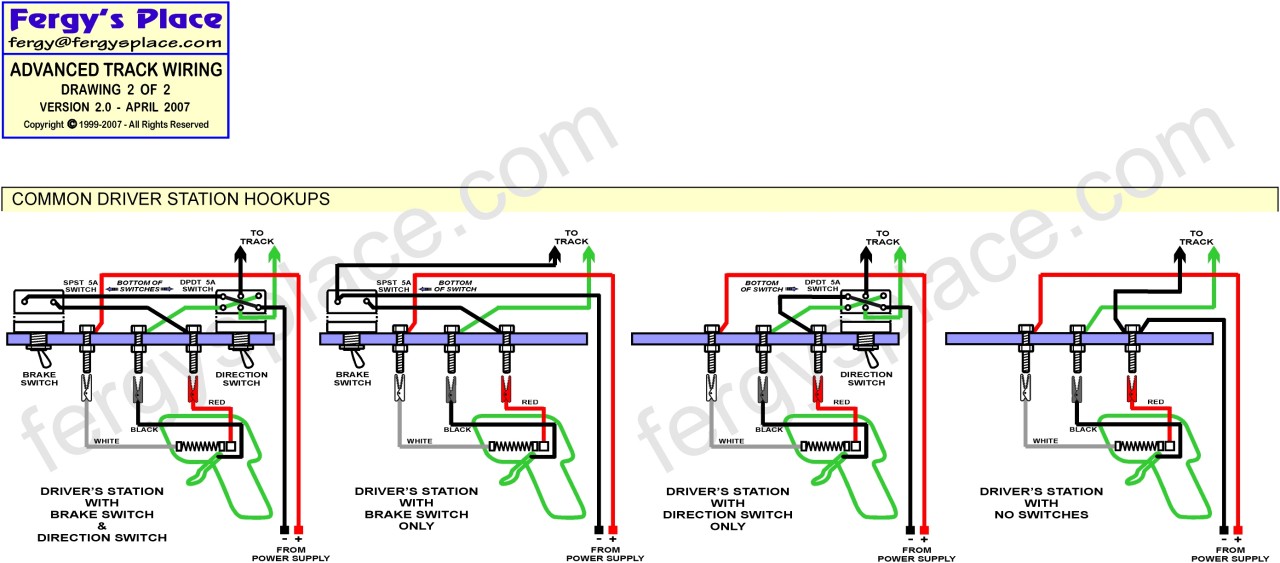
All of those switches tend to confuse matters. Most computerized racing programs add on/off relays as well as more fusing. The 8 amp line fuse can be increased to 20 amps for most commercial track use and use that 'brake switch' location for a circuit breaker to save cross-wired controllers with a five to ten amp breaker - there is no load on that side and the red/ground side of the track has a separate line to the power source. Rental track programs usually can trigger a relay for each lane and club tracks only need a master relay to turn all lanes at once. Be certain that the 'master' relay and fuse can handle the entire race field, rather than each lane. Size wiring to handle the loads as well.
Larry D. Kelley, MA
retired raceway owner... Raceworld/Ramcat Raceways
racing around Chicago-land
Diode/Omni repair specialist
USRA 2023 member # 2322
IRRA,/Sano/R4 veteran, Flat track racer/MFTS
Host 2006 Formula 2000 & ISRA/USA Nats
Great Lakes Slot Car Club (1/32) member
65+ year pin Racing rail/slot cars in America
#5
racerchaser96
-
- Full Member
-
- 36 posts Joined: 19-January 16
Rookie Keyboard Racer
- Gender:Male
- Location:Attleboro, MA
Posted 24 January 2016 - 09:26 PM
I just bought my track and all the wires are mostly red it's kind of confusing to follow all the wires if your a newbie like me not to mention trying to figure out the dead spots and braid. I'm kind of overwhelmed I want to get it done and do it correctly.
I wish there was a way to test to see if I had all braid correct going around the track.
Also the controllers has to be switched out were they plug in. It has a one plug style with on off or direction switch. I just want to use the red white black pins
I wish there was a way to test to see if I had all braid correct going around the track.
Also the controllers has to be switched out were they plug in. It has a one plug style with on off or direction switch. I just want to use the red white black pins
John Greaves
#6
Steve Ogilvie
-

- Subscriber
-
- 608 posts Joined: 17-November 14
Race Leader
- Gender:Male
- Location:Kincardine, Ontario, Canada
Posted 30 March 2016 - 12:36 AM
If you are in possesion of a former commercial track the drawings posted earlier are of no use at all to you .Nice drawings but not what you need .If the wiring is still intact on your track and you have not messed with it , then all you need to do is connect the tails under each lane to the braid .If it all worked before , it will work again . If not , watch this thread tomorrow and there will be a wiring diagram you can use .I need to make one for my own thread anyways ...
#7
Steve Ogilvie
-
- Subscriber
-
- 608 posts Joined: 17-November 14
Race Leader
- Gender:Male
- Location:Kincardine, Ontario, Canada
Posted 07 April 2016 - 09:10 PM
Sorry I have not got around to doing a wiring diagram .I still have to go to work for a living .Sometimes I bite off more than I can chew .
- TheRaceman likes this
#8
Ramcatlarry
-
- Subscriber
-
- 2,907 posts Joined: 08-March 06
Posting Leader
- Gender:Male
- Location:St Charles, IL 60174
Posted 08 April 2016 - 12:09 AM
Usually things are right when:
1) The (+) Positive power supply post is wired only to the white controller post. Color code it with white tape. If each lane has a separate relay, then each lane is unique, otherwise it does not matter, all white posts will have continuity when 'ON". SHOULD HAVE A FUSE rated for the fastest motor used before the white post.
2) The black controller post is wired only to the right braid for that lane. Color code it with lane colored tape.
3) The red controller post is connected to the left braid and the (-) negative power supply post. With a common ground, all left braids and the red post of all lanes will have continuity. Each lane should be fused for 5 - 10 amp to save controller shorts.
4) Automatic reset circuit breakers work fine.
Larry D. Kelley, MA
retired raceway owner... Raceworld/Ramcat Raceways
racing around Chicago-land
Diode/Omni repair specialist
USRA 2023 member # 2322
IRRA,/Sano/R4 veteran, Flat track racer/MFTS
Host 2006 Formula 2000 & ISRA/USA Nats
Great Lakes Slot Car Club (1/32) member
65+ year pin Racing rail/slot cars in America
#9
Steve Ogilvie
-
- Subscriber
-
- 608 posts Joined: 17-November 14
Race Leader
- Gender:Male
- Location:Kincardine, Ontario, Canada
Posted 13 April 2016 - 11:39 PM
Well said Larry .I put a diagram in my build a track thread in the tech section .


