This is an old thread and was pretty well "broken" so I've tried to get it fixed up and moved from the Hinterlands to my sub-forum. So here goes:
I moved this construction article from the old forum. I'd like to finish it here so Adam can see his car being completed. I've cut and pasted all my posts from the old thread into what might be the longest single post in history  . So here goes:
I'm finally getting started on this project and with the help of a new Nikon S1 digital camera I will try to show more of the construction steps I haven't been able to show in the past. I'm still learning the camera and hope the lighting and pictures will get better as I go along  .
.
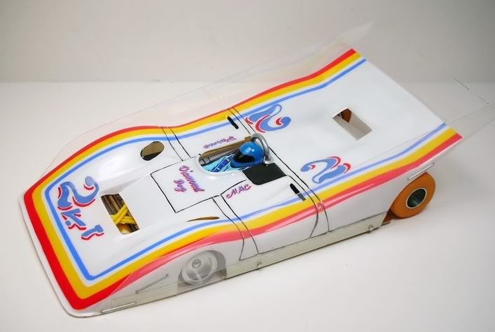
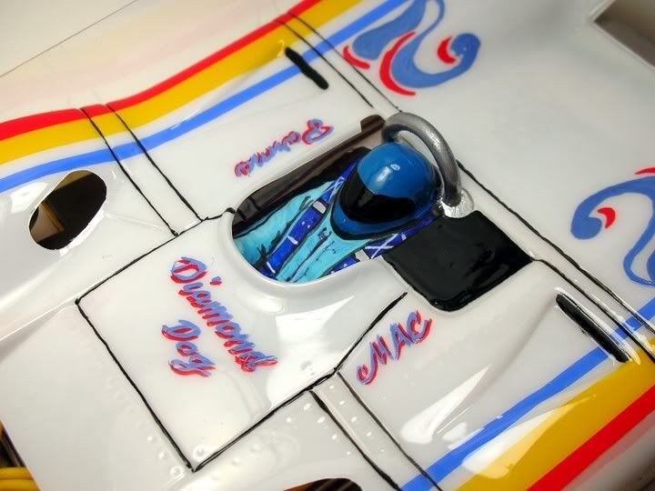
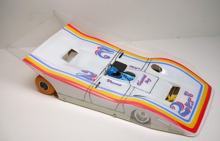
I am not trying to do an exact "clone" this beauty but rather do what we did back in the day......see pictures of a race winner and set about building one from the pictures. It will be as close as the parts I have will allow.
This is the version we want: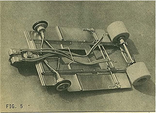
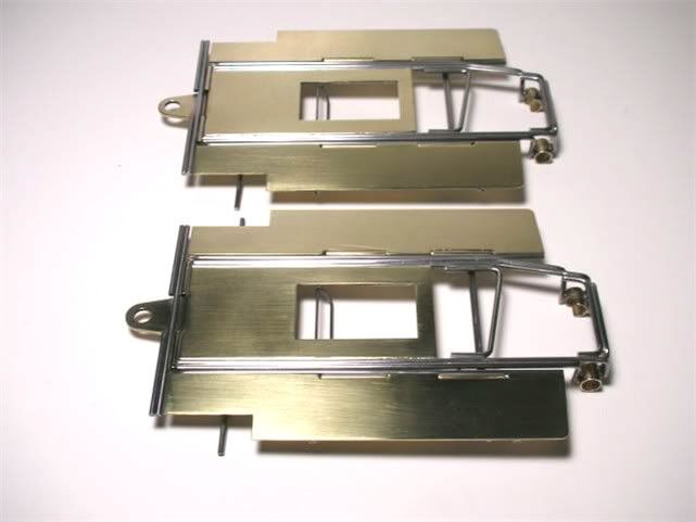
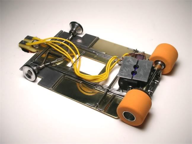
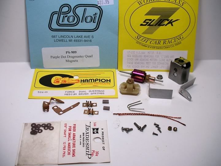
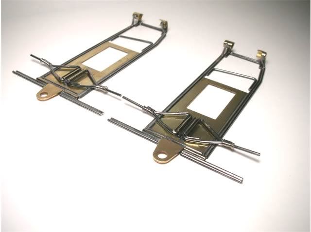
Here are the parts for the car, less motor: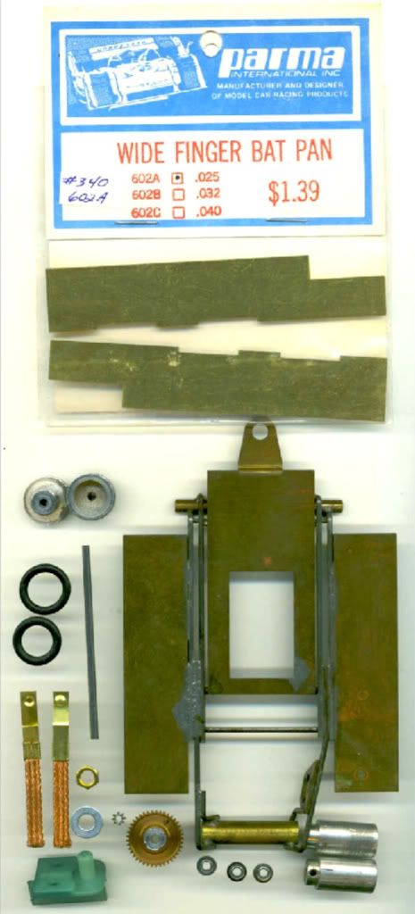
The drop arm is all we'll be using from that REH chassis. The Parma pans will be modified to look very much like the Neat Things pans. The front and rear wheels are Aguirres.....unless some Neat Things fronts turn up..... . Gears are a modern Sonic 8 tooth pinion and a vintage Fass 41 tooth spur. I wish I had a 42 or 43 tooth for a shallower motor angle but oh well, we'll make do.
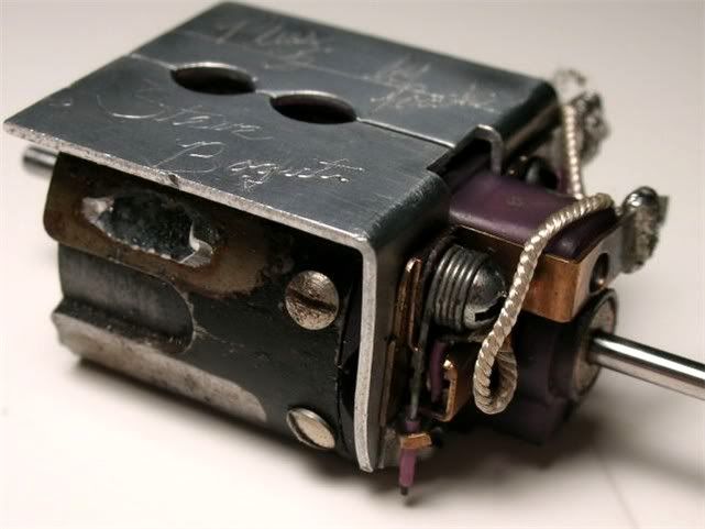
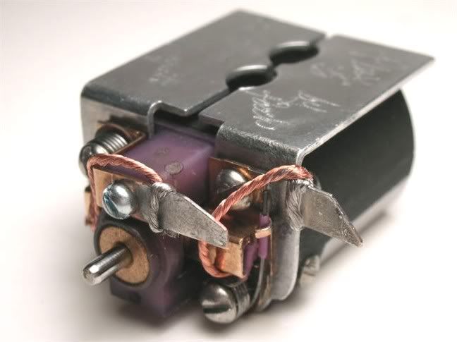
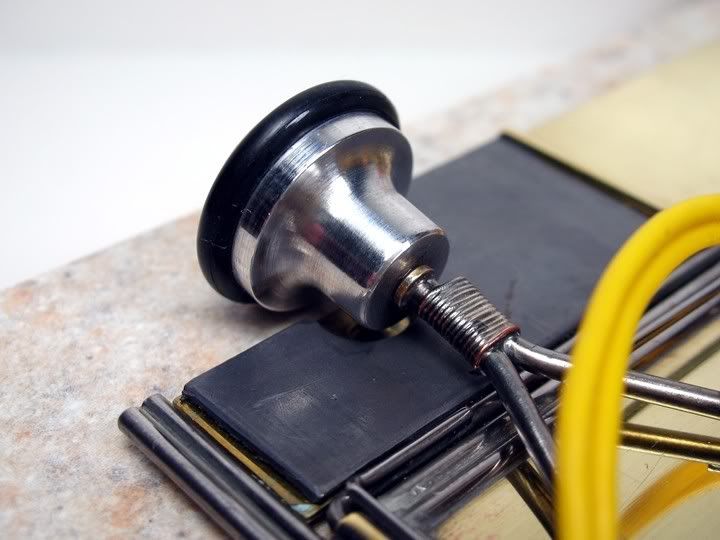
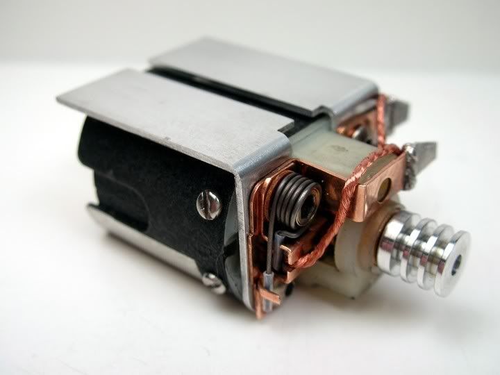
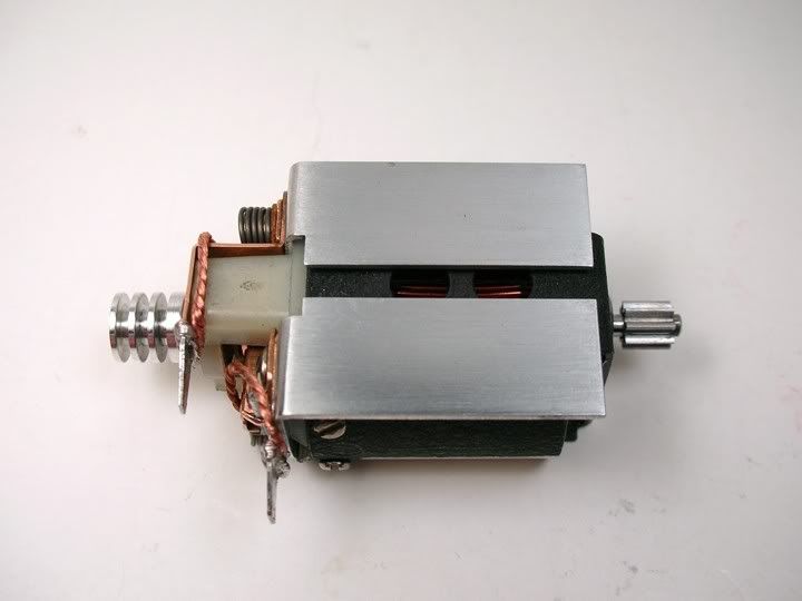
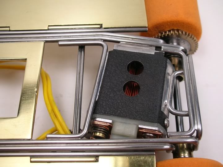
Here's the motor, axle tube, gear and jig wheels, all centered up in the jig: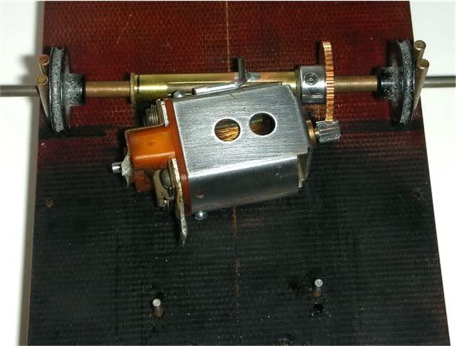
The axle motor is temporarily soldered to the axle tube with a wire brace. The axle tube is 1.250" long and is notched for motor clearance. The notch is .100" from the gear side and .250" from the end bell side. The depth of the notch is about half way through the tube. After all the rear axle bracing is installed I'll cut out the center of the axle tube to make room for the third axle bearing.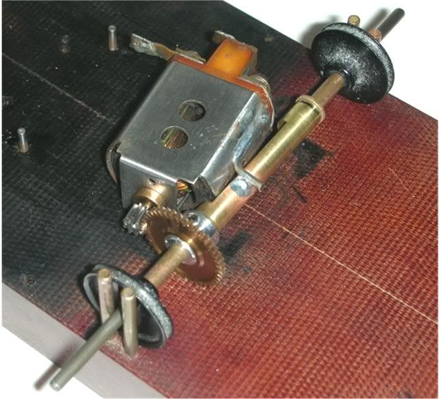
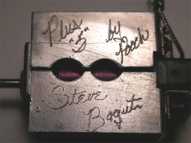
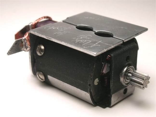
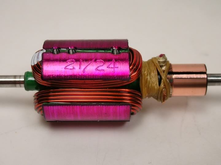
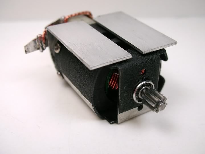
Just messing with the camera's Macro mode. Not too bad for a novice :teeth :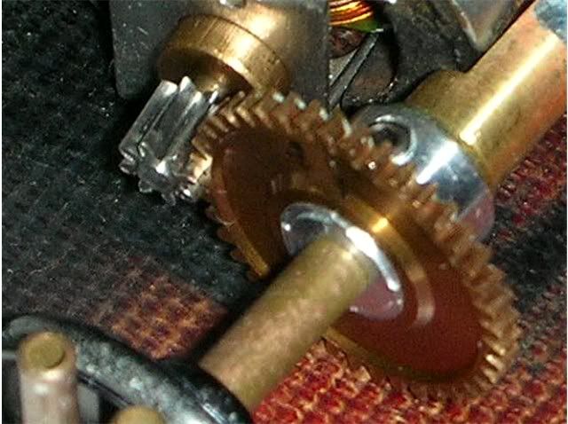
It's time to solder in the main rails.....
My digital camera skills are still lacking but here goes. Here are the 4 main rails of the chassis. I leave ends LONG until I've "convinced" them to take the shape I want. Piano wire is cheap. Oh, one thing I noticed with this batch of hobby shop piano wire was that some of the pieces were not straight.....kind of wavy. Now I spin each piece with my fingers to see if its straight and running true: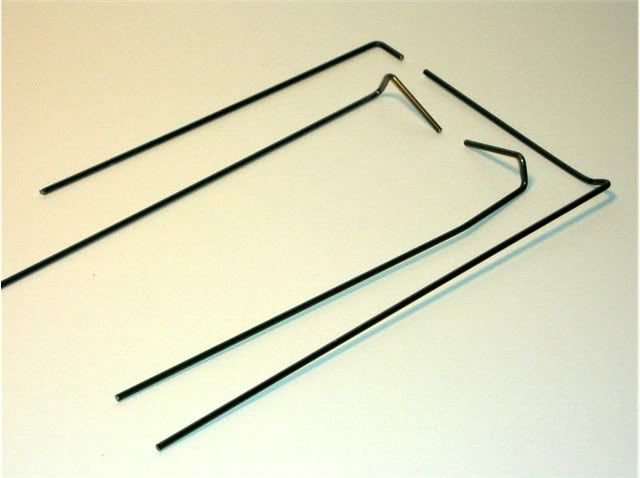
Here's the start of the center section in the jig. Next comes the 2 rear axle braces and cutting out of the center of the axle tube: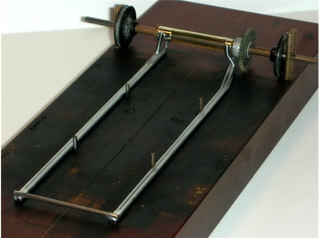
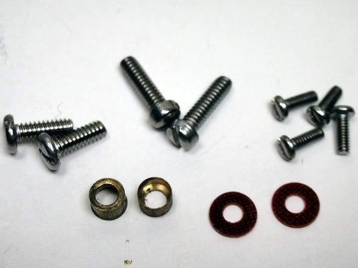
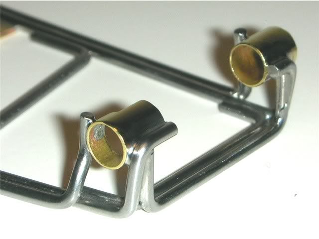
I'll also need to trim the main rails to length. For that I'll need the drop arm with all its plumber hinge tubes and bumpers installed. Here are the parts for the drop arm: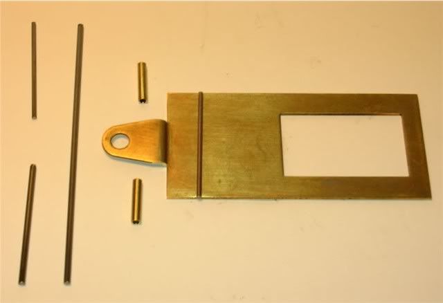
The wire sitting on the drop arm is .047" and is cut to the width of the drop arm. The two 3/32" diameter brass tubes are .475" long. The .062" diameter wire bumpers are left long to be trimmed even with the pans latter.
These are the soldered up parts in the drop arm jig: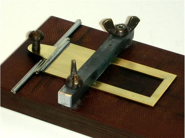
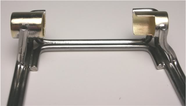
And the finished drop arm awaiting the Diamond front axles: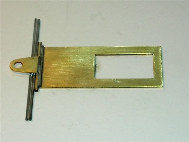
ONWARD!
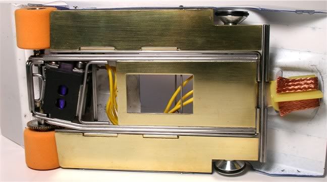
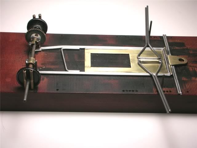
Here's where we're at so far on this project. I need to get a good light source for my photos. Sorry for the inconsistency: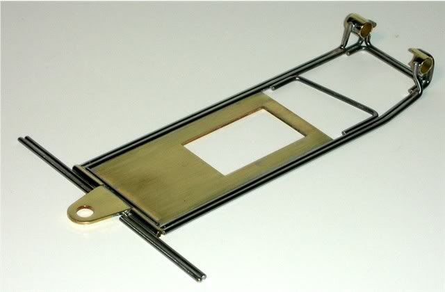
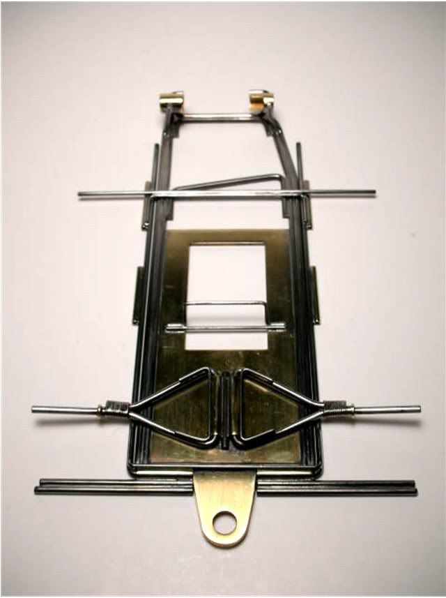
This is how the main rail were bent to meet with the rear axle tube. I don't know if it's the same as the original but this is what I did based on the old photographs. I think a car like this is a trial and error proposition. Just cut and bend a piece and if it doesn't fit, learn from your mistake and make a new one. Piano wire is cheap.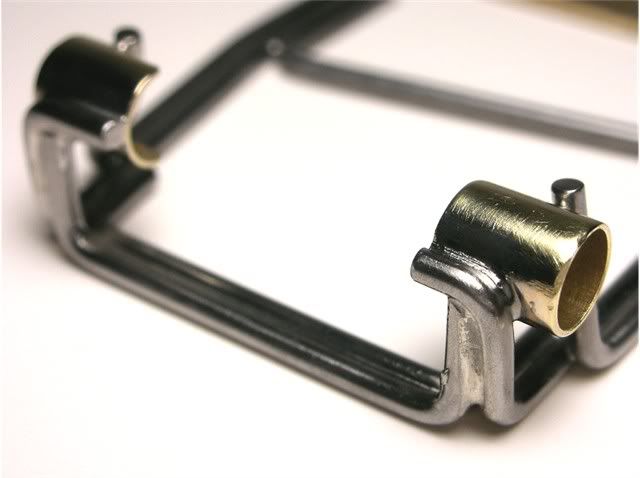
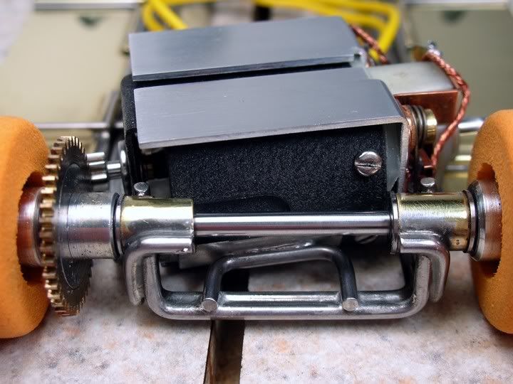
Here are the vertical and horizontal U-braces installed in the rear axle.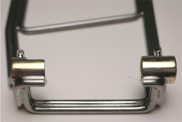
Next I'll bring the other center section up to the same point as this one and start on the "Diamond" front axles.
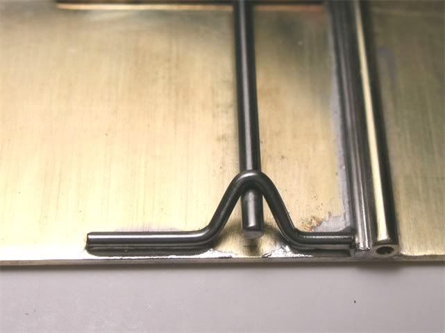
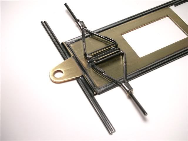
The front axle tubes are .570" long and are positioned one on each side of a piece of 1/16" piano wire which is centered on the drop arm. I used a machinist adjustable parallel to center the piano wire on the drop arm. Here is everything in the jig: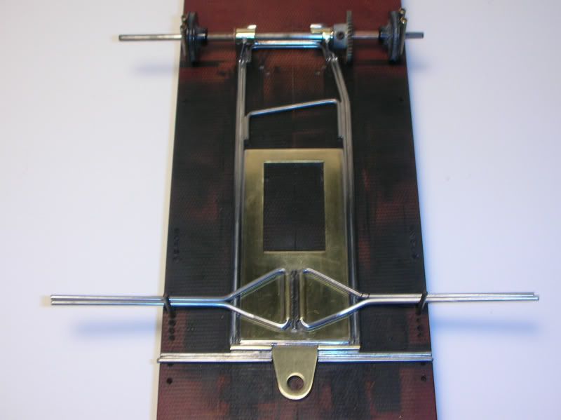
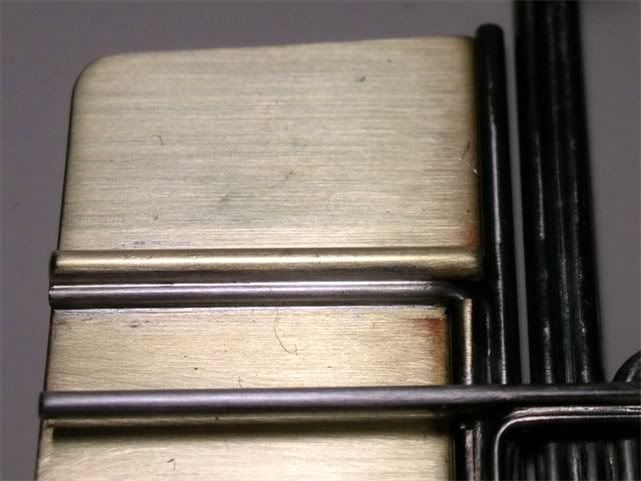
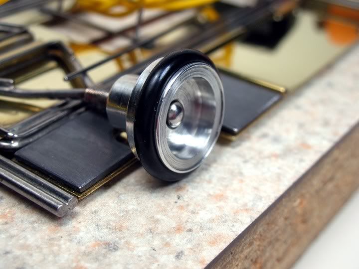
Now here is a little something I never would have known if I didn't have the "real deal diamond in steel" car in my hot little hands....well, plastic bag. I always thought the "diamonds" were flat but they have a nice little bend upward in the area I circled. The area behind the bend sits flat on the drop arm and serves as the axle down stop. The bend also positions the front wheel up higher closer to where they will be when the car is sitting on the track.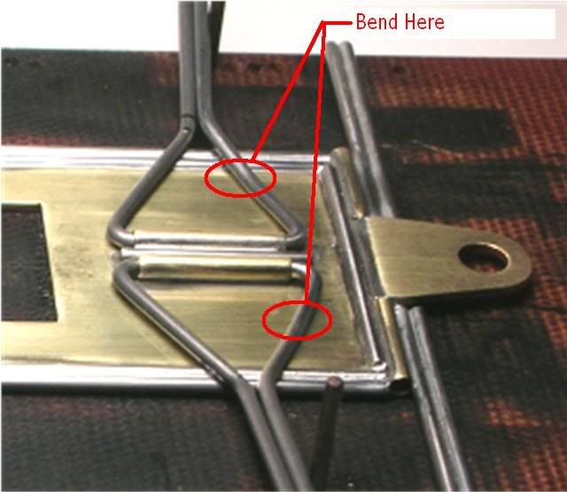
Well Adam that's as far as it goes until next weekend. I thing we had a good start over my holiday break. Once those front axles are on, the rest is gravy .
I've got the diamond axles all wrapped up in copper wire and finished on one chassis. I hope the next one will be easier :ahem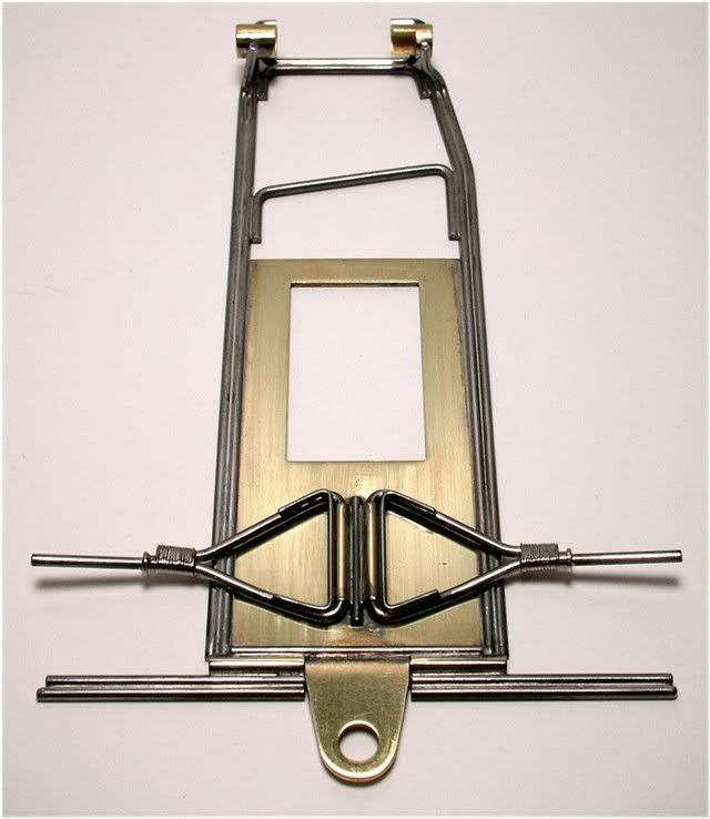
Great days! The Diamond front ends are done :bounce . I took some more pictures of the process on the second chassis. Here is a Diamond front axle ready for installation. Note the marks where the bends were made. I make them quite prominent because I know I'll have to go back and bend and re-bend to get things right: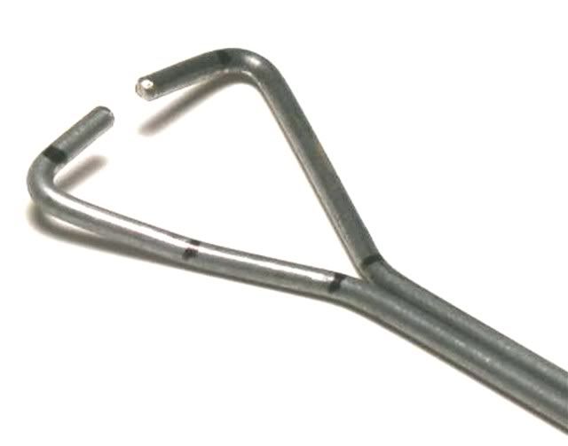
Here the axle is installed and getting all wrapped up with copper wire: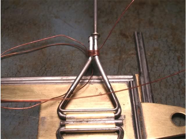
This is the finished axle: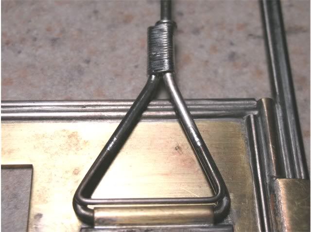
The wrap job: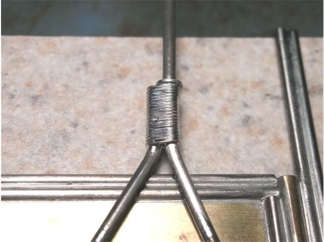
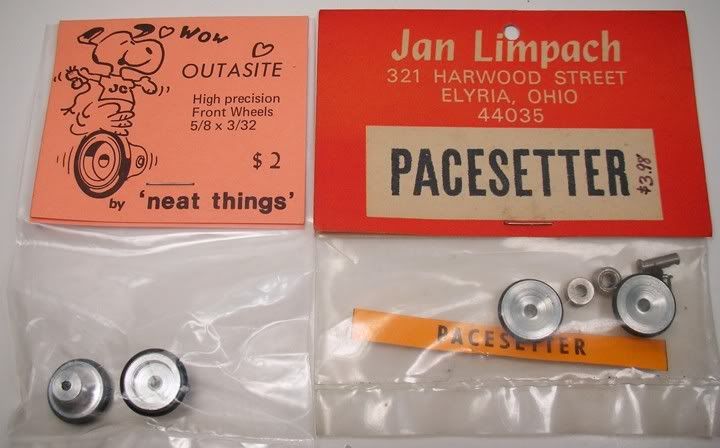
These are the front wheels that will go on Adams car if he can't get some Neat Things wheels: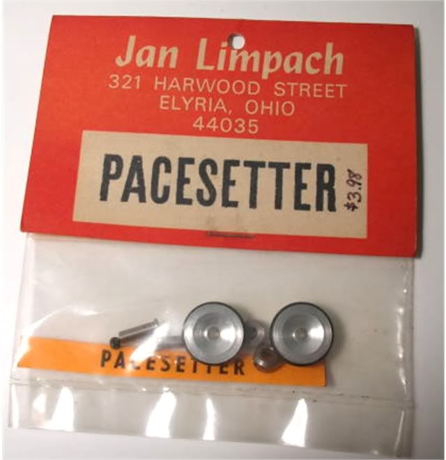
Well actually he's not getting my new in the package wheels...he's getting these: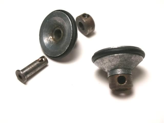
Looks like I have a little work to do on those.
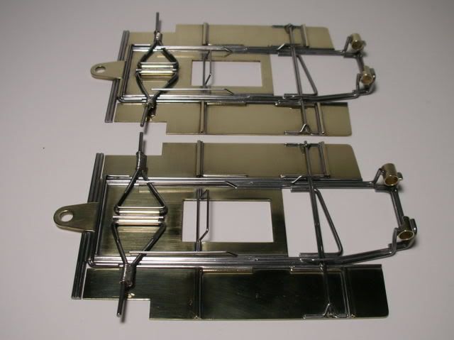
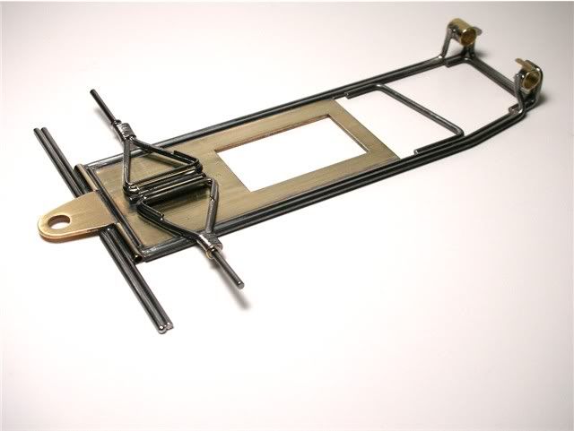
So here's where the twins are now. It's time for the plumber rails: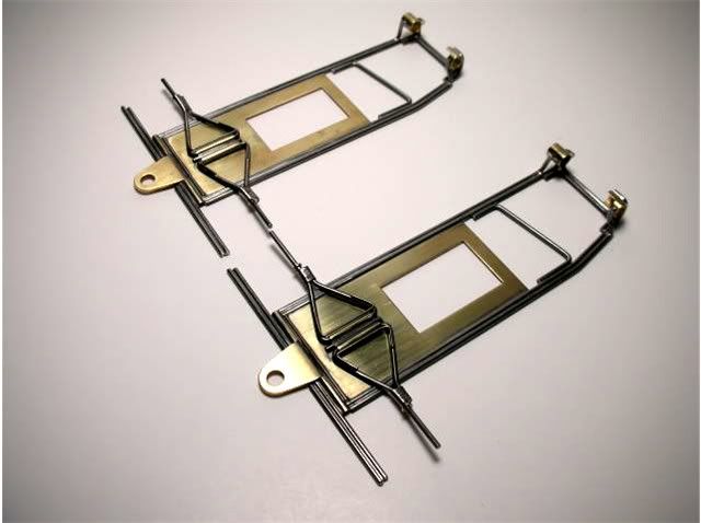
OK folks, as long as AroDyn has given away my secret for cutting metal....or donuts I might as well share a few other of my favorite tools. Jairus, I bend hobby shop piano wire with these: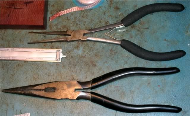
Any small mark the pliers make I sand smooth with some 320 grit sand paper. Philippe had a cool wire bending fixture and I believe used an exotic, super hard wire back in the day. But for me, it's hobby shop wire and pliers. We had an incident with one of my chassis and it became intimately acquainted with the wall on the BP Blue King. None of the bends broke because of the tight radius the pliers cause. The chassis did bend however. Maybe if it had been made out of the Dokk's exotic wire the chassis wouldn't have even bent! The Dokk's wire required a bending tool to keep a nice radius on the bend which kept the very hard spring steel wire from fracturing on the bend.
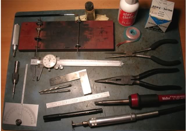
Anyway, here's a look at part of my work space with a few of my old favorites. As you can see nothing exotic I have the light saber in a special drawer: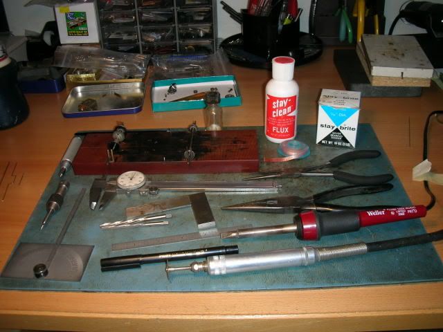
Now it's time to put those tools to, hopefully, good use. We need to make plumber rails to hang our bat pans off of: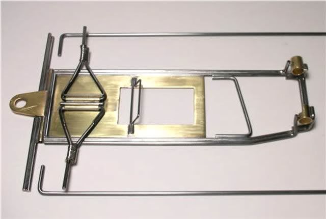
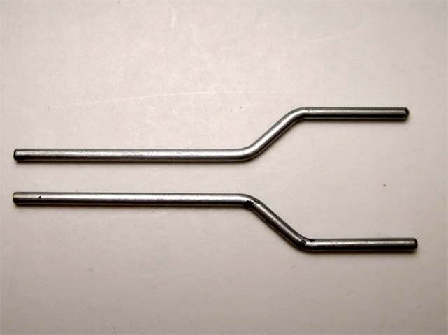
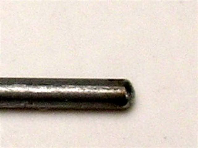
No big deal, just some 90 degree bends in some .062" piano wire right? Not quite. I don't know what the good Doktor used on this original but I do know what he used on his "Diamond in Steel". He used .055" wire for a nice free plumber movement. One more thing to remember, just as Lee Gilbert showed us in his famous Car Model Magazine article... you need to get kinky with your plumber. I mean you need to put a slight upward kink or bend in the rail to compensate for the thickness of the plumber hinge tube. If you don't it will look like this: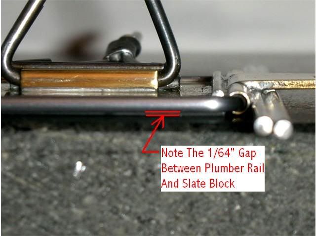
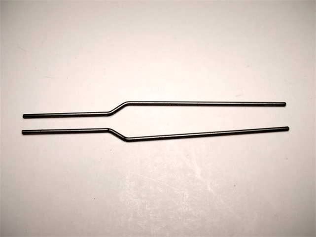
Get kinky and add the extra bend and it will look like this: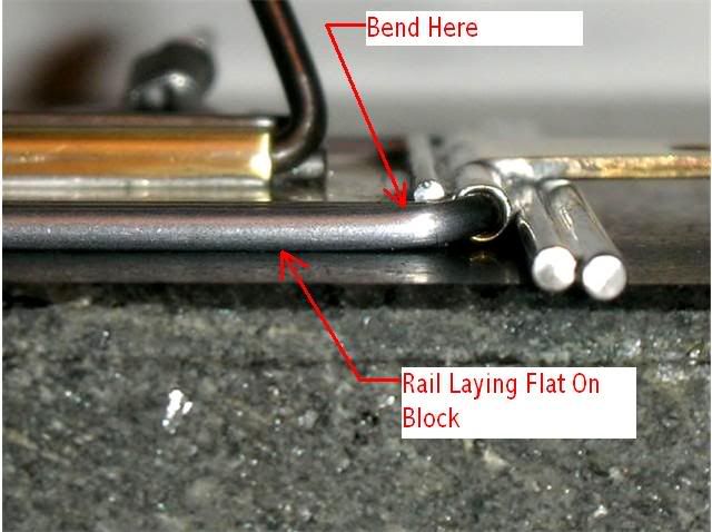
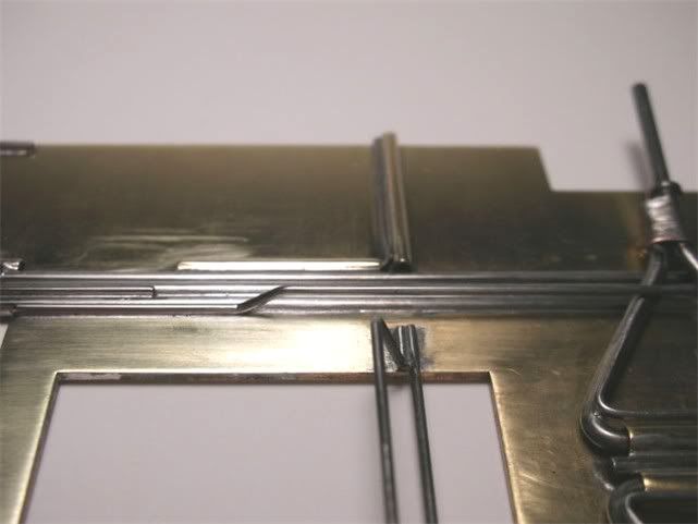
Next, Lee said to install the plumber rails onto the center section with the cross pieces, THEN solder the pan hinge tubes to the plumber rails. I solder the hinge tubes on first. Why, one word WOW or is it WARP or BENDING or whatever you call it, heat up the rail to solder the hinge tubes on and it will look like this: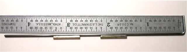
A close-up of the amount of bending: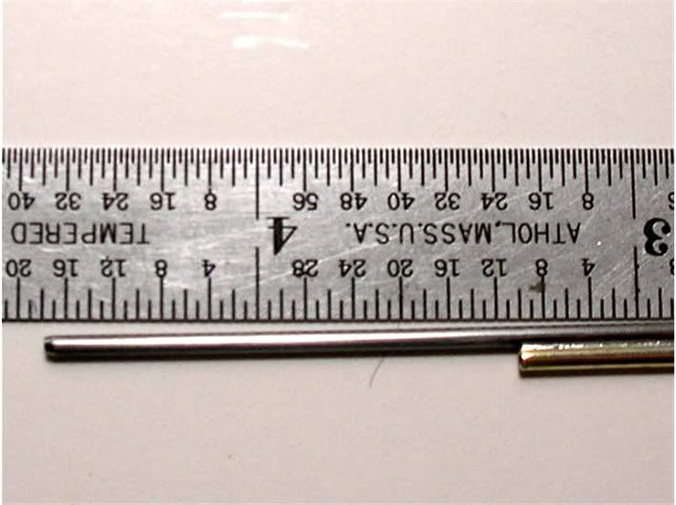
This would be instant "Bind City Earl". Lee straightened out this whole mess while on the center section. I like to do it now and then attach the plumbers to the center section. I'll tackle that next.
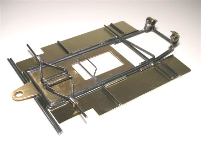
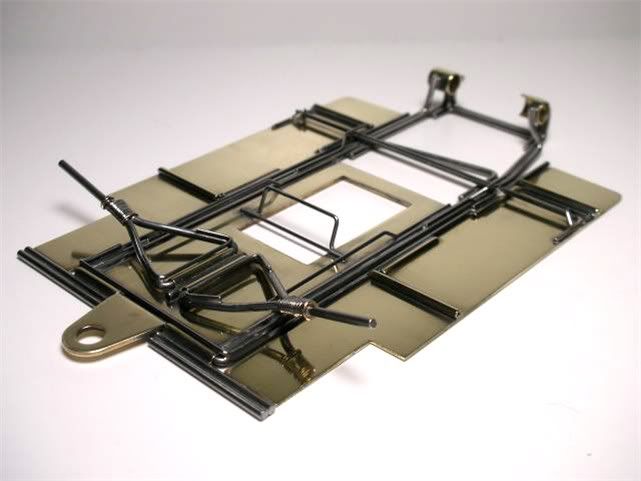
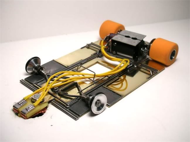
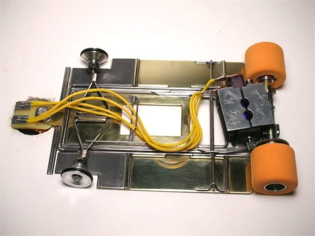
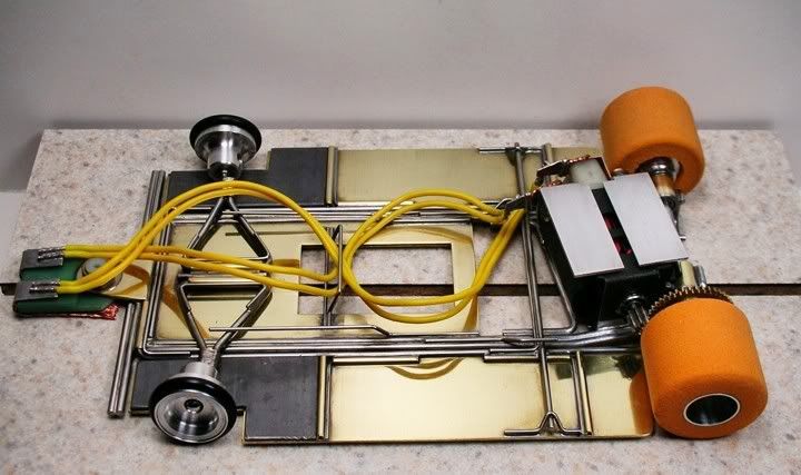
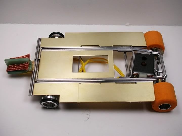
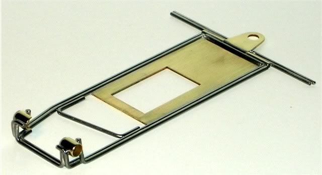
I've got the plumber rails installed on one of the chassis. Also, notice the lead wire retainer on the "drop arm". Here's what it looks like so far: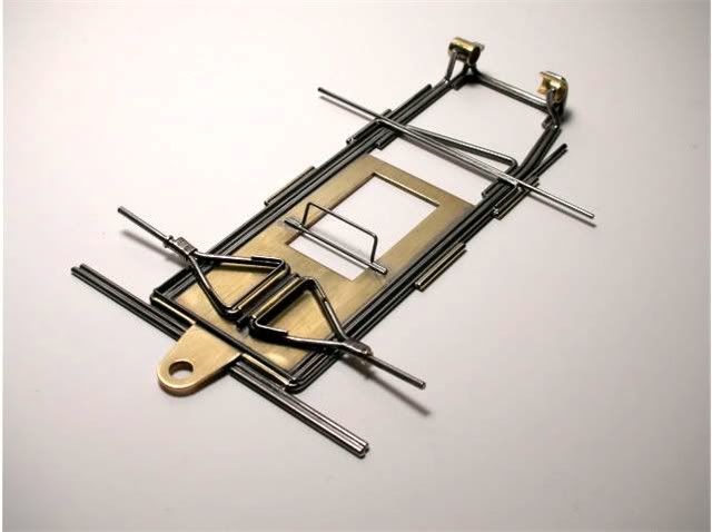
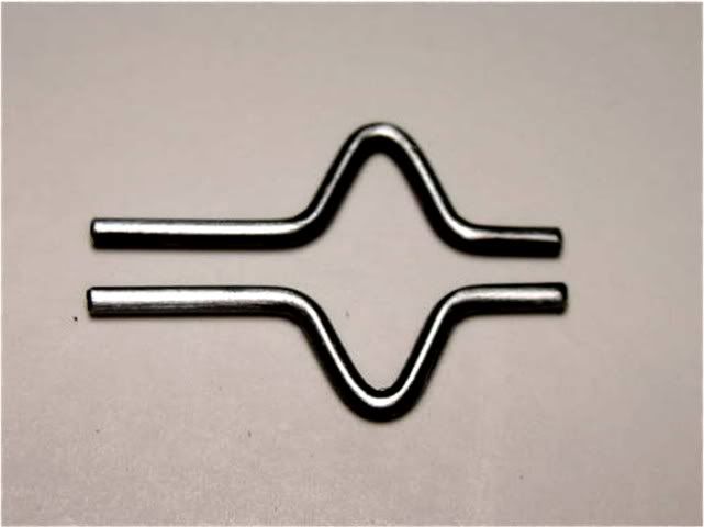
Here is the front plumber rail connector. It needs a bend to conform to the kink we put in the plumber rail.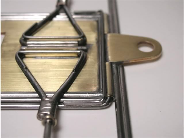
This is a close up of the connector on and off the chassis: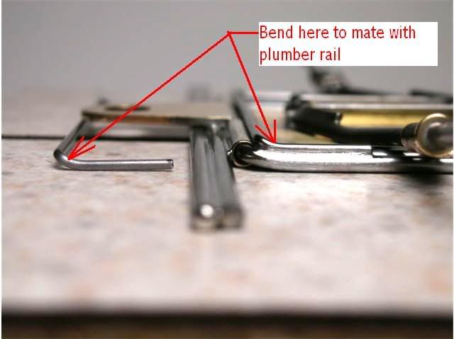
The rear connector needs a little tweaking also. The connector arm that gets soldered to the plumber needs to be bent downward to nest in between the pan hinge tube and the plumber rail. This adds a little bullet proofing to the whole enchilada: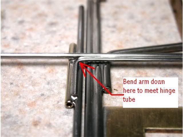
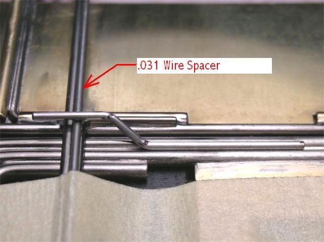
Since the pan hinge tubes are bigger in diameter than the frame rails we need to file a little flat in the hinge tube so the rear plumber cross piece will lay flat on the frame rails. This serves as the downward stop for the plumber rails. We want everything to be inline so the chassis will be nice and flat: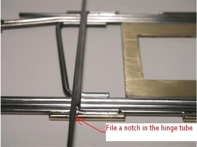
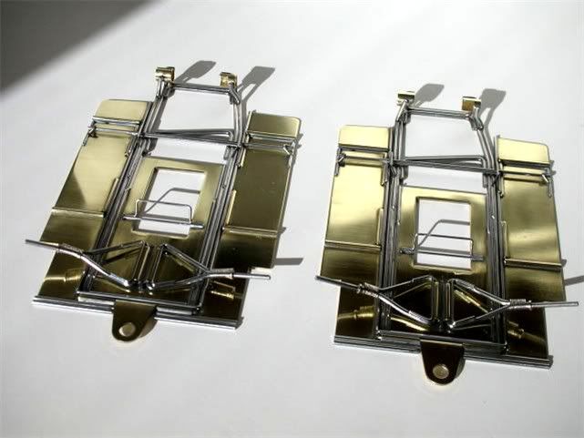
Next I get to repeat everything I just did on the other chassis. Then it's pan city 
Both chassis are ready for floppy pans. Make sure you pan hinge tubes have a nice chamfer if you like to be neat Pete: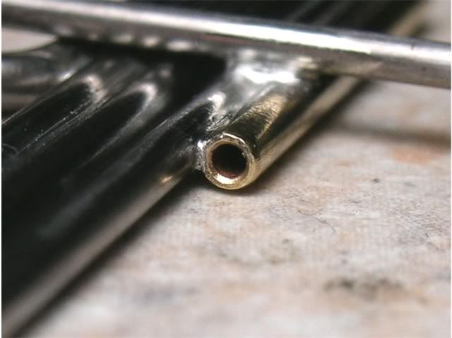
If you just stick a piece of piano wire bent at 90 degrees in the hinge tube this is what it will look like....BAD: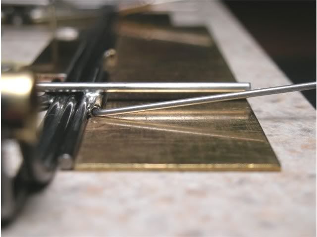
We want it to look like this: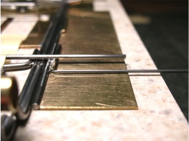
This just a bend and a notch away. Bend the hinge slightly where shown: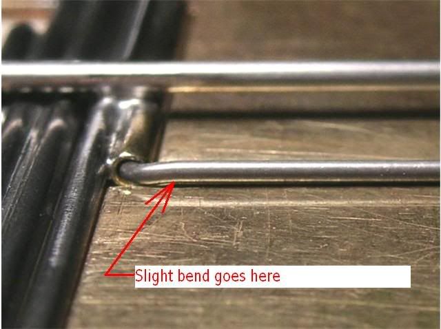
Now mark the pan on both sides of the hinge: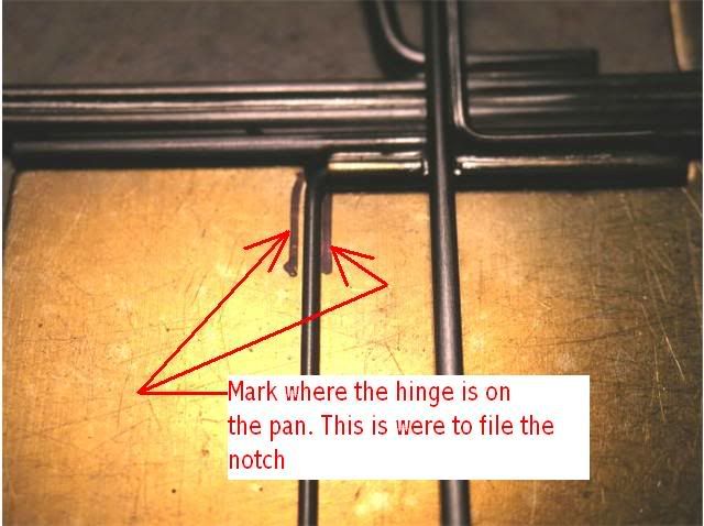
File a little notch with a rat-tailed needle file like this: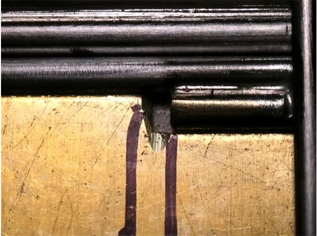
If you're building 2 chassis at once like I am repeat the above steps 7 more times and you'll be ready to solder on the pans.... ....next weekend.
Now to finish mounting the pans. First we need to cut a 3 degree angle in the end of the pan. This allows the pan to be very close to the tire and still clear it when the pan tilts upward. I trim each pan individually on a disk sander. I also put a 3/32" radius in the rear corner of the pan, just like the Dokk's. Then I clamped all 4 pans together in a little drill press vise and finished them together with a file. This way all 4 are the same: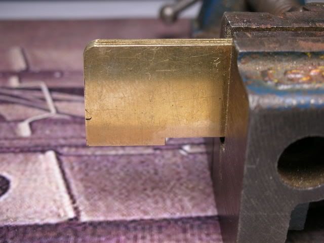
This is a finished pan on the left. Stock pan is on the right: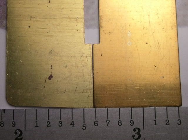
Now is a good time to sand the **** out of the pans. I use a sanding block and 320, 400 and 600 grit sand paper. I sand the bottom of the pans length-wise and the top of the pans side to side. You'll see why in a minute. When you turn the pans over to sand the other side it helps to use some clean paper to set the pans on while sanding. This way you won't scratch up what you just did with sanding debris. I always seem to have plenty of old PayPal receipts to use for this :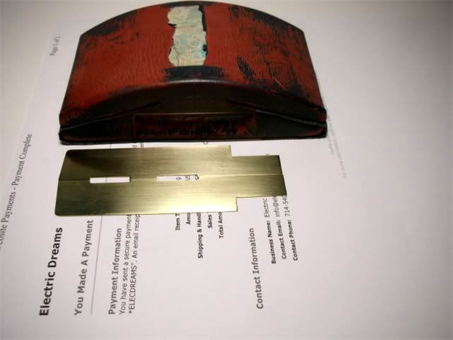
I like to use a square and draw a line across the pan to help me align the hinge wires. Even with this I still can't seem to get them as aligned as I'd like. My hat's off to the pro builders of the day who could just "eye ball" things and get them right.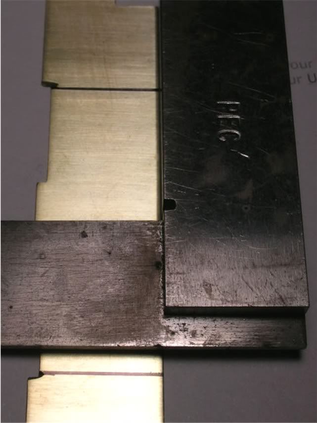
This is the pan hinge wire more or less lined up with the mark I drew. It's time to start soldering: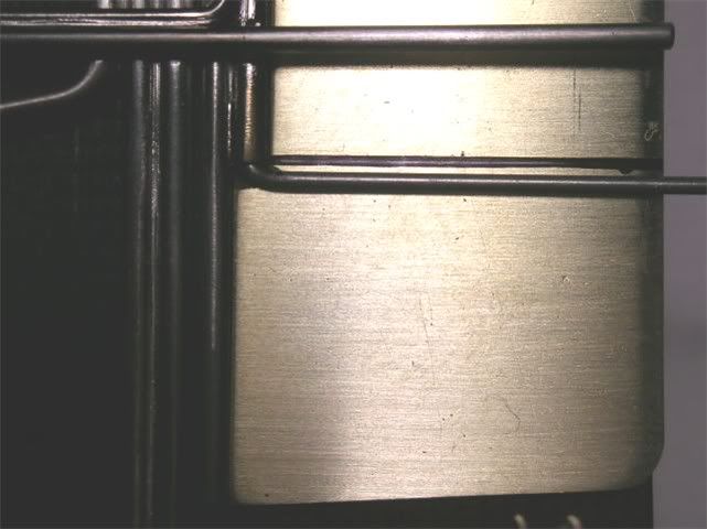
Oh my, what a mess. I know it looks ugly but all will be well. I put the tip of the soldering iron on the outside of the pan hinges. This tins the area where the body mounting pin tubes will be soldered next: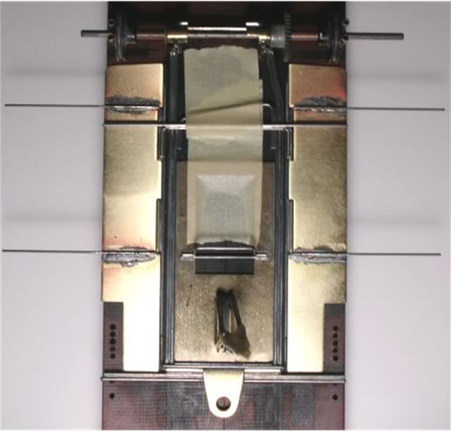
I leave everything long for a reason. You may not need to do this but it helps me. I lay the tube in place then put a drop of solder out at the end to tack it in place: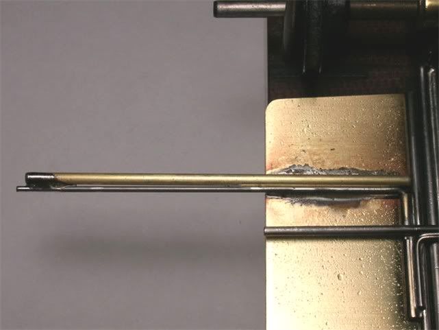
I use an old E-Xacto knife with a modified #11 blade as a "holder in place gizmo":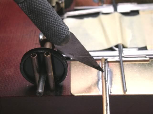
Grind a little notch in the end of the blade with your cut off wheel: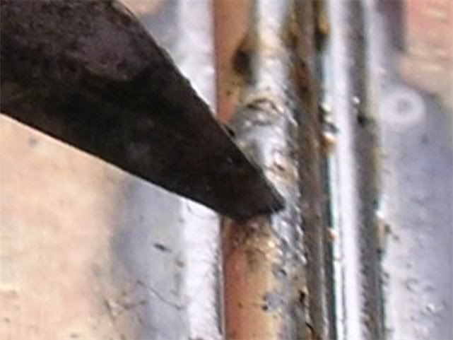
Put the tip of the iron not on the pan but on the top of the pin tube along the hinge wire. With enough heat and flux the solder will wick down along the pan. This makes cleaning up the pans much easier. I also use that extra length of tube to "pull" any extra solder out of the joint. See how the solder joint is continued way past the pan: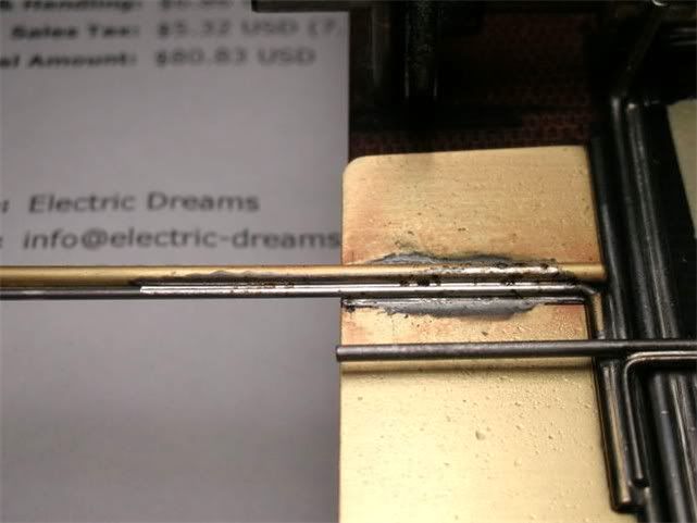
More to come.....