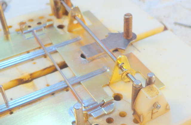
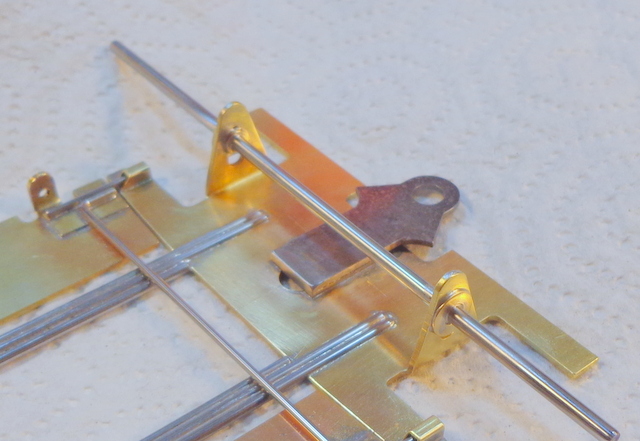
In recent past, I’ve done a lot of tech overviews talking about chassis designs and performance and stuff. What I haven’t done for a while is a step by step on anything. This article features a fairly simple 4 ½” Stock Car built from the latest evo of R-Geo Ricks new chassis plate. The design is pretty simple so what I’ll be doing here is focusing on some details that some newer builders may find useful.
Kits are a wonderful way for the novice builder to get his/her feet wet but they can also make really good race cars for the more serious builder. The difference between the two types of builder may be that the more experienced know that you don’t just open the bag and basically shake out a finished product onto the table.
So….for this build, here’s what we are starting with…..Ricks newest iteration of the Stock Car plate.
- Plate is .040 thick.
- Dragonslayer type pan hangers are .032.
- Guide tongue is .042 hard steel.
- Bracket is .050 Z-poid (angled face)
Plate with some dimensions and the pan cuts marked.
- Inner edge to edge of the rail slots = 1.00” to match the bracket width.
- Inside edge of rail slots are positioned perfectly but slots not cut for any particular rail setup.
- We’ll be using 2 rails/side of .062 in the slots so they’ll get widened to about .128”
That thing I harp about all the time……square up the bracket.
- Use a good file and push/pull the bracket face down the file with pressure.
- Then follow on each “leg” of the bracket.
- This’ll get the bracket face and legs flat.
- Now, screw in a beater motor and square up the legs to the motor/bracket face.
Now….get the rear bearings and jig wheels in place and get ‘er on a really flat block.
- Check that the bracket legs are flat on the block surface.
- Jig wheels are both sitting flat.
- Axle is parallel to bracket face.
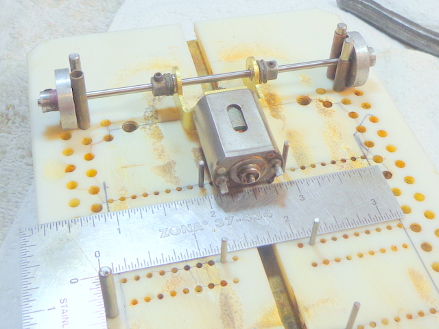
Into the jig and center the motor-bracket assembly.
- Jig wheels hold the axle in place outboard.
- Retainers from old spur gears inboard center the motor-bracket assembly.
- Square it again with the mini-square. (Zona or Exacto or Excel are all the same piece)
- You can see positioning pins in place here at 1.00" matching bracket and rail slots.
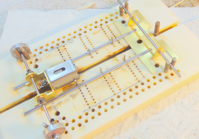
Lay out the components and rails in jig for trial fit.
- Jig has positioning pins in place at 1.00” outside-outside all the way down the jig.
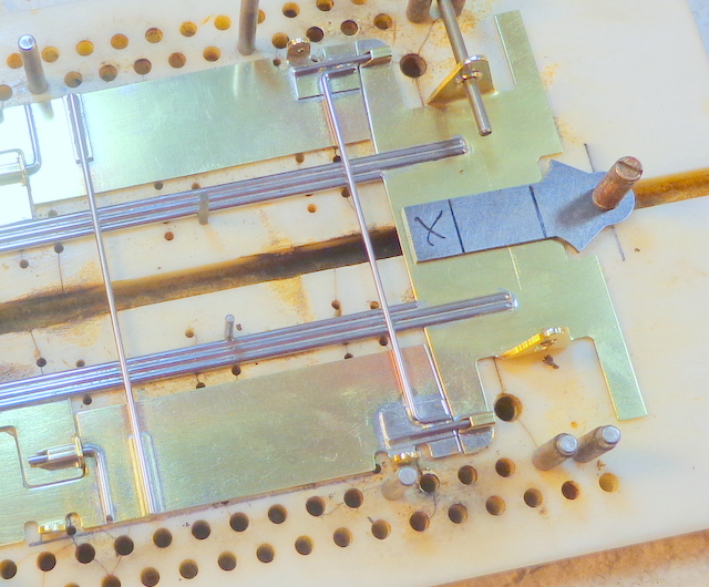
- You can see some marks on the rear pan hangers where they’ll need trimmed.
- 2 rails of .062 piano wire/side are laid in place to check fit in the widened rail slots.
- Near side front slot needs a few more more file strokes for an easy fit of the rails.
- The rails rest flush to the bracket, flush against the positioning pins and slip into the rail slots.
- Rails must hit all these marks and slip into the slots easily with no “spring” to them.
Ready to turn on the soldering iron…..YAY!!!!
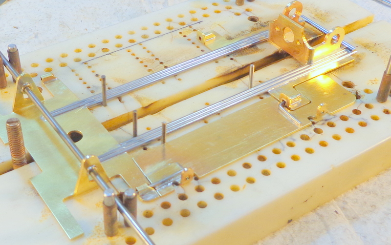
- Front axle upright slots are oversized so a JK 3/32” solder on retainer is used as a bushing.
- These will be soldered to the uprights but not to the axle. Axle will now be centered in slots.
- Axle not soldered in at this point so the axle can come in and out.
- Main chassis rails are aligned at bracket, pins and front and checked for fit.
Check for square one more time and then tack solder main rails at bracket and front slots.
OK....that's enough for tonight. I'll finish this up tomorrow.


