1237-Cb3+ Build Sequence, Prologue
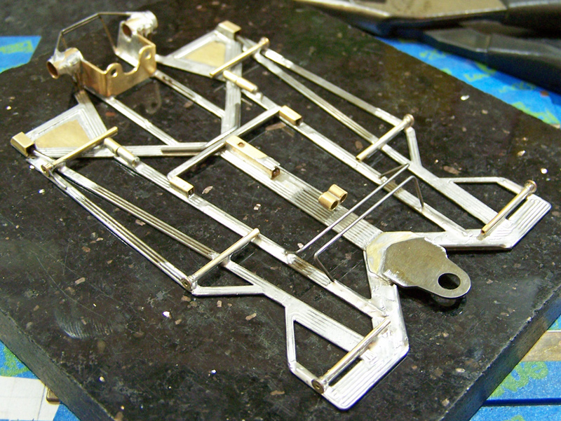
It occurred to me that this may be the last 1237 chassis I build, as the build progression is advancing pretty deep into the series designs and numbering system. It also occurred to me that I had yet to post a build sequence for any of the 1237-series chassis, and had yet to post a build sequence for any of the 0.032” wire framed chassis. So it was a “now or never” thing.
Besides, since the 1237 is the basis for everything being built of late, this was the one that needed to be posted for those few suffering souls who have been desperately looking at the chassis pictures trying to figure out what wires are where, which is dang near impossible, even I admit. All one or two of you will be happy to see that, compared to the latter 1219-series builds, like the 1229’s and 1233’s, the 1237-series are less convoluted; they also have much fewer multi-bend (more than 1 bend in a plane) wires, but this means they have more wires per structure component. The general rule of thumb I’ve learned, largely from observing chassis lateral loading characteristics, is: As the diameter of the wire used for framing decreases, the length of any wire component within the framing should be relatively shorter, and this has greater application medial as opposed to lateral in the framing. So, “More & Shorter” wires are sort of what you want for a 0.032” wire framed chassis.
While the 1237-Cb3 is a “short” chassis (3.75” WB / 4.75” RAX-GPC / 1.00” GL), all the wire framing and build sequence is the same for all 0.032” 1237’s regardless of dimensions. Since this is a CanAm Plus (“+”) class build, the dynamic pans are not part of the chassis build, but those were the easy parts for anyone to figure out… relatively speaking… maybe…
So, here goes for the few guys who’ve asked, and maybe some weird sort of entertainment for the rest of y’all.
My apologies for any blur in the photos, but this was a quickie Bend-Solder-Click process.
Descriptions are above each picture.
All wire is 0.032”, unless stated.

CMF3 1237-Cb3+ build sequence
#1

Posted 23 March 2017 - 03:00 PM
- Greg Erskine likes this
#2

Posted 23 March 2017 - 03:10 PM
1237-Cb3+ Build Sequence, Part 1 of 7
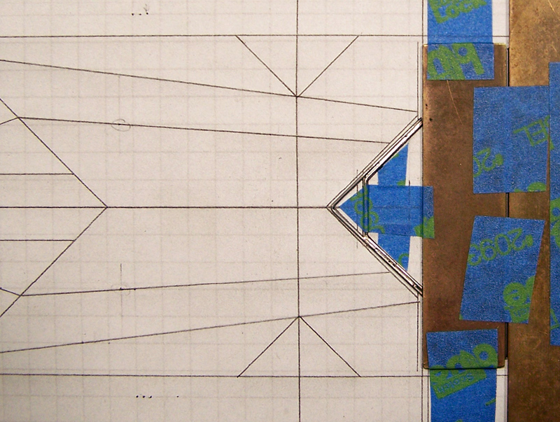
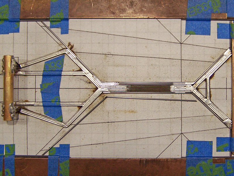
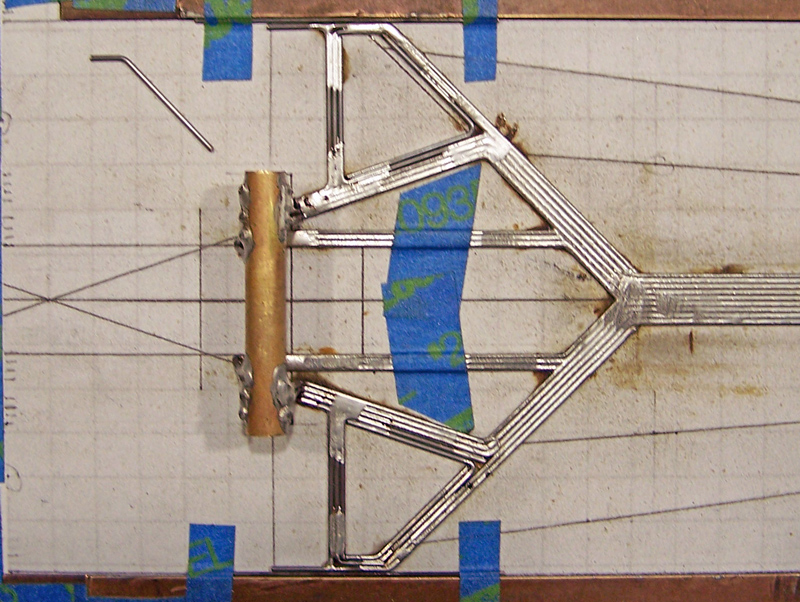
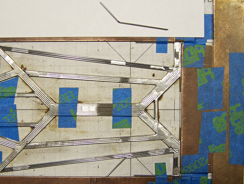
Picture 1: First of five wires comprising the front spanner structure; 2-bend wire, mid portion to set at front of guide tongue mount, with side portions projecting 45-deg forward; sides left long for easier flat fabrication.
Picture 2: Chassis front border defined by two brass plates with a piece of 0.032” wire between (to be removed later).
First front spanner wire trimmed to length and positioned.
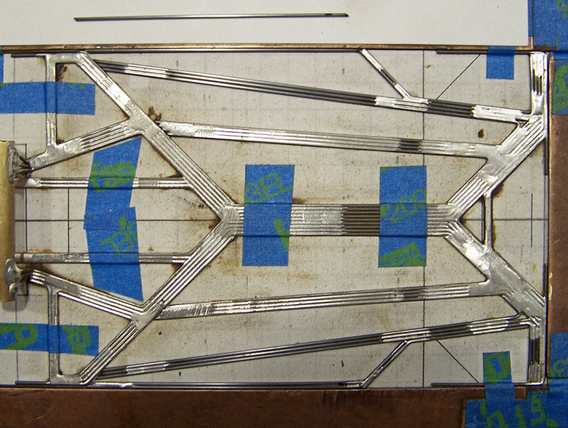
Picture 3: Second front spanner wire; 1-bend (90-deg); soldered to lateral aspect of side portions of first wire.
Picture 4: First of nine central main rail wires; 0-bend; centered and tack soldered to apex of second front spanner wire.
Picture 5: Chassis side border plates set. A piece of 0.032” wire is used as spacing on each side forward of the front axle line.
Third front spanner wires; two 1-bend (45-deg); soldered to lateral aspect of second front spanner wire.
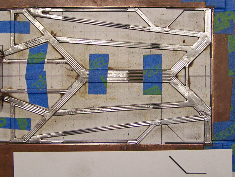
Picture 6: Second center main rail wires; two 1-bend; soldered to lateral aspects of front spanning structure “45’s” and first main rail wire.
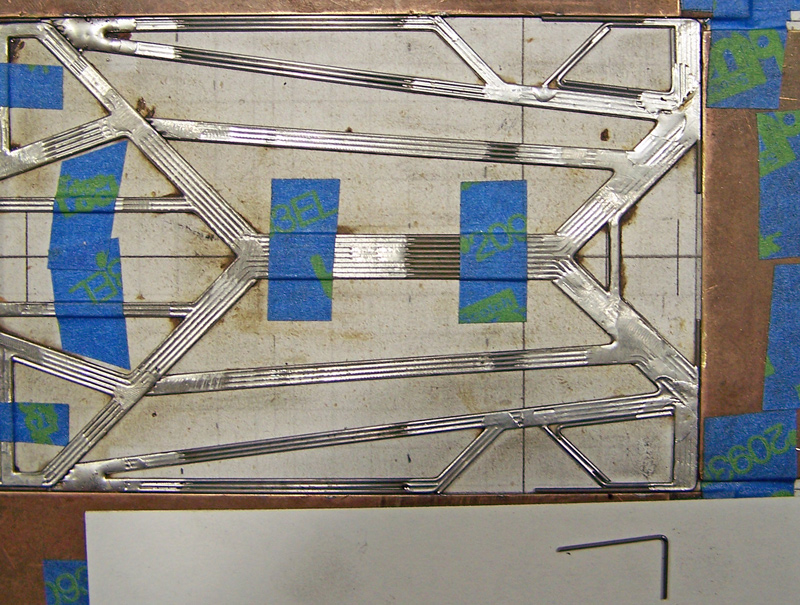
Picture 7: Third center main rail wires; two 1-bend (45-deg); soldered to lateral aspect of second main rail wires and projecting rearward (cut to length at projection line for the lateral rear axle tube support wires).
Picture 8: (…blur…) Last front spanner wire; a short piece of 0.039” wire to sit inside the forward aspect of the guide tongue mount “triangle” formed by the first and second front spanner wires.
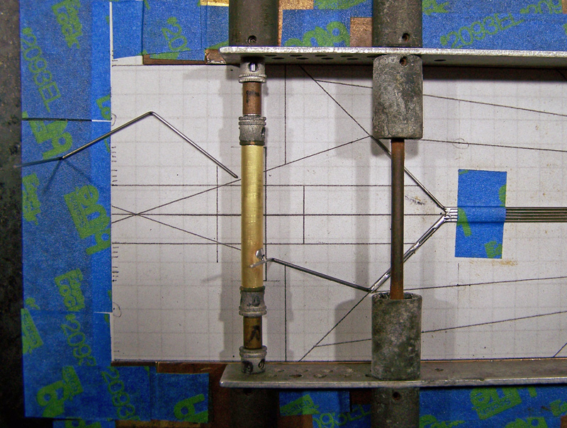
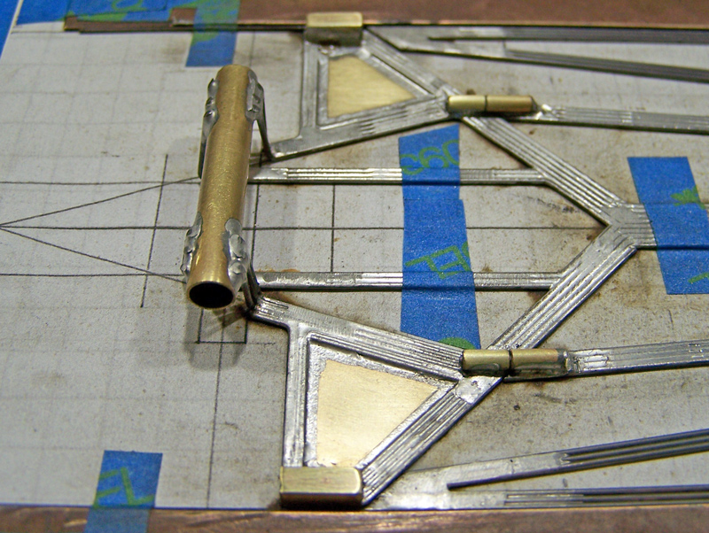
Picture 9: My ancient Champion jig (real hi-tech stuff… goes well with the graph paper and blue tape…) positioned, with 1.40” long 7/32” rear axle tube in place.
#3

Posted 23 March 2017 - 03:18 PM
1237-Cb3+ Build Sequence, Part 2 of 7
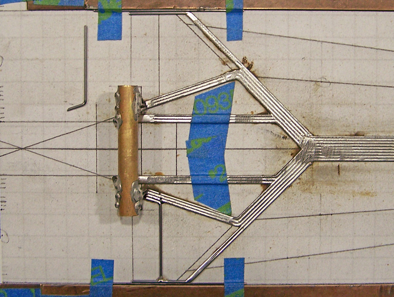
Picture 10: First of three per side lateral rear axle (RAX) tube support wires; two 1-bend (in chassis plane) with axle tube upright bend; soldered to medial-rear aspect of third center main rail wires, and forward aspect of RAX-tube.
Note: All lateral RAX-tube support wires attach to the front of the RAX tube.
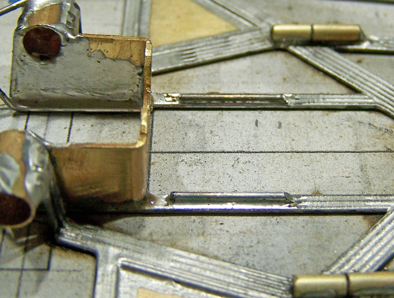
Picture 11: Second lateral RAX-tube support wires; two 0-bend (in chassis plane) with axle tube upright bend; soldered to lateral aspect of first lateral RAX-tube wire, and RAX-tube.
Picture 12: Third/final lateral RAX-tube support wire; two 1-bend (in chassis plane) with axle tube upright bend; soldered to lateral aspect of third center main rail wires, second lateral RAX-tube support wire, and RAX tube.
Note: Front view shows all six wires in place, and how uprights are angled for stronger support.
Picture 13: Notes: The medial RAX-tube support wires also form the motor box. All medial RAX-tube support wires attach to the rear aspect of the RAX tube.
The spacing for the medial RAX tube support wires is positioned (one 0.25” wide brass plate with a 0.047” wire flanking each side).
First of three per side medial RAX-tube support wires; two 1-bend (in chassis plane) with axle tube upright bend; soldered to medial-rear aspect of first lateral RAX-tube support wires, and RAX-tube.
Picture 14: Second medial RAX-tube support wires; two 0-bend (in chassis plane) with axle tube upright bend; soldered to lateral aspect of first medial RAX-tube support wires, and RAX-tube.
Picture 15: Third/final medial RAX-tube support wire; two 0-bend (in chassis plane) with axle tube upright bend; soldered to lateral aspect of second medial RAX-tube support wire, and RAX tube.
Note: Rear view shows all six wires in place, and how uprights are angled for stronger support.
Picture 16: Excess length of the twelve RAX-tube support wires trimmed; jig removed.
Picture 17: Fourth center main rail wires; two 1-bend; soldered to lateral aspects of second and third main rail wires.
Picture 18: On each side, along the side border brass plates, a 0.024” wire and a 0.032” wire are added for spacing located at the side of the (to be constructed) lateral rear static pans’ framing.
Fifth/final center main rail wires; two 1-bend; soldered to lateral aspects of second and third main rail wires, and projecting to 0.032” spacing wire.
#4

Posted 23 March 2017 - 03:23 PM
1237-Cb3+ Build Sequence, Part 3 of 7
Picture 19: The 0.032” spacing wires are removed.
Two 1-bend wires, forming the forward-lateral aspect of the rear main-framing and the lateral aspect of the lateral rear static pans’ framing (excess length to be trimmed later); soldered to forward-lateral aspect of fifth center main rail wires.
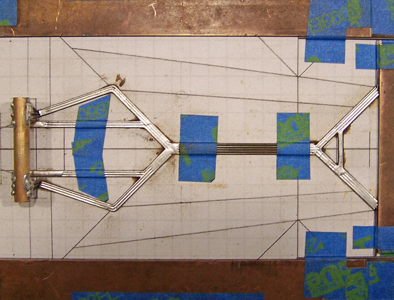
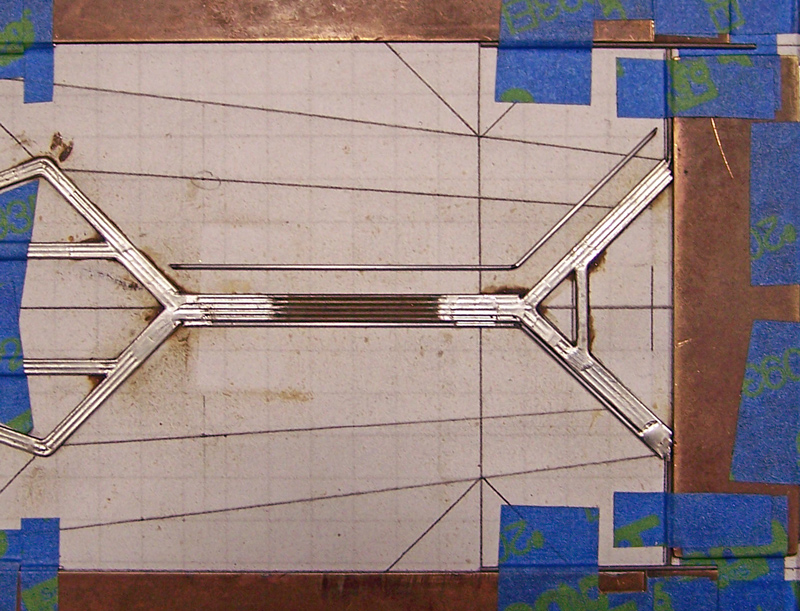
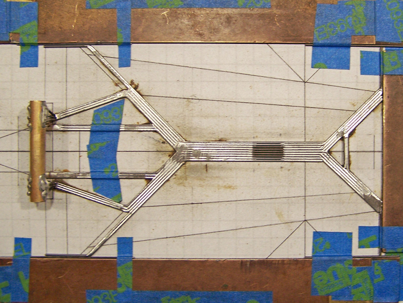
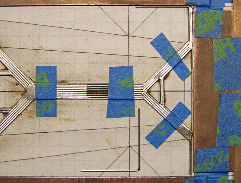
Picture 20: Reference: At this point all wires comprising the main framing, or “main rail” structure, are complete.
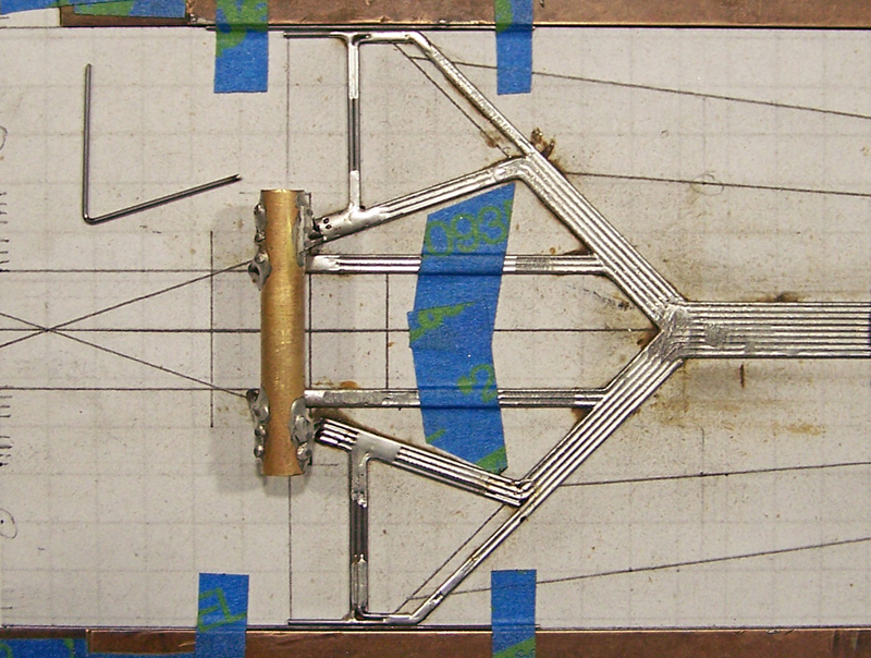
Picture 21: Two 1-bend wires, forming the rear aspect of the lateral rear static pans’ framing; soldered to the third lateral RAX-tube support wire, and tack soldered to the wire in Picture 19.
Picture 22: Two 1-bend wires; soldered to the interior aspects of the lateral rear static pans’ framing wires in Pictures 19 & 21.
Picture 23: Two 1-bend wires; soldered to the interior aspect of the lateral rear static pans’ framing wires in Picture 22 and the third lateral RAX-tube support wire.
Picture 24: Two 1-bend wires; soldered to the interior aspect of the lateral rear static pans’ framing wires in Picture 23 and the fifth center main rail wire.
Picture 25: Two 1-bend wires; soldered to the interior aspects of the lateral rear static pans’ framing wires in Pictures 22 & 24.
Picture 26: The 0.032” spacing wire between the two brass plates defining the chassis front border is removed, with the rear brass plate moved forward. The 0.032” spacing wires forward of the front axle line are removed.
Two 1-bend wires (90-deg), defining the forward and lateral aspects of the front wings; soldered to the forward aspect of the front spanning structure. Excess lengths (lateral extending into wheel-wells, and forward extending into guide-well) to be trimmed later.
Picture 27: Chassis framing so far.
#5

Posted 23 March 2017 - 03:27 PM
1237-Cb3+ Build Sequence, Part 4 of 7
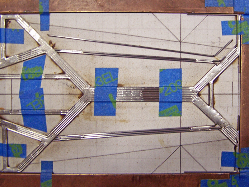
Picture 28: First of four per side buttress rail wires; two 1-bend; positioned along lateral aspect of the buttress rail projection line; soldered to rear-lateral aspect of the fourth center main rail wires only.
Note: The rear ends of all buttress rail wires are not soldered to the chassis rear assembly.
Picture 29: Second buttress rail wires; two 1-bend; soldered to rear-lateral aspect of the fourth center main rail wires and lateral aspect first buttress rail wires only.
Picture 30: Third buttress rail wires; two 1-bend; soldered to lateral aspect of the second buttress rail wires only.
Picture 31: Fourth/final buttress rail wires; two 1-bend; soldered to medial aspect of the first buttress rail wires only.
Picture 32: First of seven per side “side pan” wires; two 1-bend; soldered to rear-lateral aspect of the third buttress rail wires only.
Picture 33: Second side pan wires; two 0-bend; soldered to lateral aspect of the first side pan wires.
Picture 34: Two per side, short 0-bend, spacing wires are solder to the rear aspect of the front spanning structure.
Picture 35: Third side pan wires; two 1-bend; soldered to lateral aspect of the second side pan wires and the spacing wires in Picture 34 (…oops; both wires shown soldered in place…).
Picture 36: Fourth side pan wires (define the rear aspect of the front wheel wells); two 1-bend; soldered to lateral aspect of the third side pan wires.
#6

Posted 23 March 2017 - 03:31 PM
1237-Cb3+ Build Sequence, Part 5 of 7
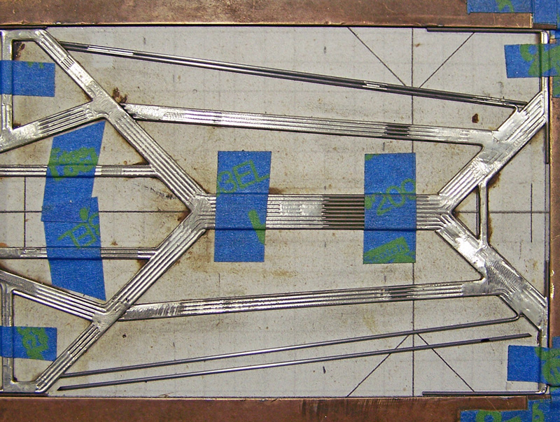
Picture 37: Fifth side pan wires (define the lateral aspect of the “side pans”); two 1-bend; soldered to rear-medial aspect of the fourth side pan wires.
Picture 38: Sixth side pan wires; two 0-bend; soldered to medial aspect of the fifth side pan wires.
Picture 39: Seventh/final side pan wires; two 1-bend; soldered to medial aspect of the fifth and sixth side pan wires, and to the lateral rear end of the third side pan wires.
Picture 40: First of four wires per side completing the front wings (defining the forward aspect of the front wheel wells); two 1-bend; soldered to medial aspect of the wire in Picture 26, and tack soldered to the fourth side pan wire.
Picture 41: Second front wing wires; two 1-bend; soldered to medial aspect of the first side pan wire and lateral aspect of the fourth side pan wire.
Picture 42: Third front wing wires; two 1-bend; soldered to medial aspect of the second side pan wire and rear aspect of the fourth side pan wire.
Picture 43: Fourth/final front wing wires; two 1-bend; soldered to interior aspects of the first and third front wing wires.
Picture 44: Excess wire lengths projecting into front and rear wheel wells trimmed.
This completes the chassis framing. All other components are superstructure.
Picture 45: The 0.010” brass sheet pieces are soldered into the framing, making the lateral rear static pans.
#7

Posted 23 March 2017 - 03:35 PM
1237-Cb3+ Build Sequence, Part 6 of 7
Picture 46: Tubing for buttress rail articulations; two pieces of 3/32” brass round tubing per side are cut, two each 0.20” and 0.25”; one of each length aligned with 0.062” wire; soldered individually to the front of the chassis rear assembly, and to the rear end of the buttress rail (overlapping but not soldered to the chassis rear assembly).
Picture 47: Buttress rail articulation 0.055” wire, passing through both tubes, biased to ride bottom of tubes; soldered to inside-front of forward articulation tube and buttress rail only.
Picture 48: Side pan restrictor box; 1/8” square brass tubing; soldered atop lateral edge of lateral rear static pan framing.
Picture 49: Side pan restrictor wire; 0.055”, biased to set against lower-medial inside corner of side pan restrictor boxes; soldered to rear end of side pans. (Not shown: Rear of the side pan restrictors are cut at an angle for rear tire clearance.)
Picture 50: Guide tongue mount; 0.025” brass plate, cut, tinned and soldered atop center “triangle” of front spanning structure.
Picture 51: Guide tongue tinned and soldered atop 0.025” brass plate.
Picture 52: Guide lateral movement restrictor wires, 0.039”, soldered to top of lateral “45” sides of guide-well.
Picture 53: Rear gear guard; 4-bend (2x in 2 planes) soldered to medial aspects of medial RAX-tube support wires (behind motor bracket face projection line).
Picture 54: Rax-tube spreader; 2-bend; soldered atop gear guard and to top of RAX-tube.
#8

Posted 23 March 2017 - 03:39 PM
1237-Cb3+ Build Sequence, Part 7 of 7
Picture 55: Rear axle tube cut. Motor bracket trimmed, soldered in place. (Alt-view of gear guard and spreader.)
Picture 56: “Soldering rails”, 0.039" wires, used for soldering the motor in place (they also cradle the motor, and add rigidity to the motor box formed by the medial RAX-tube support wires).
Picture 57: Components for adjustable bite bar fabricated: one piece 1/8” square brass tubing with 1/16” hole drilled; two pieces 3/32” square brass tubing; bite bar consists of three pieces of 0.047” wire.
Picture 58: Bite bar installed; 1/8” tube atop central main rail; 3/32” tubes atop buttress rails; bite bar free-floating within tubing.
Bite bar back stop wire, 2-bend 0.055”, soldered to front apex of chassis rear assembly (also stiffens this portion of the framing).
Picture 59: Front and rear spanning front axle uprights, each 4-bend (2x in 2 planes), soldered atop buttress rails.
Picture 60: Body mounting pin tubes (6x, 3 per side; 1/16” brass tubing with 1/16” ID brass collar, atop 0.032” wire) soldered in place. Lead wire holder installed (2x 1/8” round brass tubing, soldered to 0.024” wire; wire soldered to forward-top of bite bar 1/8” square tube).
Done.
- Eddie Fleming and C. J. Bupgoo like this
#9

Posted 23 March 2017 - 03:42 PM
1237-Cb3+ Build Sequence, Epilogue
That wasn’t so bad was it? Maybe? Could’ve been worse, you know…
Some final chassis pics:
If you don’t already know, and you’re really bored, you can follow the entire CMF3 1237-Series in this thread in the Scratchbuilding sub-forum:
CMF3 1237-Series Design and Build Progression
http://slotblog.net/...ld-progression/
If you thought this was overly long, that thread will probably make you want to kill yourself…
Of course, if you have any questions about this chassis or other related builds, and are a real glutton for punishment, please ask here or PM me.
Have fun!
Rick / CMF3
- MarcusPHagen, Eddie Fleming and C. J. Bupgoo like this


