

I was asked to do an AMT 1/25 '68 Camaro Hardbody model kit to slot car conversion by a friend.
Since major body mods like flared fenders and widening of the rockers are planned, keeping everything square and most importantly the wheel wells concentric with the axles is critical.
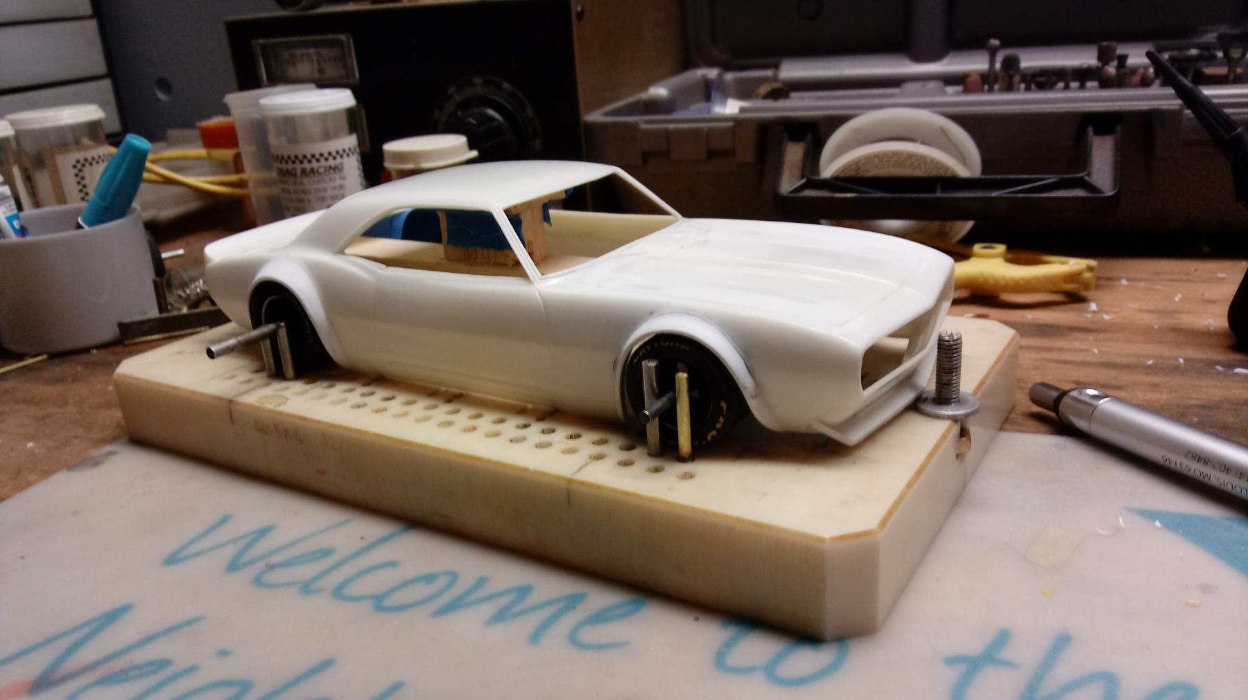
With some fiddling, the Rgeo jig can be set up to fix not only the wheel base but to also provide a jig to hold the body at a fixed point.

With the wheel wells roughed out the body can be placed back onto the jig so front and rear body stops can be installed.
Also installed at this time are four body centering pins that fit flush inside the rocker panels .

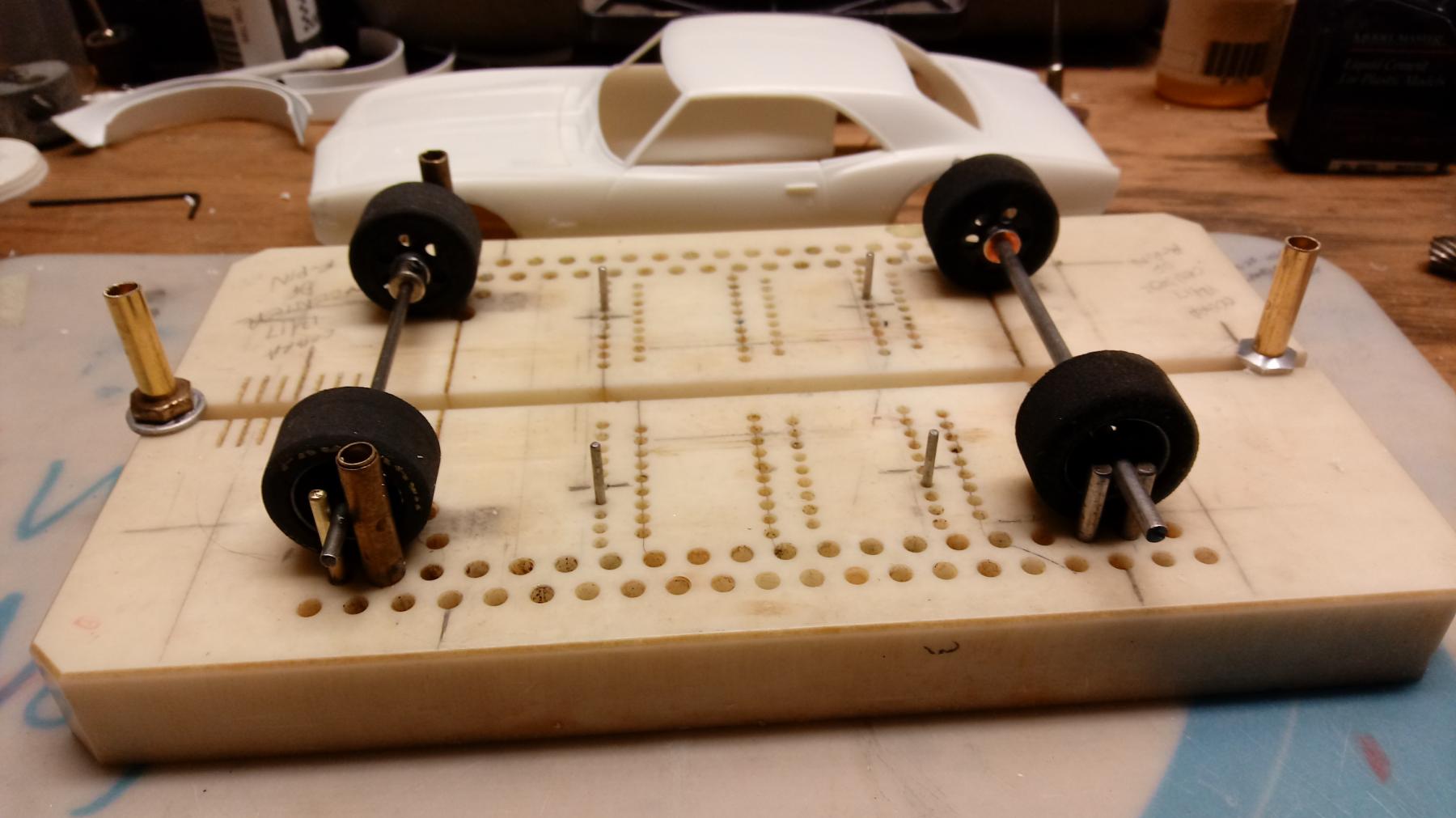
Using this fixture, the body can be returned to a known position when taken off and on over and over again.

R-Geo chassis jig as a Hardbody fixture
#1

-
- Full Member
-

- 197 posts Joined: 02-September 11
Mid-Pack Racer
- Gender:Male
- Location:Maryland Heights, MO
Posted 28 December 2017 - 10:42 PM
- Jencar17, Tim Neja, miko and 1 other like this
#2
-

- Subscriber
-
- 3,424 posts Joined: 05-April 06
Posting Leader
- Gender:Male
- Location:SF Bay Area
Posted 28 December 2017 - 11:11 PM
- Bruce Wayne likes this
Dennis David
#3
-
- Full Member
-
- 197 posts Joined: 02-September 11
Mid-Pack Racer
- Gender:Male
- Location:Maryland Heights, MO
Posted 29 December 2017 - 02:29 PM
In the past I've made custom jigs for each model from a piece of 1 x 4, but since the RGeo jig is so versital, figured why not put it to use.
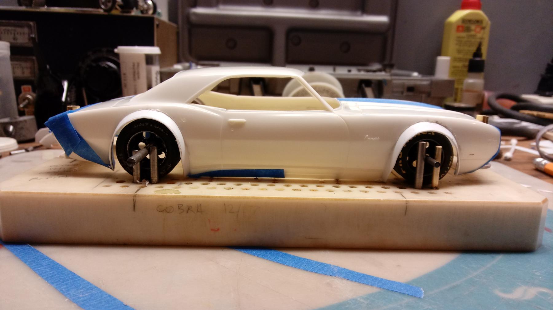
Another project on the bench is this 1/24 Monogram Cobra. Going through similar steps as Camaro, adding flares and widening body.


- Jencar17, miko and garyvmachines like this
#4
-
- Full Member
-
- 197 posts Joined: 02-September 11
Mid-Pack Racer
- Gender:Male
- Location:Maryland Heights, MO
Posted 04 January 2018 - 02:44 PM

Roughing in the first flare using the tire as reference.

Initial flares are attached and "welds" are cooling.
- Jencar17 and miko like this
#5
-

- Full Member
-
- 1,045 posts Joined: 19-February 06
Checkered Flag in Hand
- Gender:Male
- Location:Citizen of the World
Posted 04 January 2018 - 05:00 PM
Necessity, invention, cool.
- Phil Smith and NSwanberg like this
Pete Varlan
60 years a slot racer
#6
-

- Subscriber
-
- 6,846 posts Joined: 11-June 07
Grand Champion Poster
- Gender:Male
- Location:Paso Robles
Posted 04 January 2018 - 06:14 PM
Yes that's a great jig! I build everything from 1/32 to the 1/24 size hard bodies we race at BPR! I haven't found anything it couldn't do!! Hard to beat--lots of options with all the drill patterns Rick has. Very nice jig--I use and recommend!!
Nice build Bruce--you Da Man with those big fender flairs!! 
- Bruce Wayne likes this
#7
-
- Full Member
-
- 197 posts Joined: 02-September 11
Mid-Pack Racer
- Gender:Male
- Location:Maryland Heights, MO
Posted 04 January 2018 - 07:47 PM
Thanks Tim!Nice build Bruce--you Da Man with those big fender flairs!!
Inner flares start as .020" evergreen Sheet Styrene cut into 1"x6" strips, twisted like a ribbon and placed under boiling water for 30-45 sec.
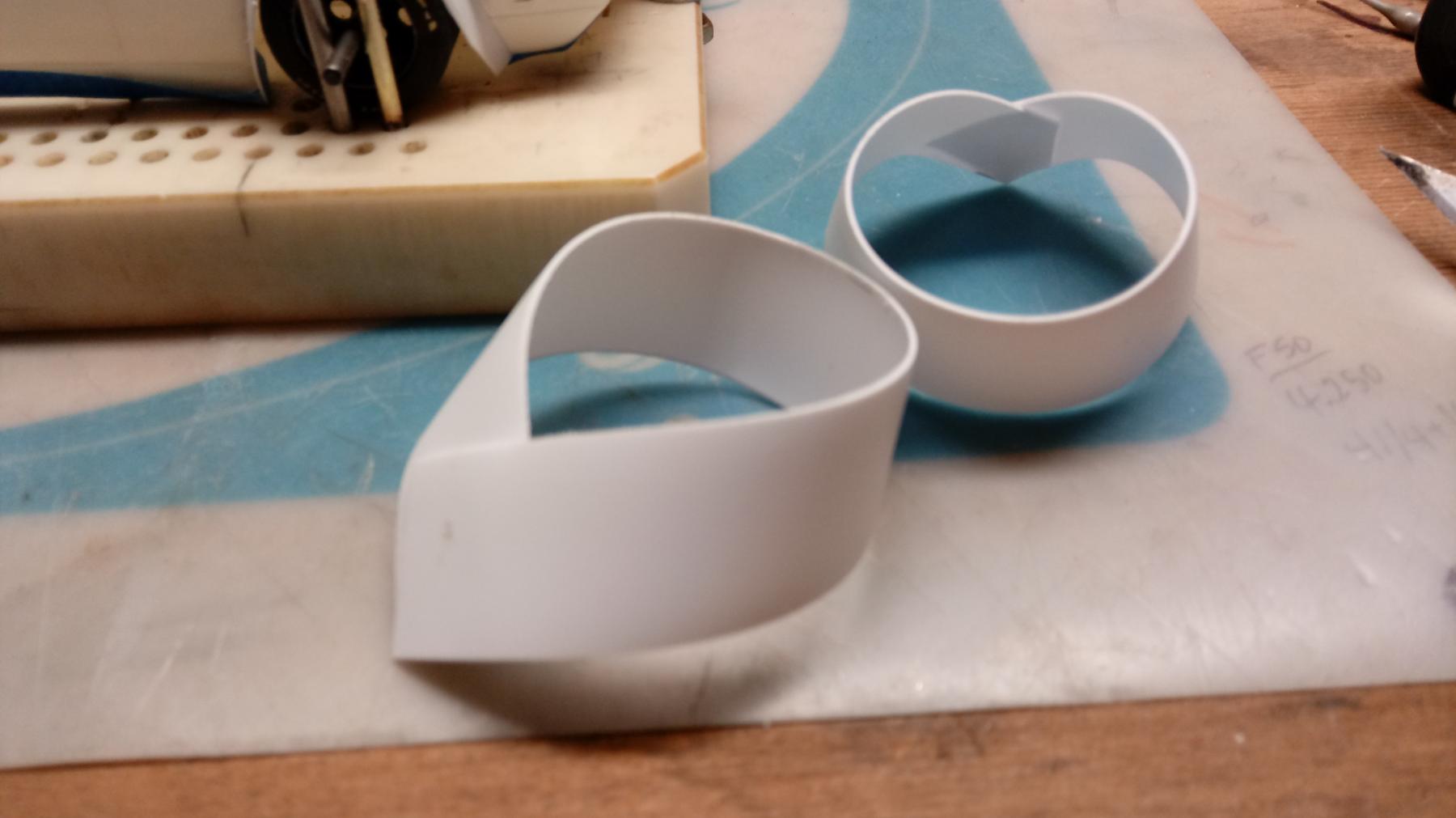
These thinner strips were glued inside the fender lip and serve as a base.
After they cooled, a scribed and laminated layer of .030" was added for .050" total thickness.
This top layer butts the outside of the fender creating a strong "rabbit" joint.
- Jencar17, Tim Neja, Phil Smith and 2 others like this
#8
-
- Full Member
-
- 197 posts Joined: 02-September 11
Mid-Pack Racer
- Gender:Male
- Location:Maryland Heights, MO
Posted 13 February 2018 - 10:41 PM
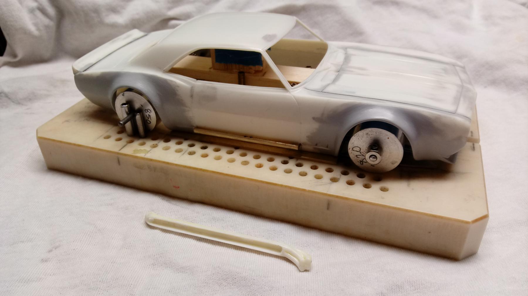
Once a smooth fillet was formed a brush coat of Tamiya gray surface primer showed areas that will need attention.
Also worked up a front chin spoiler using .060 styrene as a base, then added a layer of .030 to the bottom to tighten up the gap.

Happy with how tight the joints came out, minimal filling means less sanding!

First coat of Squadron Products White Putty.

Lots of work has gone into welding the hood shut and tightening up the shut lines.
Model glue, super glue, white putty and surface primer worked with #11 Exacto and hobby saws.

- Jencar17 and miko like this
#9
-
- Full Member
-
- 197 posts Joined: 02-September 11
Mid-Pack Racer
- Gender:Male
- Location:Maryland Heights, MO
Posted 14 February 2018 - 10:03 PM
This of course is where the RGeo jig really shines, as the overall width, wheelbase and track have been set and max guide lead is easy to determine with a known front body overhang.

- Jencar17 and miko like this
#10
-
- Full Member
-
- 197 posts Joined: 02-September 11
Mid-Pack Racer
- Gender:Male
- Location:Maryland Heights, MO
Posted 20 February 2018 - 10:57 PM
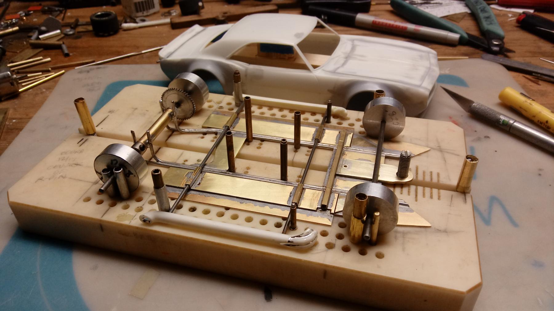
You can also use his body mounting jig if you plan on using pin tubes.
Exactly
With the body and chassis held on a fixed base, the jig makes it simple to keep everything square and perpendicular front to back and in between all during the build process.
In this example, the jig needed some addtional tubing/shimming to obtain up the best pin tube mounting stand location.
Ultimately the pin tubes will also serve as mounts for removalable side pipes, so this is a critical first step.
- Jencar17, Samiam and olescratch like this
#11
-
- Full Member
-
- 197 posts Joined: 02-September 11
Mid-Pack Racer
- Gender:Male
- Location:Maryland Heights, MO
Posted 28 February 2018 - 02:17 PM
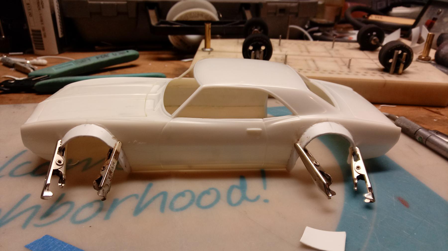
Back of side pipes were hollowed out to fit over tubing.

First test fit. With pipes located now we can cut holes in front fenders for headers to exit.


