Jump to content


Photo

Difalco Genesis HD30 mods


  • Please log in to reply
32 replies to this topic

#1 Slot-Racer

Slot-Racer

    On The Lead Lap

  • Full Member
  • PipPipPipPip
  • 267 posts
  • Joined: 01-December 17
  • Gender:Male
  • Location:CA

Posted 22 August 2018 - 12:45 PM

I wanted to share this mod as it's easy to do and it only cost around $15.00


Controller: Difalco Genesis HD 30 Kit to upgrade Parmat Turbo. https://e-slotcar.co...-module-dd-275/


I actually built this from scratch although when you talk to Difalco they expect you to do it off an existing Parma as an upgrade, but I don't see a point of that if you just buy the Parma frame and handle and trigger. It's way more cost effective and you can do a cleaner install.


Two 40mm Fans


$10.00 Fans: https://www.amazon.c...aidmax 40mm fan


Fans.jpg


I ran the controller and noticed it got hot, so wanted to add a fan. Of all the sizes out there, 40mm was the perfect size so I added two 40mm, 12v fans. They are wired in parallel and mounted in a push rather than pull configuration on top of the heatsink and over the power transistor. What this means is that instead of pulling the heat away from transistor/heat sinks, the fans will be pushing colder ambient air on top of the transistor and heat sinks. You can do it either way, but I felt a push configuration in this case is much more effective due to the proximity of the fans to the transistor and heatsinks.


There is plenty of cooling CFM at 6000 RPM and pretty quiet due to the sealed bearing in the fans. I tested them at 13.5v also and they run like a champ, even at 14v! They were easy to install and can be removed for replacement at any time. They way they were installed is with a thick silicone tube that is pressed into the heatsink and a plastic screw were from the top screwed down into the silicone tube. This makes it all removable and also makes it a tight fit without hurting the heatsinks using sheet metal screws or other. The wiring is easy, take both the positive lines of each fan and connect them together and take both wires of the negative fan wires and connect them together. So the two positives and the two negatives of each fan are connected to each other, negative to negative together and the positive to positive together, this is a parallel connection. The reason for a parallel connection is so that each fan runs at max RPM and voltage.


Then you simply take the positive lines of the fans and connect them to your white power on your controller which is the + (positive) and the negative lines from the fans and connect it to the - (negative) on your controller (the same lines that you connect to the track in case you are confused which lines these are). Once you connect the clips to the terminals on the track, the fans will turn on and always be on. I was thinking to add an On/Off switch but decided there's no point. 


2 Fans.jpg


Volt Meter


$4.00 Volt meter: https://www.amazon.c...e?ie=UTF8&psc=1


51hlt-ERAUL._SL1001_.jpg


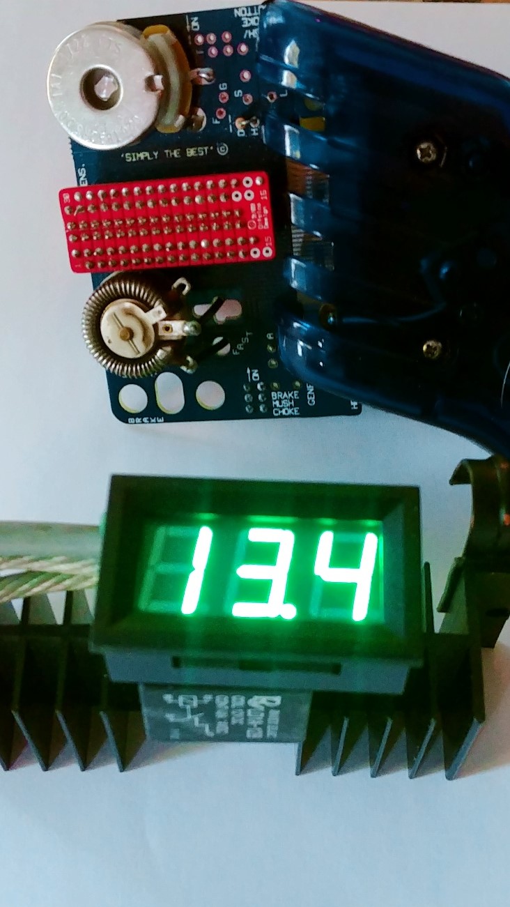
When I ran the controller I'm glad I had some indicator on the controller so I know what's going on while running it and the cars. The voltmeter is a good idea for quite a few reasons. One is that the controller itself has no ON/OFF indication or a light or a switch etc. I don't like anything electronic that does not have an indicator of an on/off state as it always leaves you guessing is the device on, is there power on the track, is the car connected, is there a dead spot on the track, is the motor lost a connection etc. It's also handy to know that the controller has not lost connection itself and helps to know when the car has lost connection on the track (for different reasons) as when it does the voltage display turns off is any of these cases mentioned. Of course it's most obvious that it also gives you the lane voltage so when they state they have the track set to 13.2v it's what it really is as for racing they crank it up. This is a super handy mod even if you don't put a volt meter, even a $2.00 LED light would be a great idea. Why an inexpensive device is not already included stumps me. If you want to add in a LED light, ( I was thinking that at first) there are already holes on the top left of the controller you can use to mount it and wire it the same way as the volt meter. 


The voltmeter is rated 0-30v DC so you can never fry it, and it's just the right size to fit inside the Parma handle away from any other moving parts and is protected. I shaved the mounting holes on both sides of the board on the volt meter, and I added a piece of foam on the top (to fit tight) and on the back of the board to prevent a short as the circuit board is exposed and sitting on top of the Parma aluminum frame. I positioned it next to the trigger, it's a perfect fit, it never moves around or anything. The way it's wired is to take the volt meter's red wire and connect it to your white power on your controller which is the + (positive) and the black wire from the volt meter and connect it to the - (negative) on your controller (the same lines that you connect to the track in case you are confused which lines these are). Once you connect the clips to the terminals on the track the volt meter will turn on giving you the voltage. 


Volt.jpg


I really enjoyed doing this mod to my Difalco Genesis HD30 and now enjoy it even more!


  • tonyp, Half Fast, glueside and 3 others like this
Mario Damis


#2 TG Racing

TG Racing

    On The Lead Lap

  • Full Member
  • PipPipPipPip
  • 468 posts
  • Joined: 11-December 11
  • Gender:Male
  • Location:Kettering, OH

Posted 22 August 2018 - 02:38 PM

What type of cars do you run?


Thom Greene

#3 Slot-Racer

Slot-Racer

    On The Lead Lap

  • Full Member
  • PipPipPipPip
  • 267 posts
  • Joined: 01-December 17
  • Gender:Male
  • Location:CA

Posted 22 August 2018 - 03:01 PM

I have X-12's to Group F to G20 and one ProSlot Infinity open motors.


  • TG Racing likes this
Mario Damis

#4 The Sawdust Man

The Sawdust Man

    Mid-Pack Racer

  • Full Member
  • PipPipPip
  • 140 posts
  • Joined: 24-October 16
  • Gender:Male
  • Location:Canton, MI

Posted 22 August 2018 - 03:41 PM

Very nice! Where did you get the silicone tube?


  • Slot-Racer likes this
Robert Manzitti

#5 Slot-Racer

Slot-Racer

    On The Lead Lap

  • Full Member
  • PipPipPipPip
  • 267 posts
  • Joined: 01-December 17
  • Gender:Male
  • Location:CA

Posted 22 August 2018 - 03:45 PM

Very nice! Where did you get the silicone tube?


Thank you. :D  The silicone tube is from Tower Hobbies used in RC boats for water cooling. You can use anything that you can find that fits.


  • The Sawdust Man likes this
Mario Damis

#6 Half Fast

Half Fast

    Keeper Of Odd Knowledge

  • Subscriber
  • PipPipPipPipPipPipPip
  • 2,628 posts
  • Joined: 02-May 07
  • Gender:Male
  • Location:NYC, Long Island

Posted 22 August 2018 - 07:11 PM

Good job!


I take it you have to run wires from the volt meter down to the transistor module as there is no proper connection in the handle itself.


Cheers


Bill Botjer

Faster then, wiser now.

The most dangerous form of ignorance is not knowing that you don't know anything!

Never attribute to malice that which is adequately explained by stupidity


#7 Slot-Racer

Slot-Racer

    On The Lead Lap

  • Full Member
  • PipPipPipPip
  • 267 posts
  • Joined: 01-December 17
  • Gender:Male
  • Location:CA

Posted 23 August 2018 - 10:00 AM

Good job!


I take it you have to run wires from the volt meter down to the transistor module as there is no proper connection in the handle itself.


Cheers


Correct, somewhat. I ran one tiny red wire directly to the positive (+) white wire on the transistor module board which is the same white wire that goes to the clip you would attach to the track to get power. You could also use the white wire that is off the wiper (white) wire but I preferred to keep them separated for troubleshooting purposes down the road. 


The black you can connect to the black that goes to the break stop contact as that is negative (-), and this is in the handle of course.


My Pic II.jpg


  • Half Fast likes this
Mario Damis

#8 Phil Beukema

Phil Beukema

    On The Lead Lap

  • Full Member
  • PipPipPipPip
  • 285 posts
  • Joined: 02-May 18
  • Gender:Male
  • Location:San Diego

Posted 23 August 2018 - 01:00 PM

I would prefer to attach the Volt Meter to the heat sink area.


Would it be voltmeter Red to controller White and volt Meter Black to controller Red?


  • Ramcatlarry and Tim Wood like this
"Line 'em up!"

#9 Slot-Racer

Slot-Racer

    On The Lead Lap

  • Full Member
  • PipPipPipPip
  • 267 posts
  • Joined: 01-December 17
  • Gender:Male
  • Location:CA

Posted 23 August 2018 - 01:07 PM

I would prefer to attach the Volt Meter to the heat sink area.


Would it be voltmeter Red to controller White and volt Meter Black to controller Red?


Voltmeter red (+) goes to white line on Difalco, I know it's tempting to connect to red but that is not the true positive (+) white is. Red it actually the brake. Then connect volt meter wire black goes to black (-) on Difalco which is actually true negative (-). I was confused also at first thinking red is (+) and white is something else like brake and black was negative.


Well on these controller's it's not. Connect the way I mentioned, then take a 9v battery and connect your controller alligator clips to it, alligator white to positive (+) and alligator black to negative (-) and you will see the volt meter turn on and give 9v. When you pull the trigger it will go lower and lower in voltage as it's going through the resistor network and turn off. That means you have it wired and working right.


When you connect your controller to the race track, adding in the Red (brake) then the volt meter it will always be powered and when power is lost or etc (all things I mentioned above) it will turn off. Below diagrams should give more help in "seeing" how a controller it works. Hope that helps. 


WIRING.jpg


Snap94.jpg


Mario Damis

#10 Phil Beukema

Phil Beukema

    On The Lead Lap

  • Full Member
  • PipPipPipPip
  • 285 posts
  • Joined: 02-May 18
  • Gender:Male
  • Location:San Diego

Posted 23 August 2018 - 02:04 PM

Perfect, thanks


  • Slot-Racer likes this
"Line 'em up!"

#11 Slot-Racer

Slot-Racer

    On The Lead Lap

  • Full Member
  • PipPipPipPip
  • 267 posts
  • Joined: 01-December 17
  • Gender:Male
  • Location:CA

Posted 23 August 2018 - 02:57 PM

Perfect, thanks


Welcome. Lets us know what yours looks like?


Mario Damis

#12 Phil Beukema

Phil Beukema

    On The Lead Lap

  • Full Member
  • PipPipPipPip
  • 285 posts
  • Joined: 02-May 18
  • Gender:Male
  • Location:San Diego

Posted 23 August 2018 - 04:33 PM

I'll post a picture. It's a  week away from Amazon.


  • Slot-Racer likes this
"Line 'em up!"

#13 The Groove

The Groove

    On The Lead Lap

  • Full Member
  • PipPipPipPip
  • 328 posts
  • Joined: 14-December 08
  • Gender:Male
  • Location:MI

Posted 24 August 2018 - 11:06 AM

Let me know if that volt meter holds up as I have blow everyone I have tried it may take a day or two but the similar ones I have got have blown


Rich Attee, THE GROOVE-PSC race team

PRECISION SLOT CARS - BUILT TO WIN
Check out my track at Precision Slot Cars

#14 Slot-Racer

Slot-Racer

    On The Lead Lap

  • Full Member
  • PipPipPipPip
  • 267 posts
  • Joined: 01-December 17
  • Gender:Male
  • Location:CA

Posted 24 August 2018 - 11:37 AM

Let me know if that volt meter holds up as I have blow everyone I have tried it may take a day or two but the similar ones I have got have blown


I've run it for an hour, load and no load and no issues. It's voltage rating is to 30v. Can't see how you can blow it? The way I am wiring it is to tap off the power lines only (parallel) not in series with it. If you are connecting it in a way (series) that the car or track voltage is going though it that would be one possible way I can think of being able to blow it amperage wise as there is no amp rating on it that I see. If there is a fear to blow it, I guess you can always add in a diode or fuse to protect it?  :)


Mario Damis

#15 old & gray

old & gray

    Checkered Flag in Hand

  • Full Member
  • PipPipPipPipPipPip
  • 1,207 posts
  • Joined: 15-April 11
  • Gender:Male
  • Location:CT

Posted 24 August 2018 - 02:09 PM

Volt meters generally have a very high resistance and draw very little current when wired in parallel. 

It wired in series, the volt meter will pass a very small current (mA) and a motor will barely turn over.


  • Slot-Racer likes this
Bob Schlain

#16 Phil Beukema

Phil Beukema

    On The Lead Lap

  • Full Member
  • PipPipPipPip
  • 285 posts
  • Joined: 02-May 18
  • Gender:Male
  • Location:San Diego

Posted 24 August 2018 - 05:42 PM

^^^ Good to know!


"Line 'em up!"

#17 Slot-Racer

Slot-Racer

    On The Lead Lap

  • Full Member
  • PipPipPipPip
  • 267 posts
  • Joined: 01-December 17
  • Gender:Male
  • Location:CA

Posted 24 August 2018 - 06:04 PM

The only thing I can think of that you would ever really put in series to "measure" (as a measuring device)  would be an amp meter.


Mario Damis

#18 SpeedyNH

SpeedyNH

    Old Engineer

  • Full Member
  • PipPipPipPipPip
  • 760 posts
  • Joined: 18-July 15
  • Gender:Male
  • Location:Cow Hampshire

Posted 24 August 2018 - 06:12 PM

I've used quite a few of the new self-powered, 2-wire digital LED Voltmeter modules and have found them extremely useful and pretty much damage- and misuse-resistant.


not sure if this is the case above, but the older style DVM modules with separate power and measuring connections cannot have them wired in common or the unit will be destroyed. I used to make simple little isolated power supplies out of capacitively-coupled 555 IC oscillators for the LCD variety, as that type doesn't require much supply current. 


I'm pretty impressed with the new ones. heck, we used to even have to put in our own precision divider string as the module was 0-1.999V and you had to hard-wire the decimal point as well; these jobbies even auto-float when crossing from one to two-digits before the decimal! 

seriously cool, and one cannot beat the price. think that I've installed about nine of them so far.

speedy


  • Slot-Racer likes this

Steve Lang


#19 Slot-Racer

Slot-Racer

    On The Lead Lap

  • Full Member
  • PipPipPipPip
  • 267 posts
  • Joined: 01-December 17
  • Gender:Male
  • Location:CA

Posted 24 August 2018 - 06:16 PM

I've used quite a few of the new self-powered, 2-wire digital LED Voltmeter modules and have found them extremely useful and pretty much damage- and misuse-resistant.


not sure if this is the case above, but the older style DVM modules with separate power and measuring connections cannot have them wired in common or the unit will be destroyed. I used to make simple little isolated power supplies out of capacitively-coupled 555 IC oscillators for the LCD variety, as that type doesn't require much supply current. 


I'm pretty impressed with the new ones. heck, we used to even have to put in our own precision divider string as the module was 0-1.999V and you had to hard-wire the decimal point as well; these jobbies even auto-float when crossing from one to two-digits before the decimal! 

seriously cool, and one cannot beat the price. think that I've installed about nine of them so far.

speedy


Yes this one is a good quality. The ONLY thing I was bummed out about was that the display color is orange and I prefer green! These may also be found on Ebay too but I did get mine off amazon. 


Mario Damis

#20 SpeedyNH

SpeedyNH

    Old Engineer

  • Full Member
  • PipPipPipPipPip
  • 760 posts
  • Joined: 18-July 15
  • Gender:Male
  • Location:Cow Hampshire

Posted 24 August 2018 - 07:29 PM

well, I have mostly red and a couple yellow and green. I haven't seen orange, but it's been a few years since I've ordered any.

I would have loved orange! I work with military aircraft, and that's my install color. but that's just me. lol

I got some of mine from an electronic surplus dealer, Marlin P. Jones.


Steve Lang


#21 Phil Beukema

Phil Beukema

    On The Lead Lap

  • Full Member
  • PipPipPipPip
  • 285 posts
  • Joined: 02-May 18
  • Gender:Male
  • Location:San Diego

Posted 26 August 2018 - 11:38 AM

0825181844_resized.jpg


  • Tim Wood likes this
"Line 'em up!"

#22 SpeedyNH

SpeedyNH

    Old Engineer

  • Full Member
  • PipPipPipPipPip
  • 760 posts
  • Joined: 18-July 15
  • Gender:Male
  • Location:Cow Hampshire

Posted 26 August 2018 - 12:29 PM

nice!


Steve Lang


#23 Slot-Racer

Slot-Racer

    On The Lead Lap

  • Full Member
  • PipPipPipPip
  • 267 posts
  • Joined: 01-December 17
  • Gender:Male
  • Location:CA

Posted 27 August 2018 - 01:46 PM

Ok! So I ran one of my wing babies and while the volt meter has zero issues, the fans are in question. One stopped working. I will go to a different type and size.


Here is video how the car ran though: 


I guess it's setup ok.  :)


Mario Damis

#24 Phil Beukema

Phil Beukema

    On The Lead Lap

  • Full Member
  • PipPipPipPip
  • 285 posts
  • Joined: 02-May 18
  • Gender:Male
  • Location:San Diego

Posted 29 August 2018 - 01:55 PM

As predicted by Rich, I'll have to spend more an $5 on a volt meter. That one lasted 20 seconds (maybe my car was too fast) :laugh2:


  • Tim Wood likes this
"Line 'em up!"

#25 Roy Lievanos

Roy Lievanos

    On The Lead Lap

  • Full Member
  • PipPipPipPip
  • 273 posts
  • Joined: 27-August 16
  • Gender:Male
  • Location:Santa Ana, CA

Posted 29 August 2018 - 02:56 PM

Great info. I have been wanting to install a volt meter on my controller but didn't know where to start. Gona give it a try on a DR 40.
Thanks.
  • Slot-Racer likes this

2024 Western States TMO Champion
2023 Barnburner OMB TQ
2022 Western States HB12 Champion
2021 NASRA OMB National Champion
2021 NASRA OMB National Lap World Record

2017 USRA Div 1 Nats “F” class National Champion
2017 Western States "Retro Hawk F class" Champion
Thank you, John and Dee Hale - Santa Ana Raceway circa 1962


Electric Dreams Online Shop