

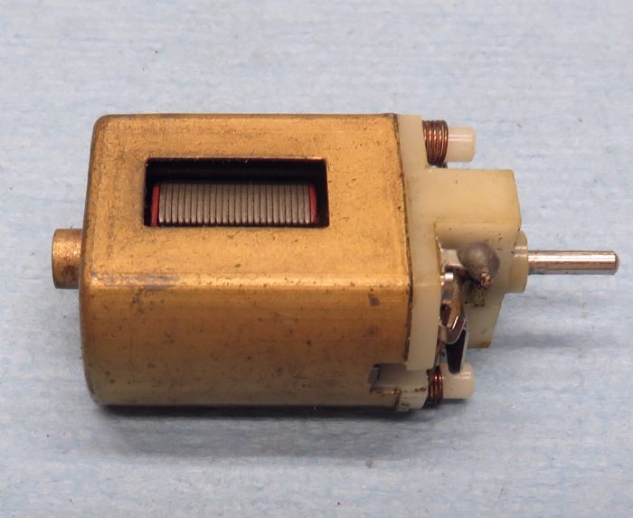
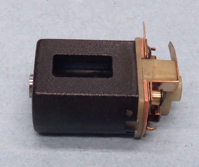
I've probably done 4, 5, maybe 6 of these, and they result in a pretty cool vintage-type motor, and one with some serious horsepower potential. The source for the can, and what really drives the rest of the build is the good ol' Russkit "22" and/or identical types marketed by others. Not having the better end bell of the subsequent "23", the "22" is far less desirable, and you can still find examples in good-to-very-good condition:
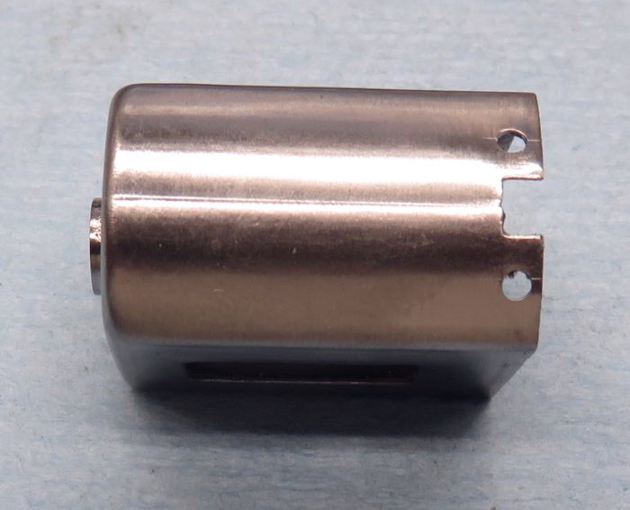
Not having the better end bell, the arm and end bell get either tossed or put aside. The end bell, minus the hardware CAN be used for projects where you'll be doing major modifications that are probably not at all "like" what anyone probably did back then, and the end bell bushing at least can be saved for other end bells where the bushing needs replacing. For this type build, all I really need is the basic can.
So the can blind-bushing gets removed (of course!), the magnets again, either put aside or tossed. Next thing is to scribe a line all the way around the can at the midpoint. This is an easy thing to do using basic carpentry-type techniques  . Set the can on a hard/flat surface, and then place pieces of metal (*I use brass plate like you'd use for chassis pans) on top of each other until you think you're at...or near the midpoint by just eye-balling things. It doesn't matter if you're a little short or tall. Scribe a line all the way around the can with the back edge of an X-Acto blade, ***Then flip the can over and do it all again. If the two lines aren't exactly on top of each other, the center line of the can is right in between the two. Now you have your cut line.
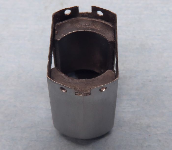
You don't need anything fancy-shmancy to make the cut, just a "Dremel" type motorized hand tool and a thin cutoff disc. Carefully make the cuts on the two curved sides, and then finish on the flat bushing end, being careful not to pinch the can as the cut is made which will instantly demo the disc. ***Even if the cut wanders a bit, the two sides will be going right back together and should fit almost perfectly. What I do however is to play the two cut halves against some fine sandpaper stuck to my work-surface until I can see that all of the cut has been sanded, which doesn't take long at all. Afterwards, the two sides get soldered together, and you should have a nice-looking joint all the way around.
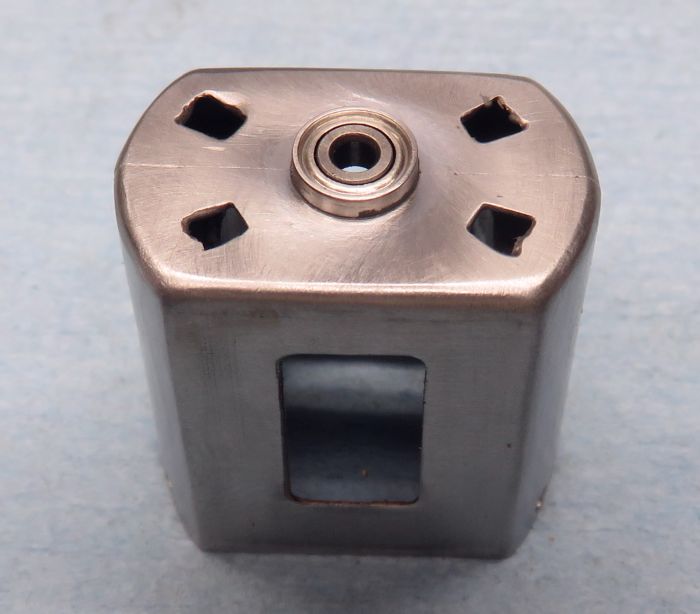
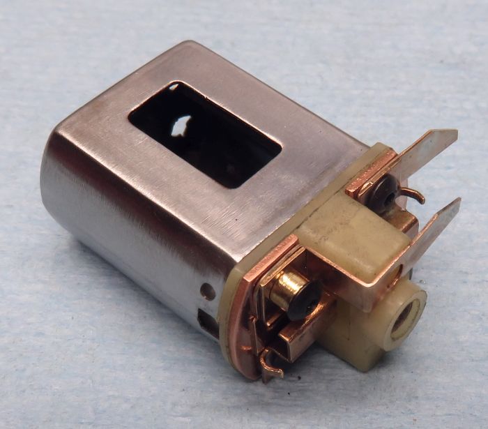
On the bearing end of the can, you'll wind up with a small "eye-shaped" hole instead of the original round hole because you've shortened the height of the can by the width of the thin cutoff disc cut or "kerf". You can now hold the can being careful not to break the very thing solder joint (*I don't clean up any extra solder until AFTER doing this step because the can joint will only get weaker after doing that), and use a taper-ream to open up the hole to either 5mm or 6mm. The ream will follow even the not-round hole perfectly, and leave you with a lovely round hole. Now you can either solder or epoxy-in the bearing. I epoxy these in because I want to avoid messing up the solder joint...besides, epoxy is probably less destructive to the bearing than acid and solder. Again you should wind up with a nice joint, and the bearing itself works to reinforce the back end of the can...kind of a "win-win" kinda thing:

A favorite motor project revisited
#1

-
- Subscriber
-

- 11,198 posts Joined: 20-August 07
OCD Rewinder
- Gender:Male
- Location:NY
Posted 05 October 2018 - 07:25 AM
- Jencar17, Tex, olescratch and 2 others like this
#2
-
- Subscriber
-
- 11,198 posts Joined: 20-August 07
OCD Rewinder
- Gender:Male
- Location:NY
Posted 05 October 2018 - 07:41 AM
With the can this far, I can now hold it carefully again and locate/drill the end bell mounting holes (shown in the previous pictures). Now it's time for magnets and guess what?...C-can magnets will fit very nicely! I chose a set of the older, but very strong, ones for this and looked at how to shim them to get a workable "hole" without going to a large diameter armature. Turns out an old thick Champion shim cut-up will do nicely. I first epoxied the shims to the magnets carefully and set them aside. Once cured, I epoxied the magnets and shims into the can using a slug wrapped in masking tape and got a pretty great .530" hole.
***At this point, you need to figure an end bell and you have two choices, because a C can end bell will fit about perfectly, or a B end bell with some tweaking. I chose a "B" because I had one, but added some "B" and "C" hardware. It's still all-vintage, and could easily have been done back in the day., and probably was, because people tried everything you could think of, and some stuff you wouldn't think of. 
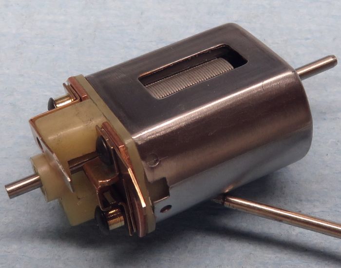
Now you have something very much like a motor made using the two-piece low-profile can kits, and one that's probably significantly lighter to boot. It's certainly lighter than even the milled-down B can motors, and ready for some serious horsepower in the shape of an armature. I'll probably add some can mounting holes, even though the can metal of these old Mabuchis is much thinner than the Mura and similar cans. At the very least, they would provide a way to temporarily mount and locate the motor while soldering bracing to get things solid. Of course, the end bell has holes too, but I don't think (?) those were used much, or at all.
As a last check to make sure alignment is groovy , I stuck an arm blank just over .518" diameter into the .530 hole, it's tight and doesn't rub anywhere. No magnet honing here, and a light OD grind along with balancing will make for a suitably tight setup. This will be a deadly motor, and it started out as an old Mabuchi. I like that!
- Pablo, Jencar17, Tex and 5 others like this
#3
-

- Subscriber
-
- 1,856 posts Joined: 26-October 07
Checkered Flag in Hand
- Gender:Male
- Location:Lexington. SC
Posted 05 October 2018 - 06:30 PM
I'm sure you've covered this before but why did you "split" the can instead of just leaving it a solid drawn can? To thin it the thickness of the dremel disc? Thanks.....
Don
Don Weaver
A slot car racer who never grew up!
The supply of government exceeds demand.
L.H. Lapham
If the brain-eating amoeba invades Washington
it will starve to death...
#4
-
- Subscriber
-
- 11,198 posts Joined: 20-August 07
OCD Rewinder
- Gender:Male
- Location:NY
Posted 05 October 2018 - 07:38 PM
I'm sure you've covered this before but why did you "split" the can instead of just leaving it a solid drawn can? To thin it the thickness of the dremel disc? Thanks.....
Don
Really two reasons Don. One is that, once the height is shortened by around the width of a thin cutoff disc kerf, a whole world of better magnets and end bells gets opened-up for the Mabuchi. Of course, you can use modern D motor magnets today, which is kind of a "cheat", but those are mostly for large diameter arms, as they result in a .590"-ish hole. There are also much better modern end bells, but those would not just be a cheat, but don't even look like the old stuff...there goes the illusion. ***To me, this build should be fine for a vintage car...because it IS all vintage, and could have been done, it may well have been done. The resulting motor is lighter by a good amount than a Green Can, and won't get as hot as a "B" motor might.
The second is because there were two-piece can kits very much like this (*I think by Associated, maybe some others). These were sold as something like "low-profile pro" or some goofy thing like that. Someone had gifted me one of those some years ago, and I did the build...it was a very cool thing. So this is my "take" on those.
---------------------------------
Besides the above, in today's world, there are very few good FT16D motors around, but there are still a fair amount of Russkit "22" types. This is a good way to make use of those cans at least, and wind up with a cool motor...and one that can be very fast, even by today's standards. Oh yeah and...it's just a fun and somewhat challenging project to boot. Like scratch building a chassis, except scratchbuilding a motor instead. There's also the fact that such a motor is unique. Even the vintage guys most likely won't have one of these in their collection, and that right there alone is good reason.
There might be more reasons I'm not thinking of right now, but the above ones are a pretty good list!
- MarcusPHagen, Pablo and olescratch like this
#5
-

- Full Member
-
- 14,760 posts Joined: 02-August 07
Age scrubs away speed!
- Gender:Male
- Location:New Boston, NH
Posted 05 October 2018 - 08:05 PM
I've previously read that Bob Green cut down 16D motors this way before there were B-cans & C-cans. He would have had to cut down magnets to fit them too.
- havlicek likes this
I intend to live forever! So far, so good.

#6
-
- Subscriber
-
- 11,198 posts Joined: 20-August 07
OCD Rewinder
- Gender:Male
- Location:NY
Posted 06 October 2018 - 04:34 AM
I've previously read that Bob Green cut down 16D motors this way before there were B-cans & C-cans. He would have had to cut down magnets to fit them too.
I thought he did something like this as test mules before having the cans and magnets produced. He would have had to come up with end bells too. It would be cool if any of those experiments survived.
#8
-
- Full Member
-
- 14,760 posts Joined: 02-August 07
Age scrubs away speed!
- Gender:Male
- Location:New Boston, NH
Posted 06 October 2018 - 09:05 AM
If anyone had the Bob Green motors mentioned in post #5, it would be the LASCM.
I intend to live forever! So far, so good.
#9
-
- Subscriber
-
- 11,198 posts Joined: 20-August 07
OCD Rewinder
- Gender:Male
- Location:NY
Posted 06 October 2018 - 12:10 PM
If anyone had the Bob Green motors mentioned in post #5, it would be the LASCM.
Probably, but I don't remember seeing an actual motor...maybe just pictures in an old article. It's been a while.
#10
-
- Full Member
-
- 14,760 posts Joined: 02-August 07
Age scrubs away speed!
- Gender:Male
- Location:New Boston, NH
Posted 06 October 2018 - 12:22 PM
PDL has mentioned them before, so he should know if any still exist & where they are. Did you make the thick copper pieces (heat sinks) that sit behind the backing plates on this motor of yours?
I intend to live forever! So far, so good.
#11
-
- Subscriber
-
- 11,198 posts Joined: 20-August 07
OCD Rewinder
- Gender:Male
- Location:NY
Posted 06 October 2018 - 04:29 PM
PDL has mentioned them before, so he should know if any still exist & where they are. Did you make the thick copper pieces (heat sinks) that sit behind the backing plates on this motor of yours?
Those were gifted to me...maybe by Rick T. (?) He's about the only person I can think of that would have such things. They needed a bunch of flattening before installing, as the "top" sides were concave from punching the holes. I actually installed a set of the Mura heatsinks under those for more clearance.


