Before I go into detail on how I built my "Tire Groomer (TG)", I would like to take the opportunity to thank our illustrious "Hot Rod Motor Builder" Sir John Havlicek, for bringing up the topic of "the builder who wants more".
http://slotblog.net/...who-wants-more/
I had been looking at that particular "Bead Drill/lathe" on eBay, for a long while, along with other similar devices for no apparent reason at the time.
I just thought it was very KOOL looking device - miniature at that!!!!
I was thinking "what could I use this for?!"
Then, it just happened, my Version 1 - Tire Groomer, was no longer working effectively and needed to come up with a replacement.
That's when I read John's thread again, that I decided to purchase the device.
I purchased the lathe on eBay from a California based seller.
For the (very affordable) price, I was not going to expect a "precision" device but hoped I could get to work for my need.
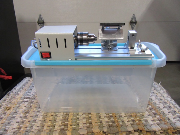
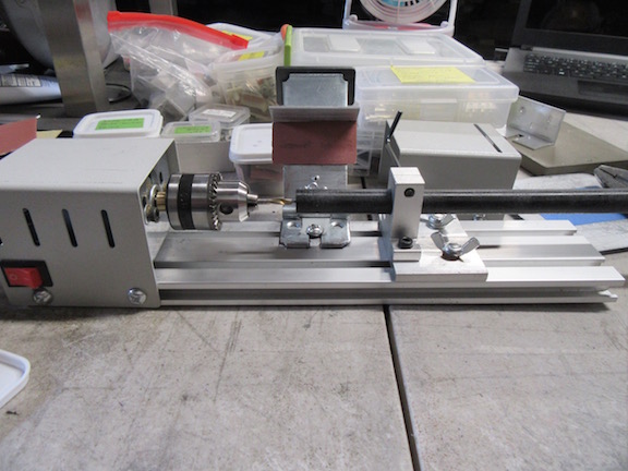
Here it is as it arrived:

This device has the 110V adapter, so I could plug it into the wall - I noticed some sellers offer just the 12V version.
Placed on the table for inspection.

Tailstock alignment looks good to me!

It took me a day to "imagineer" the design, but basically, since my Version 1 TG, worked well for my tire grooming needs, I decided to apply the similar design to V2.
My requirement for this project, was to be able to put this TG together using only basic hand tools and parts bought off the shelf at the local home improvement/hardware retailers.
Tools I used:
- Saw: to cut aluminum angle
- Cordless hand drill
- 1/8" drill bit
- 1/4" drill bit
- Rivet Gun
- Phillips screwdriver
- 2.5mm hex wrench
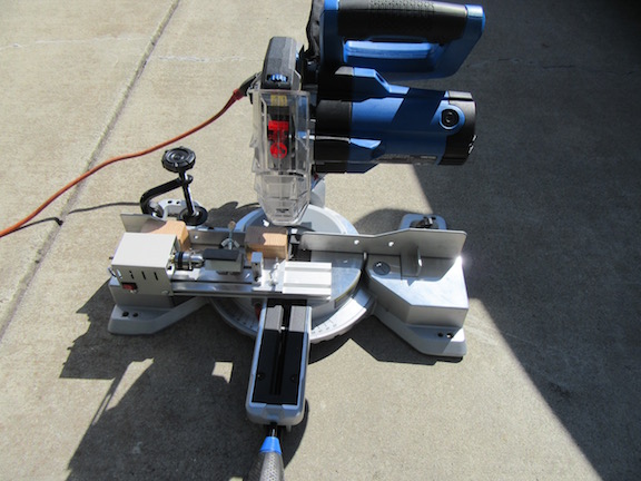
- Mini Chop Saw
- 4" wide vise
- Hand files: rat tail/flat file
Parts:
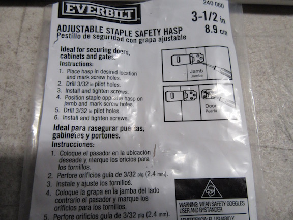
- 3-1/2" Safety Hasp -- basically a door latch that accommodates a padlock
- 1/2" OD Acetal (Delrin) Rod
- 1/4-20 Thumb Screw: 2" long
- 1/4-20 Wing nut
- 1/4-20 Tee Nut
- 3/32" Aluminum blind pop rivets
- Angle aluminum: 1"x1" leg -- 2" long piece
- 1/8"rod x 3-1/2" long
So, I first removed the live center piece along with the bearings from the tailstock - the bearings push out easily!

I neglected to take a photo when I initially center drilled the 1/2" OD acetal/delrin rod, so I took photos of how I accomplished that task.
I installed a 1/8" drill bit into the chuck, then slid the 1/2" rod thru the tailstock.
You must be sure that the live center is accurate because when you loosen the tailstock to move it closer to the drill bit, it will become misaligned.
It took a few passes because the tailstock I.D. is a micro-millimeter larger than 1/2" thus having too much play, so it was remedied by tightening the tailstock lock screw to where there was virtually no play, yet I could still slide the rod into the drill bit.
Drill bit installed and Acetal rod in place.
Tightening the tailstock to eliminate play using a 2.5mm hex wrench.

On Center
Pushing rod slowly into the drill bit:
Center drilled

Now to cut a 1/2" piece:

Delrin rod fits well:

Checking axle rod alignment

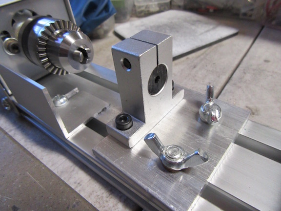
By the way, the hasp replaces the "tool post" and this is the tool post that came with the machine (minus the holes I drilled):
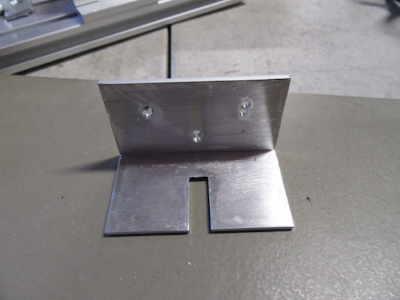
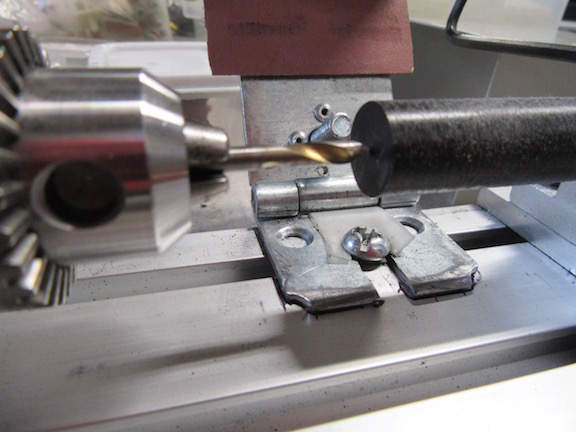
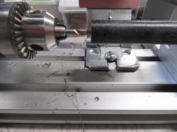
I took the hasp and drilled 2 - 1/4" holes, in line and close to each other because I needed to create a slot in the hasp base.
I used the rat tail file to create a throughway, then used the flat file to finish the slot.
I decided there was too much play between the hinge pin, (the excessive play caused the hasp to jump around too much) so I cut a strip of nylon slider tape, to take up the gap, thus eliminating most of the play. You can see the nylon strip between the screw holes.

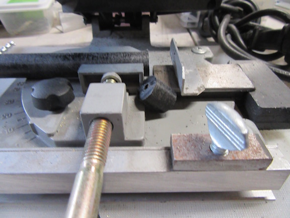
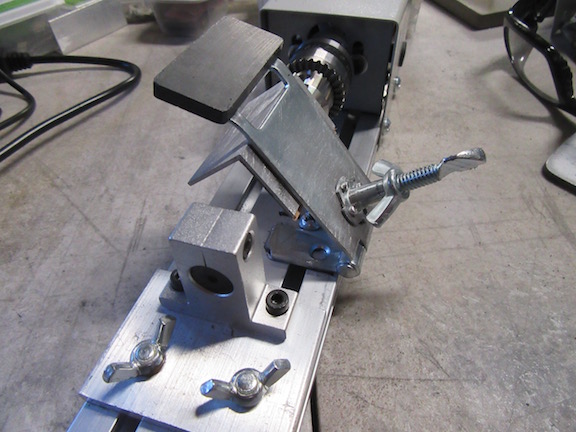
Here is the hasp mounted with the angle aluminum, thumb screw and tee nut installed. (I used the VHB RP tape to mount the angle aluminum -- the Tee nut is riveted on)
I employed the thumb screw as the "stop", so you can set whatever diameter you wish to cut the tire down without having to continuously check the diameter of the tires.
I put a bend at the top of the hasp, for placement of a weight to keep the hasp from bouncing around when cutting the tires.
I employed a magnet that I had lying around, which was the exact weight needed - yet not too heavy to place a strain on the motor.
The wing nut locks the thumb screw in place, and is intentionally upside down for hand clearance, when turning the adjusting thumb screw and locking it in position.
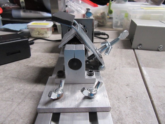

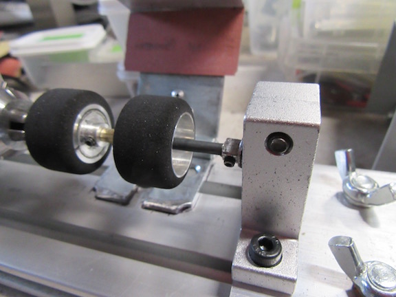
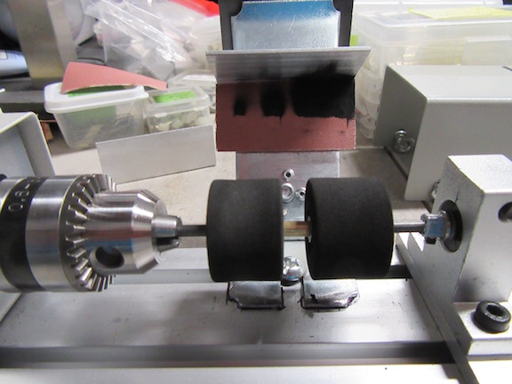
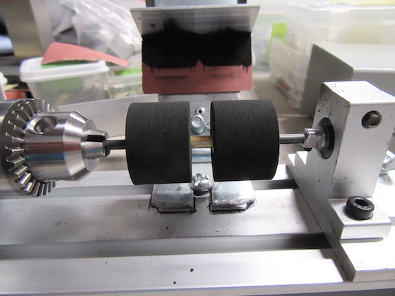
I needed to groom some old tires to fit my current project, I put them into place for inspection/alignment.

These tires were squished in a box full of other tires, and as I pulled them out, they were a little deformed.
You can see the rolling surface of the tires are obviously not flat!

Pulled down the hood for the initial test cut -- I'm using adhesive back #240 grit auto body sandpaper to remove material.
After approximately 30 seconds, I pulled up the hood and you can see how the rubber residue indicates the cutting pattern.
After a couple more 30 second cuts, this is the cut pattern.

Getting better!
After a few more 30 second cut times, it is done!
I choose to use 30 second cut times, because material removal is fast.
After each cut time, I remove (brush off) the residual material to avoid clogging the sandpaper.
I also noted that the acetal/delrin bushing does not get warm when the axle rod is spinning for a length of time - that's a good thing to me!
The axle rod spins real smooth inside the bushing.