Jump to content


Photo

By accident! anglewinder build


  • Please log in to reply
14 replies to this topic

#1 Alchemist

Alchemist

    Posting Leader

  • Full Member
  • PipPipPipPipPipPipPip
  • 2,676 posts
  • Joined: 11-November 09
  • Gender:Male
  • Location:Far, far away

Posted 10 October 2019 - 12:38 AM

Greetings,


A few weeks ago, my wife and I were running our slot cars at Fast Track Hobbies, in Rocklin, CA.


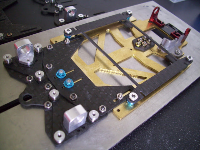
She was running my first gen composite chassis, which I salvaged the angle motor bracket from my damaged stamped steel chassis, and bonded them onto the composite.


For some reason she got distracted and slammed full throttle into the guardrail at the end of the straightaway!


The noise was pretty loud that turned a few heads.


Well, I was pleased that my composite chassis survived without any damage, BUT, the stamped steel motor bracket took a big hit, got bent as well as bending the 1/8 axle?!


I repaired the motor bracket and it runs/handles just as well if not better than before.


Here are pix of the damage.


Big chunk of "quarter panel" broke off!

AW Crash_1.jpg


Slightly Bent - LOL

AW Crash_2.jpg

AW Crash_4.jpg

AW Crash_7.jpg


So, due to this "fortuitous accident" I felt inspired to fabricate my own version of an angle motor bracket.  I do enjoy the challenge - LOL!


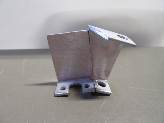
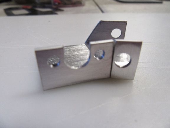
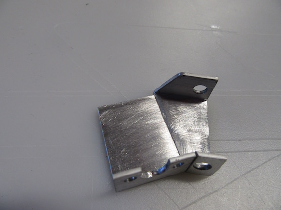
Started out with aluminum C-Channel

AWB_1.jpg


I 'imagineered" the motor and axle brackets as a gestalt (2 pieces combined to produce a whole) - then hand cut, drilled and filed the pieces into this.

AWB_2.jpg

AWB_3.jpg


If you look closely at the following picture, you'll notice the hole for the axle bearing height is slightly below the motor shaft plane.  The purpose is to be able to run smaller diameter wheel/tire.  

I also slotted the motor bearing hole, as well as drilling slightly larger motor mount screw holes, so I could have east/west sliding adjustment to accommodate pinion/spur gear selection.  

AWB_4.jpg

AWB_5.jpg

AWB_6.jpg


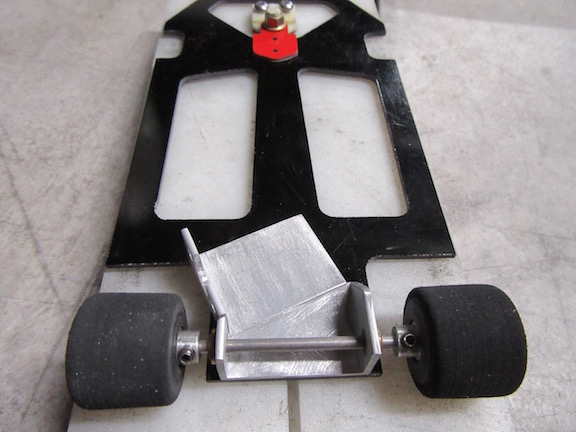
Motor and axle brackets positioned and mounted onto the chassis

AWB_7.jpg

AWB_8.jpg


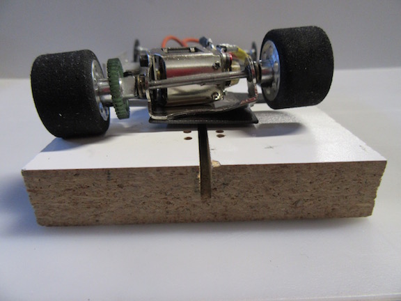
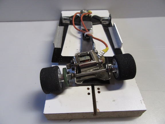
Motor, gears, axle and tires installed

AWB_9.jpg

AWB_10.jpg

AWB_11.jpg

AWB_12.jpg


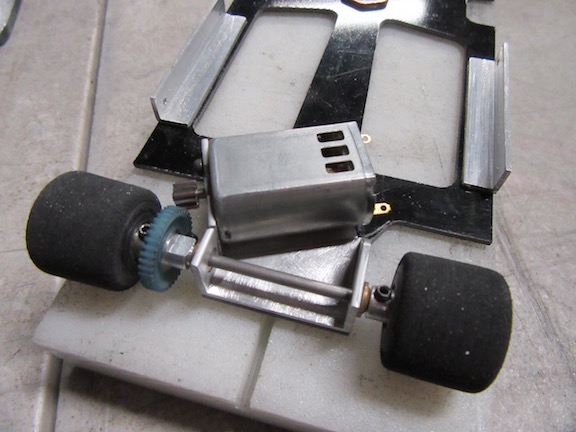
It has a very smooth gear mesh - using 64 Pitch, 12 tooth pinion/39 tooth spur.


My Version 1- AW prototype handles very well, but the chassis was needing to run .880 or larger diameter tires - this version (2) allows me to run smaller .780 OD tires.


My next project is build an AW bracket to accommodate my CCW running motors.


Thanks for looking!


Ernie


  • The Number of, NSwanberg, Peter Horvath and 5 others like this
Ernie Layacan


#2 NSwanberg

NSwanberg

    Posting Leader

  • Full Member
  • PipPipPipPipPipPipPip
  • 2,004 posts
  • Joined: 01-April 09
  • Gender:Male
  • Location:Canton, MI

Posted 10 October 2019 - 04:27 AM

How are the imagineered pieces attached to the chassis?


Remember the Steube bar! (ask Raisin)
SUPPORT YOUR LOCAL RACEWAY!!
"The denial of denial is the first sign of denial." Hank, from Corner Gas

"Death before disco!" Wanda from Corner Gas
Nelson Swanberg 5618

Peace be with all of us and good racing for the rest of us.
Have controller. Will travel. Slot Car Heaven


#3 The Sawdust Man

The Sawdust Man

    Mid-Pack Racer

  • Full Member
  • PipPipPip
  • 135 posts
  • Joined: 24-October 16
  • Gender:Male
  • Location:Canton, MI

Posted 10 October 2019 - 04:38 AM

Now that is just flat out cool!


Robert Manzitti

#4 Bill from NH

Bill from NH

    Age scrubs away speed!

  • Full Member
  • PipPipPipPipPipPipPipPip
  • 14,317 posts
  • Joined: 02-August 07
  • Gender:Male
  • Location:New Boston, NH

Posted 10 October 2019 - 05:24 AM

Ernie, the new anglewinder looks great! Had you thought of making the motor mount & axle uprights in one piece, then bend one wall of the channel to set the motor angle? Similar to the original Slotworks flexi. Your bent steel motor mount looks like it came from a JK Scorpion. Those could bend easily, the SS ones were stronger. Since you say you had to use .880 tires with it, it must have been from a 4.5" flexi.


You could also consider 3D printing for future motor mounts, be they inline, anglewinder, or full sidewinder.


Bill Fernald
 
I intend to live forever!  So far, so good.  :laugh2:  :laugh2: 

#5 Steve Deiters

Steve Deiters

    Posting Leader

  • Full Member
  • PipPipPipPipPipPipPip
  • 2,288 posts
  • Joined: 28-May 07
  • Gender:Male
  • Location:Cincinnati, OH

Posted 10 October 2019 - 09:45 AM

Any info on the motor that was used in the rebuild?


#6 Alchemist

Alchemist

    Posting Leader

  • Full Member
  • PipPipPipPipPipPipPip
  • 2,676 posts
  • Joined: 11-November 09
  • Gender:Male
  • Location:Far, far away

Posted 10 October 2019 - 10:52 AM

Hi Nelson,


The pieces are mounted with 3M RP series bonding tape which I explain in detail in my "Not your typical scratchbuilt chassis" thread:  http://slotblog.net/...is-a-retro-mod/


Hi Bill,


Had you thought of making the motor mount & axle uprights in one piece, then bend one wall of the channel to set the motor angle? 


Yes, I did attempt that a few times, but did not find my efforts satisfactory.


You could also consider 3D printing for future motor mounts, be they inline, anglewinder, or full sidewinder.


I have had a motor bracket scanned and 3D printed, which were nice enough.


For me, the drawback of having the part scanned and 3D printed,  was the substantial cost of having it made that way.


I just enjoy working with aluminum and have plenty of scrap aluminum to work with.


I attempted quite a few times, to make a "1 piece" bracket, but to no avail, considering my simple tools and skill.


Thank you Bill - always appreciate your suggestions!


Ernie


  • NSwanberg likes this
Ernie Layacan

#7 Alchemist

Alchemist

    Posting Leader

  • Full Member
  • PipPipPipPipPipPipPip
  • 2,676 posts
  • Joined: 11-November 09
  • Gender:Male
  • Location:Far, far away

Posted 10 October 2019 - 11:47 AM

Hi Steve,


Any info on the motor that was used in the rebuild?


This is an FK-132 size motor, which is slightly longer than the FK-130 size motor.


The specs of this motor, to me, is impressive for the price.   


The motor is rated 44,000 rpm @ 6 Volts.


I have at least 10 hours+ on the few cars that employ this motor and have not had one fail or lose performance - at least not yet!  LOL


I purchased these motors many years ago @ .99 cents/piece - the price has now doubled at about  $2.15/piece - LOL!


My wife has a couple of anglewinder cars, one powered by a Proslot 4002FK motor, the other runs a JK M3 Hawk (the 58K rpm) motor.


For comparison (in my experience) this FK132 motor, geared 9/28 48 pitch, running in my inline composite chassis, is just as fast on the "Reverse Kingleman" track straightaway.


For playing around with my slot cars, I'm quite pleased with the performance of this motor.


Here's a motor comparison photo.

Motor Comparison.jpg


For those interested, here are the motor weight specs on these particular motors:


FK-130:  21.7 grams

FK-132:  28.6 grams

FK-180:  33.0 grams


Thanks for asking Steve!


Ernie


Ernie Layacan

#8 Bill from NH

Bill from NH

    Age scrubs away speed!

  • Full Member
  • PipPipPipPipPipPipPipPip
  • 14,317 posts
  • Joined: 02-August 07
  • Gender:Male
  • Location:New Boston, NH

Posted 10 October 2019 - 11:50 AM

If I had access to a lot of aluminum material, I'd continue to use it too. :) I only mentioned 3D printing because it's "leading-edge technology" & is often used for 1/32 chassis & chassis parts. Which body is that in your post #1? I don't recognize its side silhouette. Thanks.


I knew there was an FK-130 & FK-180, but didn't know there was a FK-132. If Mabuchi kept the same numbering sequence, it's .02" longer than the FK-130. The FK-132s now on ebay are 36K RPM rather than 44K & if you buy 3 or more, they're $2.02 each.


Bill Fernald
 
I intend to live forever!  So far, so good.  :laugh2:  :laugh2: 

#9 Alchemist

Alchemist

    Posting Leader

  • Full Member
  • PipPipPipPipPipPipPip
  • 2,676 posts
  • Joined: 11-November 09
  • Gender:Male
  • Location:Far, far away

Posted 10 October 2019 - 01:11 PM

Hi Bill,


I knew there was an FK-130 & FK-180, but didn't know there was a FK-132. If Mabuchi kept the same numbering sequence, it's .02" longer than the FK-130.


There is also an FK-131 size motor that weighs in at 23.9 grams.


I do not know if these motors I have, are made my Mabuchi, but these are the motor lengths, since all basically have the same width and height.


FK-130:  0.993"

FK-131:  1.089"

FK-132:  1.110"

FK-180:  1.260"


Here are all the FK 130 thru FK180 series motors - side by side.

Motor Comparison2.jpg


Thank you.


Ernie


Ernie Layacan

#10 Alchemist

Alchemist

    Posting Leader

  • Full Member
  • PipPipPipPipPipPipPip
  • 2,676 posts
  • Joined: 11-November 09
  • Gender:Male
  • Location:Far, far away

Posted 10 October 2019 - 01:56 PM

Bill,


Which body is that in your post #1? I don't recognize its side silhouette.


That is an old .010" - ToyTech Racing (Shadow GT-1) body that I believe was replicated from the Audi RSC body (because it looks so similar to me), of course with subtle mods.


Thank you for asking.


Ernie


Ernie Layacan

#11 Alchemist

Alchemist

    Posting Leader

  • Full Member
  • PipPipPipPipPipPipPip
  • 2,676 posts
  • Joined: 11-November 09
  • Gender:Male
  • Location:Far, far away

Posted 10 October 2019 - 03:25 PM

Bill,


 Had you thought of making the motor mount & axle uprights in one piece, then bend one wall of the channel to set the motor angle? Similar to the original Slotworks flexi.


As I mentioned, I was unable to fabricate a one piece motor/axle bracket.


The 2-piece motor bracket/axle bracket idea was inspired by the phenomenally crafted Euro-chassis cars created and built by Nick de Wachter and Fola Osu.


Fola Chassis - Slotfabrik

post-4-0-62998100-1410089054.jpg


Nick's chassis

101_2349.JPG


Just wanted to give credit to the two builders for the inspiration.


Thank you.


Ernie


  • Geary Carrier likes this
Ernie Layacan

#12 Alchemist

Alchemist

    Posting Leader

  • Full Member
  • PipPipPipPipPipPipPip
  • 2,676 posts
  • Joined: 11-November 09
  • Gender:Male
  • Location:Far, far away

Posted 17 October 2019 - 12:28 PM

Hi Bill!


Had you thought of making the motor mount & axle uprights in one piece,


I'd been cogitating on your suggestion, which I mentioned  I had been stymied in my attempt.


Well, I made it one piece by using epoxy adhesive.


It may have started out as two pieces but it IS one piece now!  LOL


Thank you Bill, for the suggestion/motivation/inspiration, to push me to create a one piece bracket.


Aligning the two pieces was such a challenge when bonding onto my composite chassis.


Now, being one piece definitely makes it easier to bond in place.


Here are a few pictures.

AW Bracket_1piece_1.jpg

AW Bracket_1piece_2.jpg

AW Bracket_1piece_3.jpg

AW Bracket_1piece_4.jpg


Thank you for looking!


Ernie


  • Geary Carrier, Jaeger Team and Gor like this
Ernie Layacan

#13 Gor

Gor

    Rookie Keyboard Racer

  • Full Member
  • Pip
  • 14 posts
  • Joined: 09-September 19
  • Gender:Not Telling
  • Location:San Francisco

Posted 18 October 2019 - 10:48 AM

Ernie, the parts look great. Thanks for sharing these photos of your work with aluminum. You are obviously very skilled in the use of a variety of materials, composites, and adhesives.


I hope you won't mind me dropping in on another one of your threads with some more photos.


I've been experimenting with aluminum brazing. These two small pieces of aluminum sheet were brazed together with a butt joint, similar to the joint between your bracket parts. The joint has excellent strength and the joint itself has virtually disappeared. During destructive testing, the two pieces bent and deformed before the joint failed.  


If you have not already used this method, this might be another technique that you could use to join your aluminum parts.


Oct 18_1.jpg


oct 18_3.jpg


Cheers,

Matt 


  • MSwiss, Alchemist and Geary Carrier like this

Matt Ryder


#14 Alchemist

Alchemist

    Posting Leader

  • Full Member
  • PipPipPipPipPipPipPip
  • 2,676 posts
  • Joined: 11-November 09
  • Gender:Male
  • Location:Far, far away

Posted 18 October 2019 - 12:31 PM

Hi Matt,


Thanks for dropping by and sharing.


You may not have seen my "Not your typical scratchbuild" thread where I explained that I prefer not to do any type of soldering/welding/brazing.


Which is why I have chosen to employ alternative "bonding" methods for my scratchbuids.


I have used aluminum brazing rods with a pencil torch, which works very well.


One caveat when brazing aluminum, is to remove the anodized coating on the area being brazed.


That is if  "architectural aluminum" is purchased from the home improvement centers.


Your willingness to share is very much appreciated Matt!


I've been experimenting with aluminum brazing.


By the way, since you experimenting, perhaps this might interest you.


They make a single component, low temperature, heat cured epoxy adhesive.


What makes this unique is that you can join dissimilar substrates.


Although optimal properties with epoxies, are obtained with the higher temperature cure, the lower curing temperature still provides reasonably good physical strength values.


For our slot car use, I'm sure it would work well!


Thanks again Matt!


Ernie


p.s. Did you happen to grow up in San Francisco in the 60's when the Ocean Beach Modelcar Raceway was around?


Ernie Layacan

#15 Gor

Gor

    Rookie Keyboard Racer

  • Full Member
  • Pip
  • 14 posts
  • Joined: 09-September 19
  • Gender:Not Telling
  • Location:San Francisco

Posted 18 October 2019 - 09:51 PM

Hi Ernie, thanks for your gracious reply. Yes, I had missed your "Not your typical scratch build" thread. After reading it through, it confirms my impression that you are very skilled and experienced with adhesive bonding. Your work is very interesting, I'll look forward to more.


Unfortunately I never got to see the Playland Raceway. Back then I was in Ohio playing with HO.


Matt Ryder


Electric Dreams Online Shop