Jump to content


Photo

Homebuilt four-lane AFX lap counter


  • Please log in to reply
5 replies to this topic

#1 Paul Lindewall

Paul Lindewall

    Mid-Pack Racer

  • Full Member
  • PipPipPip
  • 140 posts
  • Joined: 27-September 18
  • Gender:Male
  • Location:SC

Posted 29 May 2020 - 01:33 PM

I built this as a project during my Covid-19 quarantine time. 


  • Cheater, Tim Neja, NSwanberg and 3 others like this


#2 Paul Lindewall

Paul Lindewall

    Mid-Pack Racer

  • Full Member
  • PipPipPip
  • 140 posts
  • Joined: 27-September 18
  • Gender:Male
  • Location:SC

Posted 29 May 2020 - 04:09 PM

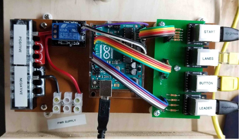
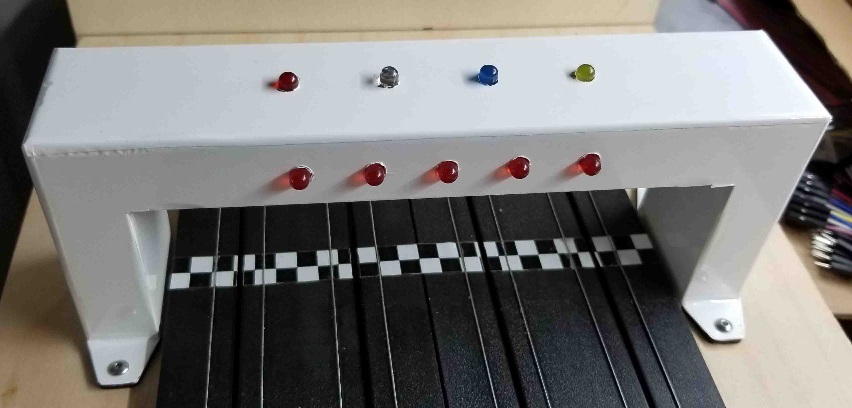
Once I knew everything was working correctly, I cleaned things up by mounting the Arduino, relay, Ethernet jack/resistor PCB, and some terminal blocks for easy power connections on a module. And, I finished off the gantry by covering it in a gloss white Ultracote (RC airplane covering)


Module.jpg Gantry.jpg


  • Tim Neja, Phil Smith, NSwanberg and 1 other like this

#3 SpeedyNH

SpeedyNH

    Old Engineer

  • Full Member
  • PipPipPipPipPip
  • 767 posts
  • Joined: 18-July 15
  • Gender:Male
  • Location:Cow Hampshire

Posted 30 May 2020 - 04:07 PM

that's cool. maybe adaptable to a light bridge instead of reed relays? 


Steve Lang


#4 Paul Lindewall

Paul Lindewall

    Mid-Pack Racer

  • Full Member
  • PipPipPip
  • 140 posts
  • Joined: 27-September 18
  • Gender:Male
  • Location:SC

Posted 31 May 2020 - 07:34 AM

Actually, the bridge is designed (by me) to accept 5mm LEDs over the lanes, with 3mm sensors in the track. That's what I have on my Viper track. My first (AFX) track used TrackMate IR sensors, and I wasn't particularly happy with the way they were supposed to be 'mounted' in the track - a blob of hot glue, allow to harden overnight, drill, and slide the sensor in and hope it stays in place. I'm going to be experimenting with some 3mm flat top light sensitive diodes that will mount flush to the track surface and can be glued in, with the 5mm standard LEDs in the gantry. Yes, there will be visible light, but just under the bridge, and I think the ease of mounting the track sensors will make up for it. At least that's my future plan. 
 
I really like the Arduino systems. They are highly customizable. My track uses the gantry with start lights, lead lights, and IR emitters, with IR sensors in the track. Individual lane power relays with individual track call buttons means that any driver can trigger a stop, but on restart, his lane doesn't get powered up until he suffers a time penalty. There is a Master call button for track issues other than de-slots that stops and starts all cars, but doesn't penalize any lane. You can also set up a jump start penalty. Additional relays control red and green lights on each driver station, and around the track. It uses an Arduino Mega 2560 board because it has extra sockets for more pins.

#5 Paul Lindewall

Paul Lindewall

    Mid-Pack Racer

  • Full Member
  • PipPipPip
  • 140 posts
  • Joined: 27-September 18
  • Gender:Male
  • Location:SC

Posted 31 May 2020 - 05:33 PM

Updated video.


  • cuda man likes this

#6 Michael Jr.

Michael Jr.

    Checkered Flag in Hand

  • Subscriber
  • PipPipPipPipPipPip
  • 1,157 posts
  • Joined: 24-April 14
  • Gender:Male
  • Location:Spartanburg, SC

Posted 01 June 2020 - 08:15 AM

Paul that's a beautiful piece of work. The quality can be seen in just how neat you made everything. My wiring looks like a tangled web or something from space.  Really really excellent work.


Michael Cannon

Upstate Speedway

100 McMillian St.

Spartanburg, SC 29303


Electric Dreams Online Shop