Jump to content


Photo

CMF3 1237-series design concept


  • Please log in to reply
5 replies to this topic

#1 Rick Moore

Rick Moore

    CMF3

  • Full Member
  • PipPipPipPipPip
  • 500 posts
  • Joined: 22-November 09
  • Gender:Male
  • Location:Tampa

Posted 10 June 2020 - 09:08 AM

1237-Series Design Concept, Preface


This is a post some of those out there looking at this weird stuff I’ve been building since the beginning of 2016 have probably been to some level curious about. Since the 1237-Series has surprisingly, particularly to me, turned out to be much more successful than I originally imagined, thinking at the onset they’d be at best just a sidebar in my chassis designs, and now, over 50 design/builds later (not to mention the duplicate builds, and designs that didn’t get built), it is long overdue that I at least make some attempt to outline the premise and hypotheses behind all these chassis.


Is this a better way to design or build chassis that win lots of big races? Nope. Definitely not, for lots of reasons; I have mine, and no doubt others have theirs. It is merely a different way to design and build a chassis, and that is the challenge I wanted, and is all I can offer.


“Design Concept”, applying certain restrictions concerning the usage of profanity, scatological references, and countless disgustingly vile analogies, might be better described as, “Why Not?”


Questions are welcomed, though answers may not be definitive, since the 1237-Series is still an active study, and carry the often used caveat, “Subject to change”.


So, if you’re really bored, grab a frosty beverage, put on some background tunes, cop a comfy seat, and read on through this rambling narrative of design concept and WAG’s for the 1237-Series chassis. Waders are optional. I’ll try to keep it short and simple… Haha… Oh, that sounded utterly ridiculous…I’ll just apologize up front here for the unnecessary length and any additional confusion. Consider yourselves warned! Or, maybe that should be, abandon all faith ye who enter here!


Enjoy!


Rick / CMF3


#2 Rick Moore

Rick Moore

    CMF3

  • Full Member
  • PipPipPipPipPip
  • 500 posts
  • Joined: 22-November 09
  • Gender:Male
  • Location:Tampa

Posted 10 June 2020 - 09:13 AM

1237-Series Design Concept, Part 1; Developing the 1237:


First things first. The objective was to design a chassis with an all-wire frame (no structural brass plate or sheet) using 0.032” wire…


All-Wire Framing; pre-1237 History:


My original all-wire framed chassis (early 12XX numbered) were largely an exercise to see if it could be done. All these early frames were built using 0.047” wire. By the “12-teens”, I’d figured it could be done, and with some definite possibilities, but also some inherent problems. With the 1218 I began to get a handle on those early lessons, and finally built a viable frame.


Eventually, the 1219 became the first design/chassis where I could start to incorporate these observations in a series of chassis designs and builds. In the 1219-Series, the 1225 would become the first all-wire chassis design to be built in a variety of dimensions; it also became the first design to be built not only in 0.047” wire as before, but also built using 0.039” wire, and eventually in 0.032” wire. That last one, the 0.032” wire framed 1225-Ca3, was an eye opener; rocket fast and absolutely unpredictable; what it taught me was that for 0.032” wire the 1225 design was all wrong. By the 1229’s I had decided to create “component based” designs to address some of the functional shortcomings. As it would turn out the 1229’s were better as 0.039” frames than 0.047”, and were almost as good when built using 0.032” wire, but still had some loading issues. The 1233-Cc3 was the first successful 0.032” wire framed chassis, but was still basically a 1219-Series design, and had to incorporate a lot of complex “anti-harmonics” for it to work. The 1234 and 1235 never got built. It was time to try something else. This is where the 1237 Series came in.


The 1220-C:


1220-C-ae.jpg


The 1225-Ca:


1225-Ca01e.jpg


The 1229-Cb2


1229-Cb2-bo5ae.jpg


All-Wire Framing; 1237-Series:


It had become apparent that in order to build all-wire framed chassis using 0.032” wire that any structural rail (in this discourse “rail” meaning a lone or set of wires connecting two chassis points, not the wire itself; example, a “rail” of 4x 0.032 “wire”) should be as short as possible. By limiting the length, and triangulating/angling the rails, two problems could be solved; one, the component rails could have fewer/shorter wires with equal or greater strength, and; two, the multiple angles/directions of the rails should significantly decrease harmonic vibrations and lateral “spring” loading of the chassis frame.


All-Wire Component Chassis Design:


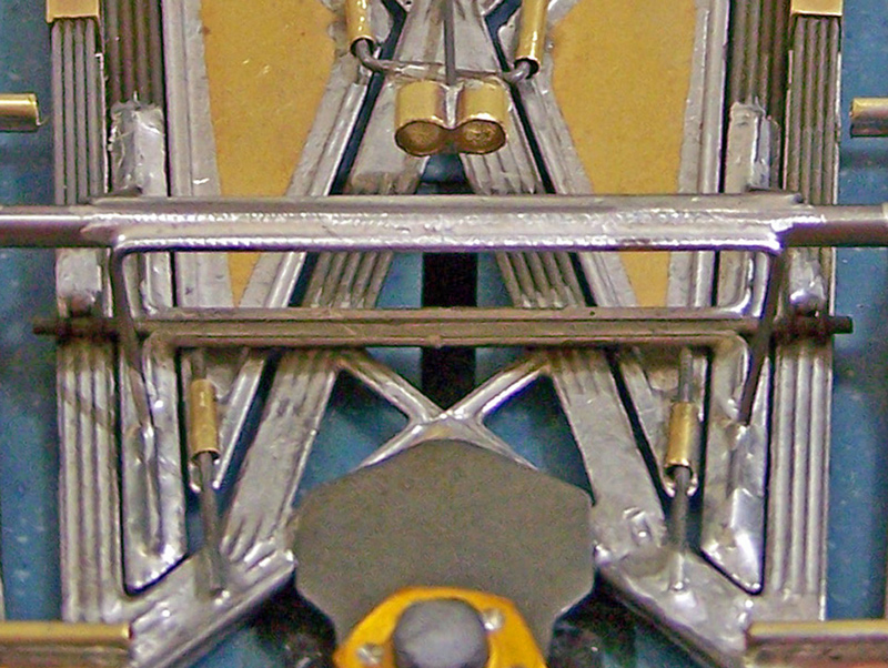
The concept going in was to have “separate” design elements and assemblies in the all-wire framing that would be interconnected with the framing wires. The concept is pretty basic; it is no different than a kit having preformed brass front/guide plate, side pans, motor bracket, and connecting them together in some fashion. The challenge was to incorporate this “sectional design” concept into an all-wire frame that in essence has no separate components, but still making these components wire-only assemblies that would be adaptable in themselves while being able to be integrated as a whole.


Rear Motor/Drive Assembly:


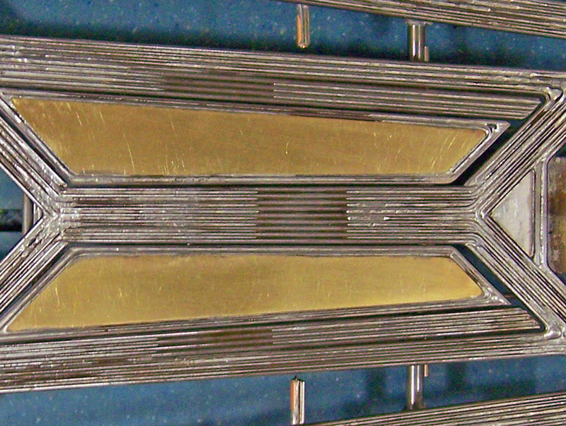
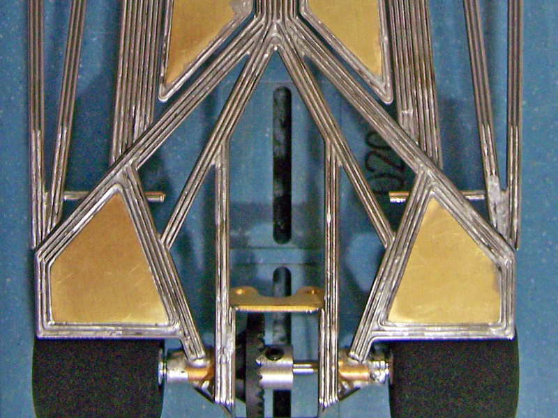
This is the triangulated portion of the rear of the frame that contains the motor box, rear axle tube and uprights, and lateral rear “wings” forward of the rear wheel wells. The motor/drive as a separate design assembly was originally a concept on the 1229, and worked well. As a “triangulated” unit it removed a lot of the structural problems when building with smaller wire (0.039” and 0.032”). The 1237 is a simplified design of those previous chassis, making it more triangulated, and with a more simplified wire layout, allowing for more design possibilities of the rear motor/drive assembly itself, and for the main rails.


1237-Cb3-01ad01e.jpg


Rear Motor/Drive Assembly Static Pans:


The lateral rear “wings” forward of the rear wheel wells on the first 1229’s were wire framed “holes” without the brass sheet pans filling them. One day after testing I noticed a pile of rubber and “track crud” loaded up on the wires in front of the rear tires, and I got to thinking about all the “rubber-crud bits” that had gone through the holes… How many times can the same crud bit go around the tire and get thrown back on the track in front of the tire again? Does it matter? As an experiment I took one of the 1229’s and filled the open area forward of the rear tires with a small cut-out of 0.010” brass sheet; the improvement was noticeable, and surprisingly quantifiable. The same was true when I did this to other 1229’s. And always with a fair amount of “track crud” on them. Originally these pans were about 7/16” (≈0.43”) forward of the rear axle center, but, since they are fixed, or static, pans, I did an additional experiment building another 1229 with the static pan framing only 0.30” forward of the rear axle center (they sit under the forward circumference of the rear tire, leaving only about enough space between the rear tire and the framing for a 0.047” wire to pass); this worked even better. They do need to be cleaned regularly. These rear static pans were incorporated into the 1237-Series.


Front Spanning Assembly / Front Wings:


Early attempts at all-wire framed chassis with a straight lateral spanner perpendicular to the centerline (with the guide tongue mounted atop) were structurally deficient, bending too often with front corner impacts (the most common). Alternatively/subsequently a V-shaped spanner was made, creating a guide well, and extending at a 45-degree angle to the “boxed” front wings. This structural layout has proven to be much stronger and effective in maintaining the guide and chassis front integrity.


Front Wings / Side Pans:


The 1237-Series simplified and standardized these assemblies. These two elements have a common medial line, making the side pans an extension of the front wings, separated by the front wheel wells with angled sides for better structural strength. The front wings are boxed between the lateral ends of the front spanner and the front wheel wells using a minimum of wires to attain the strength required, but keeping the mass low. The side “pans” are even more minimal, to allow for sufficient flex and body movement, while minimizing the chassis mass moving vertically.


1237-Cb3-01ad02e.jpg


Main Rails:


Design/build experimentation of main rails in early all-wire frames had brought one obvious conclusion: main rails that were straight and parallel to the centerline were structurally weaker than main rails that angled from the rear to the front, whether converging, diverging, or a combination. Long straight/parallel rails had to incorporate more wires to get the same strength, and were still more prone to being knocked “out of whack”, skewing the frame (askew... gesundheit…).


The 1219-Series had used a pair of main rails, direct or indirect, that converged rear-to-front (the same rear-to-front orientation will be used for main rail descriptions throughout) from lateral of the motor box to lateral of the guide mount on the front spanner.


The original “doodle” of what would become the 1237 ran a single center-line main rail from the forward apex of the triangulated rear motor/drive assembly to the apex of the triangle at the guide mount on the front spanner. It was significantly shorter, approximately 30%, than the previous 1219-series main rails. As simple as it was, it could solve a lot of the loading problems inherent in the longer converging pair of main rails. The question was stability…


Buttress Rails:


On the original 1237 “doodle” I drew in two more converging main rails as those on the 1219-Series, which made it a “tri-rail” chassis. They added the planar stability to the center main rail, but made the chassis basically another 1219-Series with a center main rail added, which was not what I was trying to design. On a whim I erased the connection points of these two rails where they met the rear motor/drive assembly, and made the notation, “articulate” with a question mark. This in effect kept the frame a single center main rail with the added stability it needed. Maybe. For lack of a better term these rails, “secondary articulated main rails”, would be referred to as “buttress rails”. Eventually the articulation would be devised as simply two small pieces of brass tubing, one soldered to the front of the rear motor/drive assembly, and the other soldered to the disconnected rear end of the buttress rail, with a piece of wire soldered inside on the buttress rail’s piece of tubing.


1237-Cb3-01ad03e.jpg


The Base 1237:


From my experience with previous designs it was apparent the 1237 would work as a frame constructed using 0.039” wire, and as a matter of discretion in the build progression the first 1237 would be 0.039” wire framed. The initial 1237-Cc2 frame spent about two weeks missing most of its superstructure as it was subjected to a lot of bending, twisting, prodding, and generally being stared at. After its completion the second 1237 chassis, the 0.032” wire framed 1237-Cc3, was built, and would be found to be not only structurally sound, but with better performance than the 0.039” wire framed 1237-Cc2, and better than all the previous 1219-Series chassis, 0.032” wired framed or otherwise.


Subsequent designs, builds, and testing would indicate the numerous components used to negate loading and harmonic problems with 0.032” wire framed 1219-Series chassis were not needed on the 1237-Series 0.032” wire framed chassis.


The basic 1237 design was complete, and the 0.032” wire framed 1237-Cc3 had confirmed proof of concept.


1237-Series Design and Build Progression:


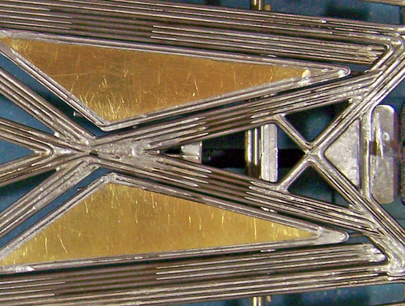
The 1237 design has three basic and distinct framing components: 1) the rear motor/drive assembly; 2) the main / buttress rail assemblies, and: 3) the front spanner / front wings / side pans assembly. Variations could be made to any one or part of the separate components allowing for an easy progression of design changes.


1237-Cb3-01ad04e.jpg


And that is when the fun began!


Rick / CMF3


  • bluecars, Eddie Fleming and Greg Erskine like this

#3 Eddie Fleming

Eddie Fleming

    Posting Leader

  • Subscriber
  • PipPipPipPipPipPipPip
  • 2,909 posts
  • Joined: 27-April 14
  • Gender:Male
  • Location:Fayetteville, GA USA

Posted 10 June 2020 - 10:37 AM

To me the trick is in tying the three components together. Some if not all the wires from each section must be integrated into the connecting section to form a strong joint and that is the magic part of this construction.


Drive on! :)


Eddie Fleming

#4 Rick Moore

Rick Moore

    CMF3

  • Full Member
  • PipPipPipPipPip
  • 500 posts
  • Joined: 22-November 09
  • Gender:Male
  • Location:Tampa

Posted 20 May 2021 - 10:35 AM

1237-Series Design Concept, Part 2; Front Axle Rails:


Front axle rails (FAR’s) are quite simply separate rails upon which to mount the front axle uprights and front axle, as opposed to having the front axle assembly as a superstructural extension of the main rails. Certainly not a new idea, the premise is to minimize any forces working on the front wheels from the rest of the chassis.


Prelude; Front Axle Mounting:


For solid, straight front axles I have been using front and rear superstructural spanning front axle uprights since… well… the first ones I built were in late ‘68 - early ‘69, not long before the last of the “local” slot car raceways closed in MD, ending my “young” slot car geek phase until my “old” slot car geek phase began in 1995 FL. The front axle spanning uprights had a few advantages I liked: as chassis superstructure there was no need to incorporate a bend in any of the main rail wires as front axle uprights (or, to a lesser degree, add uprights as separate wires between spaced main rail wires); rather than the axle or axle tube being soldered in only at the axle uprights’ points of contact, the axle was soldered in along the entire width of the spanner, eliminating any need to tie-wire the axle to the uprights. Additionally, the front axle, and even the spanning uprights, were relatively easy to remove / reposition / replace.


Not surprisingly, some thirty-five-plus years later when I went back to scratchbuilding chassis, for those chassis that had (or had to have) straight front axles I went right back to using front and rear superstructural spanning front axle uprights for all those same reasons. Another reason would be how they easily facilitated the incorporation of FAR’s into chassis.


Front axle spanning uprights


FAR001ae.jpg


FAR’s, History:


The three important points of track contact for any slot car chassis are the two rear tires and the guide. For all intents and purposes, the front tires are along for the ride, and in many slot car classes are eliminated. This is not an option in the “retro” scratchbuilt chassis classes. Early “no rules” 12XX all-wire framed chassis had front wheels that were largely for aesthetics, no more touching the track surface than the front corners of the chassis, if at all. This could not be the case for the retro builds, where chassis front clearance and the front wheels contacting the track surface are mandated.


I would quickly find that the relatively larger retro fronts (even trued, as they always were) could send varying degrees of unwanted vibration into an all-wire chassis frame. Whether caused by the track surface, handling stresses, or the front wheels themselves, the cause was of little matter. What mattered was the all-wire frame would just exacerbate this negative effect; as an analogy, think of a Slinky attached to a vibrator.


I knew that incorporating strategically placed brass rod / plate / sheet into a mostly steel wire frame will help to lessen vibration (harmonic) effects; we did it Back-In-The-Day, albeit with 1/16diameter rod/wire. More recently I’d been doing it with the steel/brass “13XX” chassis. In the 1219-Series there were “sister” chassis in the “13XX” steel / brass and the steel-only “12XX” frames, using the same design to see the relative effects and chassis characteristics better. With the “12XX” chassis the goal was to make all steel wire frames so brass was not an option, especially as the diameter of the steel wire being used was smaller; even if there was 0.032” diameter brass wire, the differential between the steel and brass properties under the heat of soldering, particularly expansion / contraction, becomes relatively greater, making the chassis build problematic, often resulting in varying degrees of warpage in the chassis component structure.


The other Back-In-The-Day trick was to build an “iso-fulcrum” chassis, which for an all steel wire frame was a potential solution. (I’ll forego any repetition of the history of iso-fulcrum chassis designs, and the subsequent evolution of indie fronts that are not an option with the retro required front axle). As a matter of design and structure, the iso-fulcrum chassis would have a separate motor/drive-to-guide assembly (“drop arm” effectively) with a hinged attachment to the remaining structure(s) including the front axle supports and side pans. A few of my fellow slot car cronies of the way-back-time (and no doubt elsewhere as well) began to build modified versions of iso-fulcrum chassis, where the side pan structure was an extension of the motor/drive-to-guide assembly, and the only thing on the “iso-fulcrum” component was the front axle/wheel support structure; as a matter of differentiation in our local parlance we called them “front axle rails”. As mentioned in the prelude, the local raceways would close by the following year, and that was that for then for us…


Not surprisingly all those years later I would gravitate back to the front axle rail design concept. The only difference was they would not be hinged components, since I was moving away from the use of any hinges in my early 12XX all-wire chassis designs.


The first FAR equipped CMF3 “retro” chassis was the steel wire / brass sheet 1310-C, sister chassis to the steel wire 1225. Also, the 1310-C was the same chassis design/dimensions as the previous 1309-C, with the exception of FAR’s being added to the 1310. With track tests of the 1310-C the improvement over the 1309-C was noticeably evident, and quantifiable. The all-wire 1225-C with FAR’s was built immediately after. All subsequent 1219-Series chassis would incorporate FAR’s. For the 1219-Series all FAR’s were structural extensions of the rear motor-drive portion of the chassis, and were medial to the main rails (with the exception of the 1226, but that’s another story).


To optimize performance iso-fulcrum and FAR movement needs be restricted and moderated. Directionally, FAR’s should not move laterally, nor should they move below the plane of the chassis. They should move upward, vertically only. Early on with the 1310’s it was found this limited FAR movement needed to be moderated for proper tuning. FAR moderation was accomplished by adding a spring wire to the FAR’s. Initially the 1310-C and 1225-C had a “Y” shaped spring wire attached/soldered to the center of the chassis. It was subsequently found that regulating the tension of this spring wire was critical, but hard to duplicate with just soldering the wire in place.


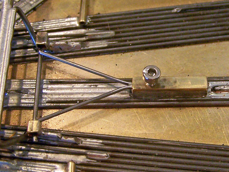
Retrofitted on the 1310-C and 1225-C, using a square brass tube “box” with a screw tapped into it, soldered to the chassis center, and extending the “Y” spring from the inside of the box to resting connections upon the front axle uprights (atop the FAR’s), a variable spring wire (VSW) system was created that could be used to better control the FAR spring wire tension. All subsequent 1219-Series chassis would incorporate FAR’s with a VSW.


1310-C; “Y” VSW
 

FAR002ae.jpg


FAR Design, 1237-Series:


Intentionally, the original 1237 design/build did not have FAR’s; this was done to better assess the basic frame design and build. If the 1237 proved viable, FAR’s would be added with subsequent design/builds.


The 1239 was the first chassis in the 1237-Series to have the FAR’’s. Initial incorporation was to run dual FAR’s flanking medially and laterally adjacent to the buttress rails. The dual FAR’s were soldered to the buttress rails at their rear, adjacent to the buttress articulation. The single “Y” shaped variable spring wire (VSW) set-up of the 1219-Series was abandoned; the 1237-Series would use separate VSW’s per side for each FAR to achieve better left-right control/balance. A VSW box was soldered atop each buttress rail, with the straight VSW extending to a cross member joining the FAR pair at a point below the front axle. On the 1239 and the 1240 the left and right side FAR’s worked independently of each other. A lot of subsequent testing, designing, and mock-ups would lead to some changes to this initial layout of the FAR’s for the 1237-Series.


1239-Cc3; FAR’s (two per side) & indie VSW’s


FAR003ae.jpg


The “2” designated FAR’s:

The design and layout of the FAR’s was modified and simplified with the 1241. Each FAR was now a single 4x 0.032” wire rail located medial to the buttress rail, but still attached to the rear of the buttress rails. On the previous 1237-Series chassis the FAR’s were independent; on the 1241 a torsion bar was added between the FAR’s, located below the front axle; the VSW’s extended to lay atop the torsion bar extension that was atop the buttress rails. In this way the buttress rails were still able to restrict lateral movement of the FAR’s directly (buttress rail on same side FAR) and indirectly (buttress rail on opposite side FAR). This set-up required less overall mass, smoothed out the chassis dynamics further, and greatly improved overall handling and performance.


1241-Cb3; FAR’s (one per side) & indie VSW’s (with Torsion Bar, not visible under front axle)


FAR004ae.jpg


Subsequent FAR design variations, to date:


The “3” designated FAR’s:

The 1250 is a 1241 design with a FAR variation. On the 1250 the FAR’s, still medial to the buttress rails, are not attached to the buttress rails; they are attached to the chassis center via a 3x wire rail; they are also attached indirectly (with 2x 0.024” wires) from the FAR rear to the forward edge on the rear motor/drive assembly. The “3” / 1250-style FAR’s displayed more stable characteristics when running the chassis in high-speed / high-stress turns (and would be incorporated onto “outside” / right-side of LTO / oval racing asymmetric Stock Car chassis.)


1250-Cc3 FAR’s


FAR005ae.jpg


1244-D3o asymmetric FAR’s


FAR006ae.jpg


The “4” designated FAR’s:

The 1251 is another 1241 design with another FAR variation. On the 1251 the FAR’s are “quadrangular rails” that have no direct attachment to the chassis frame, having only 2x 0.024” indirect attachments from the rear of the FAR to the forward edge on the rear motor/drive assembly. This yielded smoother handling, but not enough improvement in overall performance to warrant the increased complexity of build.


1251-Cc3 FAR’s


FAR007ae.jpg


The “5” designated FAR’s:

The 1258.5-Cb3 has a hybrid of the “2” and “4” FAR’s. The FAR is the same 4x 0.032” wire rail as on the 1241, or “2” FAR’s, but it is not attached to the rear of the buttress rail, instead being indirectly attached as on the 1251, or “4” FAR’s, with 2x 0.024” wires to the forward edge on the rear motor/drive assembly. This 1258.5-Cb3 is still under study.


1258.5-Cb3 FAR’s


FAR008ae.jpg


There are other FAR design variations that have not yet been investigated.


FAR Location:


The relative medial to lateral placement of the FAR’s in the 1237-Series chassis frames are inherently dependent on the location of the buttress rails. While experimental mock-up testing used for spring wire location indicated there may be an advantage to having the FAR’s located medially as opposed to laterally, there are limits to this observation when applied in actual chassis construction.


This subject of buttress rail and relative FAR location in the 1237-Series is still under study.


Spring Wire Location Relative to FAR:


Prior to the 1241-Cc3 build some experimentation of design concepts was performed, using older 1219-Series chassis and some mock-ups. This was conducted in conjunction with the possible application of a torsion bar between the FAR’s.


Where the spring wire was located medial relative to the FAR there was an inherent increase in the amount of rotational “twist” between the two FAR’s around the chassis central axis. Moving the spring wires to a position lateral with respect to the FAR’s decreased this effect. The incorporation of a torsion bar (T-Bar) between the two FAR’s was found to decrease this effect even further, where the FAR’s worked more in unison with each other as a greater force was applied to one to mimic cornering (and possibly where one FAR acts as a dampener to the FAR on the other side, though this remains hypothetical).


1254.2-Cc3; T-Bar (view 1)


FAR009ae.jpg


1255.2-Cc3. T-Bar (view 2)


FAR010ae.jpg


FAR Spring Tension:


FAR spring wire tensions, from minimum (no tension other than that of the FAR itself) to maximum (or lock), and their adjustment is an area still under investigation. There have been a lot of observations to date.


The distance from the front of the VSW box to the torsion bar extension / front axle center line for the 1237-Series has been 0.875”. This number was arrived at by locking individual and sets of 0.039”, 0.032”, and 0.024” wires in a vise, then observing and measuring their deflection with force applied at different points. A WAG, basically, but one I could at least see.


Originally 1237-Series chassis with FAR’s, the 1239-Cc3 and 1240-Cc3, used spring wires that were 3x 0.032”. The 1241-Cc3 was built with a set of 3x 0.032” spring wires and a set of (softer) 4x 0.024” spring wires. The 1241-Cc3 using the 0.024” spring wires exhibited better performance. Changing the 1239 and 1240 to 0.024” spring wires improved their performance as well. Another set of 5x 0.020” spring wires were made for the 1241-Cc3 but no improvement versus the 0.024” spring wires could be noted.


On the 1237-Series Stock Car class chassis for LTO oval racing, the 1241-D3o initially, and 1244-D3o subsequently, it was found to have better performance with different spring wires on the inside/left (4x 0.024”, softer) and outside/right sides (3x 0.032”, harder).


All this has led to the fairly safe assumption that optimal spring wire tension(s) being applied to the FAR’s will most likely vary from track to track, and more than likely from one chassis style design/build to another. Since I am working within the confines of the 1237-Series designs / builds at least the latter factor appears thus far to be largely mitigated.


However, there is an observable range of limits to the spring wires having either too much tension (too “hard”) or too little tension (too “soft”), not unlike adjusting suspension springs; respectively, test observations have shown this can cause chassis to “understeer” (or “push”, the car / guide wanting to drive out of a corner), or “oversteer” (or “loose”, the car / rear drive wanting to swing out of a corner). An accurate and repeatable measuring system for VSW tension in the chassis is still in the development phase (in other words, I’m still not happy with methods tried to this point).


Some might think that having the front wheels fully removed from contact with the track where the chassis front wings make contact would be the optimal for chassis handling, but at least within the confines of “retro” rules class racing as it exists this has been found not to be the case as noted in the previous paragraph. Observably on the 1237-Series chassis any time track rubber appears on the chassis front wings there is a corresponding decrease in performance relative to the amount of build-up within the number of laps run (more build-up in fewer laps equals greater decrease in performance). While a little build-up may be acceptable within the course of the number of laps typical of a race heat, particularly on a heavily “rubbered-in” track where it can expected, typically any more than a small build-up on the front wings that can be easily wiped away with a swipe of a finger is not desirable. When “excessive” build-up is observed the FAR spring wire(s) needs to be adjusted for greater tension. While this runs counterintuitive to our collective “slot car knowledge”, it is nonetheless observable and verifiable.


FAR’s, Summation:


While the use of FAR’s on various chassis designs and builds may not be to any advantage, and may even in some cases either be an unwarranted complication or even detrimental, for fully steel wire frames constructed using small diameter wire, to date in my designs and builds from 0.047” to 0.032” wire, the incorporation of FAR’s ranges respectively from advantageous to virtually necessary.


Got all that? Yeah, me neither. What a bunch of malarkey (this sentence to be spoken in your best Bugs Bunny voice, though Daffy Duck will also suffice…).


Your results may vary. Just be sure it’s fun getting to those results.


Rick / CMF3


  • Eddie Fleming and Greg Erskine like this

#5 Rick Moore

Rick Moore

    CMF3

  • Full Member
  • PipPipPipPipPip
  • 500 posts
  • Joined: 22-November 09
  • Gender:Male
  • Location:Tampa

Posted 20 May 2021 - 10:46 AM

1237-Series Design Concept, Part 3; Motor/Drive Assembly and Main Rail Variations;


There have been numerous variations of the Motor/Drive Assembly and Main Rails in the 1237-Series, but the core within the 1237-Series of those variations to date have been the 1241, the 1254, and the 1259.


Part 3a; Motor/Drive Assembly Variations; 1241, 1254, and 1259 Designs:


The 1241 chassis:


The 1241 design, in so far as the Motor/Drive Assembly and Main Rail, is still the base 1237 design. The 1241 is for all intents and purposes a 1237 with the “.2” front axle rails (FAR’s) added. The motor/drive assembly is the same basic triangulated component structure, and the main rail is still the same single center main rail of the same length, dependent on rear axle to guide pivot center (RAx-GPC) and wheelbase (WB) dimensions used for the particular version of the chassis, but still the same for any two 1237 or 1241 chassis of the same dimensions.


1241-Cc3; chassis


MDMR001ae.jpg


1241-Cc3; motor/drive assembly


MDMR002ae.jpg


1241-Cc; main rail (9x wire)


MDMR003ae.jpg


Later revision of the 1241’s, the 1241.2’s, among other revisions, would change the main rail from a 9x 0.032” wire rail to an 8x 0.032” wire rail (the same as on the 1254’s and 1259’s).


1241.2-Cb3; main rail, revised (8x wire)


MDMR004ae.jpg


The 1254 chassis:


The basic concept behind the 1254 design was to shorten the length of the center main rail. The length of the 1254’s main rail was determined geometrically by drawing lines from certain points on opposite sides front-to-rear on the chassis layout and observing their points of intersection with the centerline, which turned out to be in a fairly tight grouping. The averaged point of intersection would be used as the point of convergence (POC) between the forward apex of the rear motor/drive assembly rails and the main rail on the 1254. The result was the 1254.2-Cc3 would have a center main rail that was only 1.375” long, as opposed to the 2.00” long center main rail on the 1241-Cc3, a significant change.


Of course, the 1254’s shorter main rail meant its rear motor/drive assembly would be correspondingly longer. The motor/drive assembly rail layout of the 1241 (ex 1237) would not be structurally adequate to compensate for this increased area. To make up for this, the 1254 would not only have the rails at the forward aspects (for the 1254 and similar designs, lateral aspect rails) of the motor/drive assembly angled to extend further forward, but have new additional structural rails running from the POC to the medial and lateral rear axle tube support rails (for the 1254 and similar designs, medial aspect rails).


1254.2-Cd3; chassis


MDMR005ae.jpg


1254.2-Cd3; motor/drive assembly


MDMR006ae.jpg


1254.2-Cd3; main rail


MDMR007ae.jpg


The 1259 chassis:


After the resulting design of the 1254, I decided to also make another 1254-based design, but this time determining the POC between the motor/drive assembly and the main rail as the mathematical mid-point between the rear axle centerline and the guide pivot center. This gave the 1259.2-Cc3 a center main rail length of 1.6875”, which coincidentally and quite by accident turned out to be exactly half the difference between the 1241-Cc3 (2.00”) and the 1254.2-Cc3 (1.375”) main rail lengths.


For the 1259 the same rail lay-out as the 1254 was used for the motor/drive assembly, but with the angles of the lateral aspect rails and the medial aspect rails altered to compensate for the 1259’s decreased motor/drive assembly area.


1259.2-Cc3; chassis


MDMR008ae.jpg


1259.2-Cc3; motor/drive assembly


MDMR009ae.jpg


1259.2-Cc3; main rail


MDMR010ae.jpg


Continued...


  • Eddie Fleming and Greg Erskine like this

#6 Rick Moore

Rick Moore

    CMF3

  • Full Member
  • PipPipPipPipPip
  • 500 posts
  • Joined: 22-November 09
  • Gender:Male
  • Location:Tampa

Posted 20 May 2021 - 10:53 AM

1237-Series Design Concept, Part 3; Motor/Drive Assembly and Main Rail Variations;


Part 3b; Main Rail Variations, the V-Rail and Iso-Guide Mount; 1256, and 1258 Designs:


Where the 1241, 1254, and 1259 represent the core of the 1237-Series designs, the 1256 and 1258 represent the next step in Main Rail design variation within that core, the diverging “V-Rail”, and the introduction of the “Iso-Guide” mount.


The 1255 and 1256 chassis:


After the completion of the 1254 chassis design two additional designs were also made, the 1255 and the 1256. The difference for these two designs was the main rail configuration. Instead of the 1254’s 8x 0.032” wire single center main rail, the 1255 and 1256 would have two 4x 0.032” wire main rails that would diverge from the motor/drive assembly forward apex, the POC, to points on the front spanner just lateral of the guide tongue mount, giving a “V-rail” configuration to the main rails.


On the 1255 the space between the two diverging main rails would have additional minimal rails extending from the center of the front spanner behind the guide mount attached to and filling the space between the diverging main rails, making it a “solid” structure.


1255.2-Cc3; diverging “V” main rail, with solid guide mount


MDMR011ae.jpg


The 1256 would have similar minimal rails extending from the center of the front spanner behind the guide mount, but were not attached to the diverging main rails, making a separate structure between the diverging main rails that was free to move with any vertical forces applied to the guide. The idea was to allow the guide to move upward at an increased angle to some degree to better adjust for the curvature of banked track curves. A small 0.024” “up-stop” wire was added between the diverging main rails near the POC to inhibit any downward movement of the guide. This chassis configuration I call an “iso-guide”.


1256.2-Cd3; diverging “V” main rail, with iso-guide mount


MDMR012ae.jpg


1256.2-Cc3 iso-guide mount (left) vs 1255.2-Cc3 solid guide mount (right)


MDMR013ae.jpg


The 1257 and 1258 chassis:


Similar variations were done with the 1259 center main rail chassis design. The 1257 had the diverging main rails with the solid guide mount. The 1258 has the diverging main rails with the iso-guide mount.


1257.2-Cc3; diverging “V” main rail, with solid guide mount


MDMR014ae.jpg


1258.2-Cc3; diverging “V” main rail, with iso-guide mount


MDMR015ae.jpg


How the 1259 got “The Wrong Number”:


The fact that the 1259 has a CMF3 chassis identifier that is numerically out of sequence has been haphazardly chronicled within the “1237-Series Design and Build Progression” thread. The thought back then was the single center main rail 1254 would be an “intermediate” build or simply something to “get to” the diverging main rail 1255 and 1256. As such there was no expectation that the single center main rail version, the unnamed phantom “1259”, for the diverging main rail 1257 and 1258 designs would ever be needed or built. In reality it would turn out the 1255 was the actual intermediate build between the 1254 and 1256. By the time I made this realization the 1257 had already been built, and the 1258 already finalized in design.


Duh.


To rectify this mistake, the 1259 single center main rail design was given the next available ID number and put back into the build sequence before building the 1258. As the 1255 was the “intermediate” between the 1254 and 1256, so too the 1257 would turn out to be the “intermediate” between the 1259 and 1258. Apologies for any confusion (like there isn’t already enough) this may cause.


Center Main Rail versus Diverging Main Rails - Solid-Guide versus Iso-Guide;


In any case and in general, the V-rail solid-guide 1255 was not an “improvement” on the center main rail 1254, not warranting its additional complexity. However, generally the V-rail iso-guide 1256 was, and did. The same would be found for the “intermediate” V-rail solid-guide 1257 with respect to the center main rail 1259, and the subsequent V-rail iso-guide 1258 would also take its expected place among this group of designs.


No V-rail / iso-guide version based on the 1241 was ever planned. The relatively greater length of the center main rail (motor/drive assembly to front spanner assembly) on the 1241’s could pose the potential for loading problems as a V-rail frame if constructed in the same manner as the 1256’s and 1258’s. Current build of revised 1241’s have allowed for a reassessment of the V-rail possibility, but thus far a revision of the V-rail structure appears to remain a requirement.


The 1237-Series Designs / Builds; “The Core”:


The success of these five designs, the 1241, 1254, 1259, 1256, and 1258 are largely responsible for my continuing interest in the 1237-Series. As exemplified by various sub-series to date, the 1262 Sub-Series, the 1270 Sub-series, and the 1277 Sub-series, there are still a lot of design possibilities to explore.


When it comes to performance comparisons between the 1254 and 1259 center main rail chassis and the 1256 and 1258 V-rail / iso-guide chassis, set-up and track variations can easily elevate any one of these chassis to the top of the list, along with the 1241’s.


All five chassis designs have been built in “c” dimensions (4.875 / 3.875 / 1.000), “d” dimensions (4.875 / 3.750 / 1.125), and “b” dimensions (4.750 / 3.750 / 1.000), affording fifteen cars in the 1237-Series for further comparison and study, as well as offering fifteen potential options for racing.


Cool beans. Better than I ever expected, that’s for sure. And sorting through all the confusion is kind of fun… but I’m easily amused…


Rick / CMF3

  • Tex, Eddie Fleming and Greg Erskine like this


Electric Dreams Online Shop