Commercial track power / blue King
#1

Posted 16 August 2020 - 07:03 AM
When going from a p/s and battery powered track to a track without batteries, what's an appropriate solution?
I believe the power supplies are both 75A and I'm not sure if the arrange!ent with the batteries currently, but assuming the batteries are no longer viable.
so questions...
How many amps would be recommended for a king? Should the voltage be 12, or higher?
What's the best way to wire this up with N number of power supplies in parallel and X number of other components like capacitors? (And then it'll be what size capacitor?)
And once all that is recommended, does anyone have a diagram of the wiring? I have the diagram for the power supplies in parallel.
And perhaps the question I should have asked first... who out there can provide this as a turnkey power supply?
Any and all input is appreciated. Thank you all in advance.
Alleged amateur racer.
Mostly just play with lots of cars.
Able to maintain slot cars with a single bound.
Faster than a speeding Womp.
More powerful than a 36D.
#3

Posted 16 August 2020 - 03:26 PM
- Half Fast and Samiam like this
#4

Posted 16 August 2020 - 03:55 PM
Mike Swiss
Inventor of the Low CG guide flag 4/20/18
IRRA® Components Committee Chairman
Five-time USRA National Champion (two G7, one G27, two G7 Senior)
Two-time G7 World Champion (1988, 1990), eight G7 main appearances
Eight-time G7 King track single lap world record holder
17B West Ogden Ave., Westmont, IL 60559, (708) 203-8003, mikeswiss86@hotmail.com (also my PayPal address)
Note: Send all USPS packages and mail to: 692 Citadel Drive, Westmont, Illinois 60559
#5

Posted 17 August 2020 - 09:02 AM
Cars: Probably at least half a rentals, and at least 3/4 are sealed motors. The rest a mixture of 16d, G12, and occasiional G15 and G27 mixed in.
There's a 3rd 75A power supply available to use if needed. In addition, we have some 1F capacitors available if needed.
The root of this is more about the wiring than the rest.
To wire the P/S in parallel, we go + to + to form a bus, and that bus ties to the + on the track.
Same with -.
Is there anything else beyond that required?
And would we need 1 cap per PS or just 1 cap for the bus, or no caps at all?
Because if it's as simple as removing the batteries, making good connections, and going on our merry way, then we're in business for the basics. Beyond the basics, we'll look to improve.
- Samiam likes this
Alleged amateur racer.
Mostly just play with lots of cars.
Able to maintain slot cars with a single bound.
Faster than a speeding Womp.
More powerful than a 36D.
#6

Posted 17 August 2020 - 09:22 AM
That's it.Cars: Probably at least half a rentals, and at least 3/4 are sealed motors. The rest a mixture of 16d, G12, and occasiional G15 and G27 mixed in.
To wire the P/S in parallel, we go + to + to form a bus, and that bus ties to the + on the track.
Same with -.
Because if it's as simple as removing the batteries, making good connections, and going on our merry way, then we're in business
Nothing complicated.
Sounds like you're not trying to solve world peace, through G7 racing,so you can skip all the capacitor mumbo jumbo.
- mreibman likes this
Mike Swiss
Inventor of the Low CG guide flag 4/20/18
IRRA® Components Committee Chairman
Five-time USRA National Champion (two G7, one G27, two G7 Senior)
Two-time G7 World Champion (1988, 1990), eight G7 main appearances
Eight-time G7 King track single lap world record holder
17B West Ogden Ave., Westmont, IL 60559, (708) 203-8003, mikeswiss86@hotmail.com (also my PayPal address)
Note: Send all USPS packages and mail to: 692 Citadel Drive, Westmont, Illinois 60559
#7

Posted 17 August 2020 - 10:40 PM
Another popular option has been the use of high amperage 'CPU server power supplies'. Many are available used and have limited voltage adjustment. They DO offer interesting options especially if you are able to install 210/220 VAC input. They are mostly rated at about 5 Volts DC output and need to be hooked up in SERIES in order to get the right voltage. Turn the voltage screw down to around 4 VDC output each and the output come into the scale racing ranges of 12 - 14 volts. Obviously this is also a great option to up the voltage for a 16+ VDC dragstrip as well.
The main advantage of a capacitor is the response time of the jolt of amperage. Think of it like a 'turbo lag' for electron flow. A large Capacitor will release quicker (nanoseconds) than the basic AC/DC power supply and also replicates the chemical reaction of a lead acid battery. When I added a 2 Farad Capacitor to my king before the 2006 F2000 Wing Nats, I hoped it would do more than it did. It does NOT hold a lot of wattage and I tested it by charging the cap and tried to drive a Falcon powered car around the track with the 90 amp Bulldog turned off. I expected it to make a lap, but it ran out of power before it came close to the bank at the end of the straight. I owe Steen a beer.
- NSwanberg, Samiam and mreibman like this
Larry D. Kelley, MA
retired raceway owner... Raceworld/Ramcat Raceways
racing around Chicago-land
Diode/Omni repair specialist
USRA 2023 member # 2322
IRRA,/Sano/R4 veteran, Flat track racer/MFTS
Host 2006 Formula 2000 & ISRA/USA Nats
Great Lakes Slot Car Club (1/32) member
65+ year pin Racing rail/slot cars in America
#8

Posted 23 August 2020 - 07:01 AM
We bought marine grade 4 post bus bars to keep the connections serviceable. We had extra time, so added 1 capacitor at the end.
We ended up with smooth power, albeit we had to test with sealed motor cars.
There's a lot more complex stuff under there, and I would love to see more resources on the relay boards and what not.
Thanks Mike and Larry for your solid advice!
Alleged amateur racer.
Mostly just play with lots of cars.
Able to maintain slot cars with a single bound.
Faster than a speeding Womp.
More powerful than a 36D.
#9

Posted 05 September 2020 - 06:10 PM
- mreibman likes this
Nate Talaskavich
NateTalaskavich@gmail.com
Track Owner at ONO Raceway in London Ontario
ONO Slot car club Facebook page
#10

Posted 06 September 2020 - 01:03 AM
I made mine. Cut 1/4" x 1" aluminum bar from the hardware store. Drill and tap points along two 4 - 6" lengths to connect the PLUS(+)/White post and MINUS/Ground (red post) wires from the power supply and to the drivers station and ground track connections. This would be two mounting screw holes, one source screw and as many other connections as you have lanes or tap locations. Always use bigger wire from the power source to the bar and at least a 12ga ring/fork (yellow) for the panel/track connection.
Each BLACK drivers terminal can go out to a central location to another bar to distribute equal length wires to the power taps for each lane. A King track should have more than four taps and most use more than six. A small rental track can get away with one or two. I like to place them in the area of the track that you pull the trigger the most for the most amp load.
Larry D. Kelley, MA
retired raceway owner... Raceworld/Ramcat Raceways
racing around Chicago-land
Diode/Omni repair specialist
USRA 2023 member # 2322
IRRA,/Sano/R4 veteran, Flat track racer/MFTS
Host 2006 Formula 2000 & ISRA/USA Nats
Great Lakes Slot Car Club (1/32) member
65+ year pin Racing rail/slot cars in America
#11

Posted 08 September 2020 - 09:11 AM
Nate,
Believe it or not, i didn't take a picture of the finished power supply setup, but I asked someone for them.
We got this part: https://www.amazon.c...lv_ov_lig_dp_it
The idea was to make a serviceable set of conections - no wirenuts or the like. So that it could be modified or repaired at a later date.
It turns out there aren't enough connectors on these bus-bars for everything.
Track negative was 1 very large wire.
Track positive was two bundles of 4 wires, bundled into 2 sets. these went to the relay panel.
We had two P/S postives, and two P/S negatives.
In addition there's a positive and a negative small wire for the relays. There's one other positive wire, not sure exactly of its purpose, but it was there.
When we added a capacitor (1 farad) we got an extra positive and negative.
So that means:
5 negatives
7 positves.
So a pair of 8-port bus bars would be better than this setup.
I'll post pics once I get them. the raceway has since increased power on another track by adding to the existing power supply on it.
On the king, it was measured at 13.4 volts (no car, controller pulled to full) and 13.2 volts with car in slot @ full.
It works, both the raceway and the drivers are pleased with the results.
- Ramcatlarry likes this
Alleged amateur racer.
Mostly just play with lots of cars.
Able to maintain slot cars with a single bound.
Faster than a speeding Womp.
More powerful than a 36D.
#12

Posted 08 September 2020 - 04:28 PM
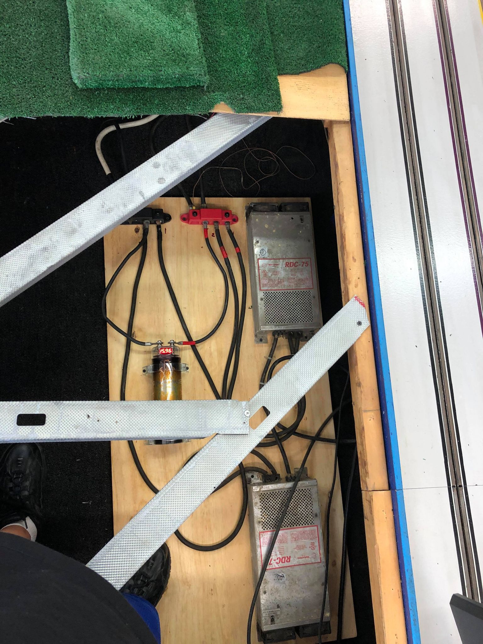
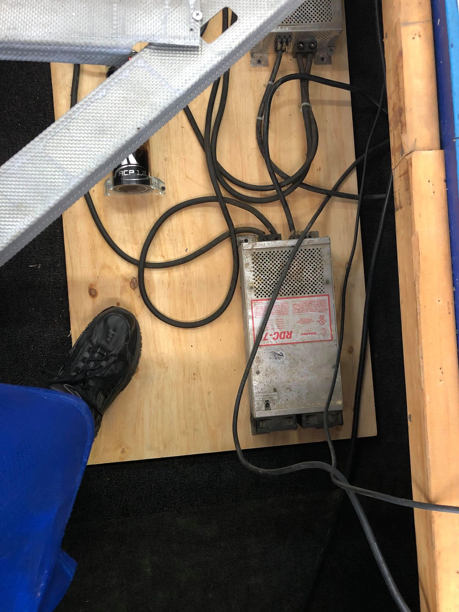
Pictures.... hillclimb was done second, as an upgrade from 75 to 105 Amps w/added cap.
King is 2x 75A w/cap.
- Samiam and NateT like this
Alleged amateur racer.
Mostly just play with lots of cars.
Able to maintain slot cars with a single bound.
Faster than a speeding Womp.
More powerful than a 36D.
#13

Posted 17 January 2022 - 11:48 AM
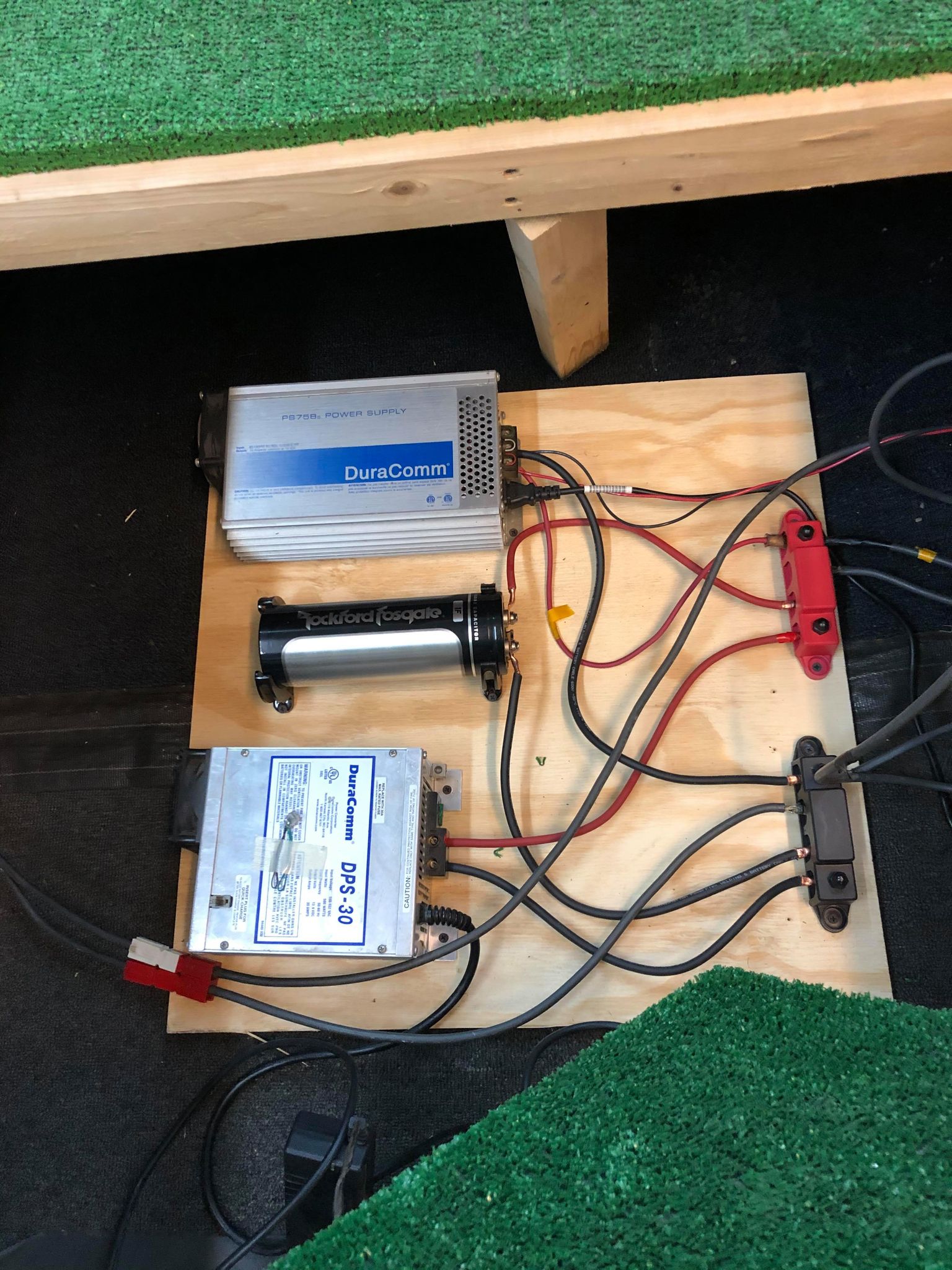
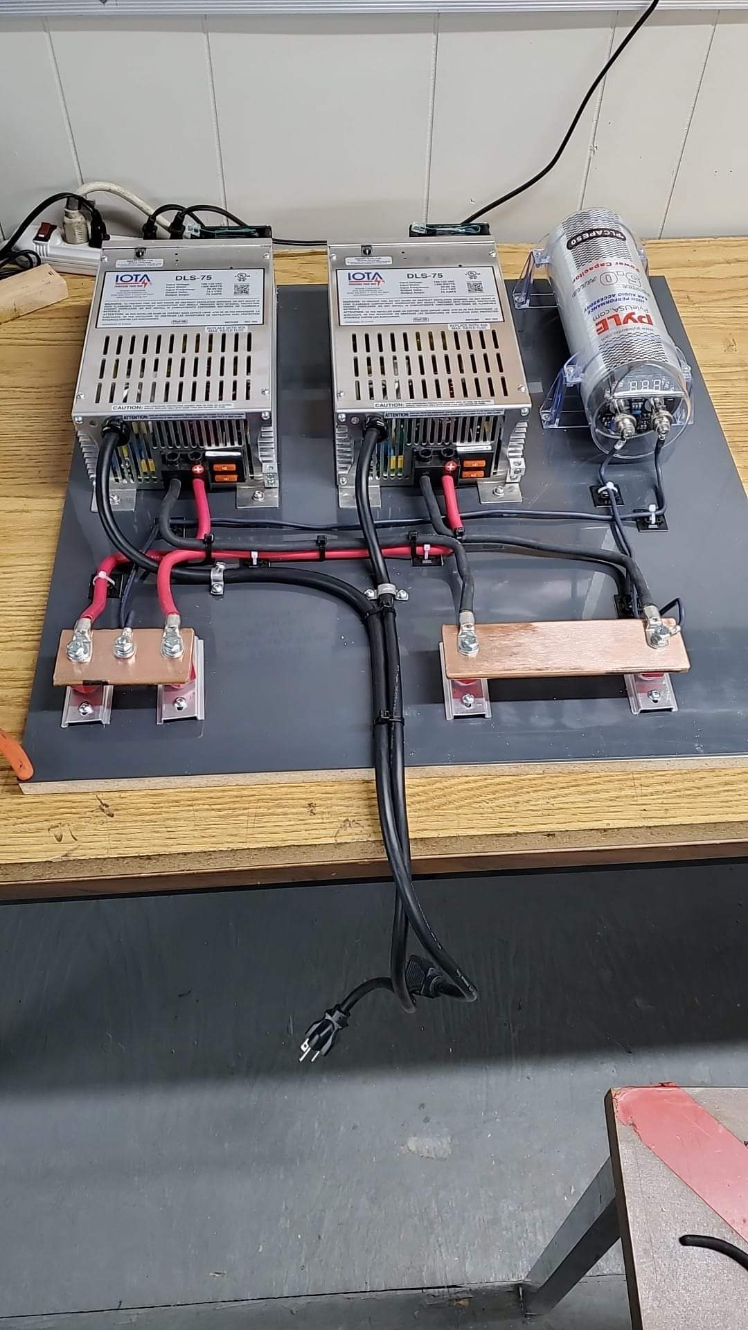
Here is our power supplies and cap before installation.
We are finishing up rebraiding then it will go under the track.
We just need to clean up the taps now.
- NSwanberg, Matt Sheldon and mreibman like this
Nate Talaskavich
NateTalaskavich@gmail.com
Track Owner at ONO Raceway in London Ontario
ONO Slot car club Facebook page
#14

Posted 17 January 2022 - 03:38 PM
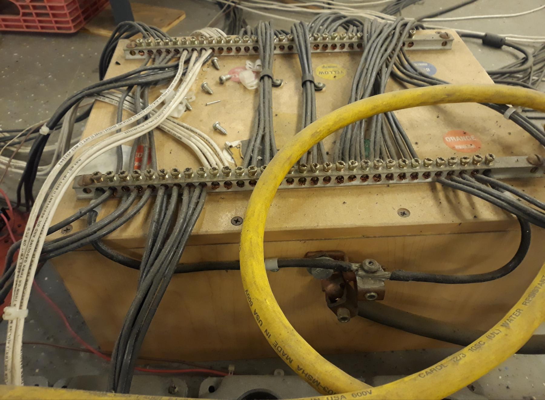
Not sure what your plans are for the taps, but these bars, with square drive set screws, work pretty well.
Shown is the ground side of my wiring.
Mike Swiss
Inventor of the Low CG guide flag 4/20/18
IRRA® Components Committee Chairman
Five-time USRA National Champion (two G7, one G27, two G7 Senior)
Two-time G7 World Champion (1988, 1990), eight G7 main appearances
Eight-time G7 King track single lap world record holder
17B West Ogden Ave., Westmont, IL 60559, (708) 203-8003, mikeswiss86@hotmail.com (also my PayPal address)
Note: Send all USPS packages and mail to: 692 Citadel Drive, Westmont, Illinois 60559
#15

Posted 17 January 2022 - 03:51 PM
Nate Talaskavich
NateTalaskavich@gmail.com
Track Owner at ONO Raceway in London Ontario
ONO Slot car club Facebook page
#16

Posted 17 January 2022 - 05:01 PM
I was afraid you were going to ask that.
Now I have to call my therapist and see if he has an opening this week. Lol
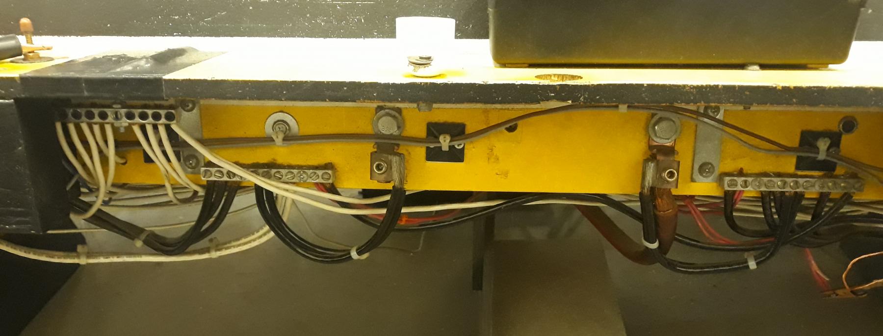
If you have a sharp eye, you can see where I once I had the top 4 lanes segregated from the bottom four. It is now connected as one......unless you go into my rental/birthday party power, which is 8 separate, 8 fully adjustable, circuits.
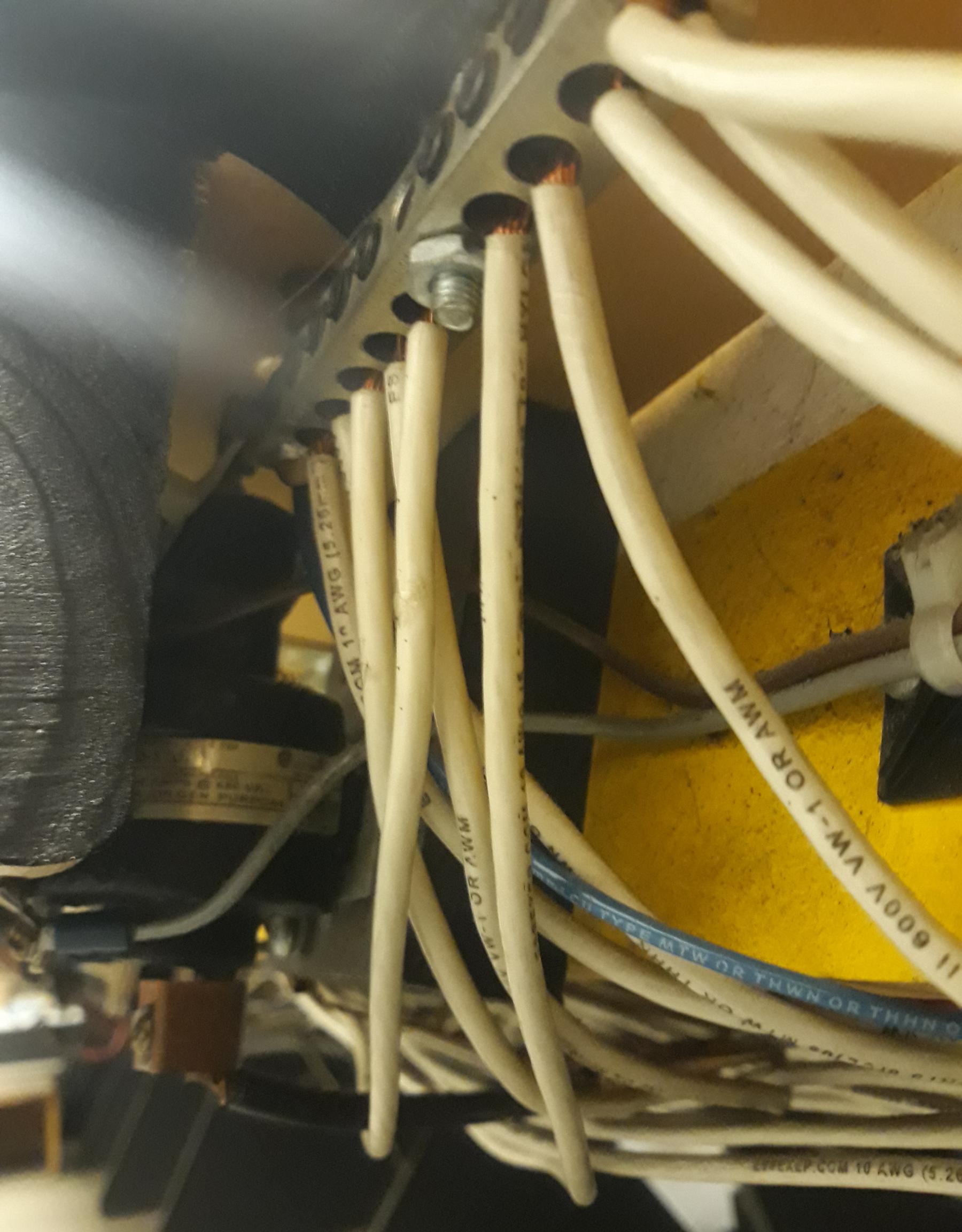
At each control panel, the white post is soldered directly to the 60 amp mercury relays.
The black post is soldered to a cut down piece of those set screw bars, which distributes the ten-10 AWG taps.
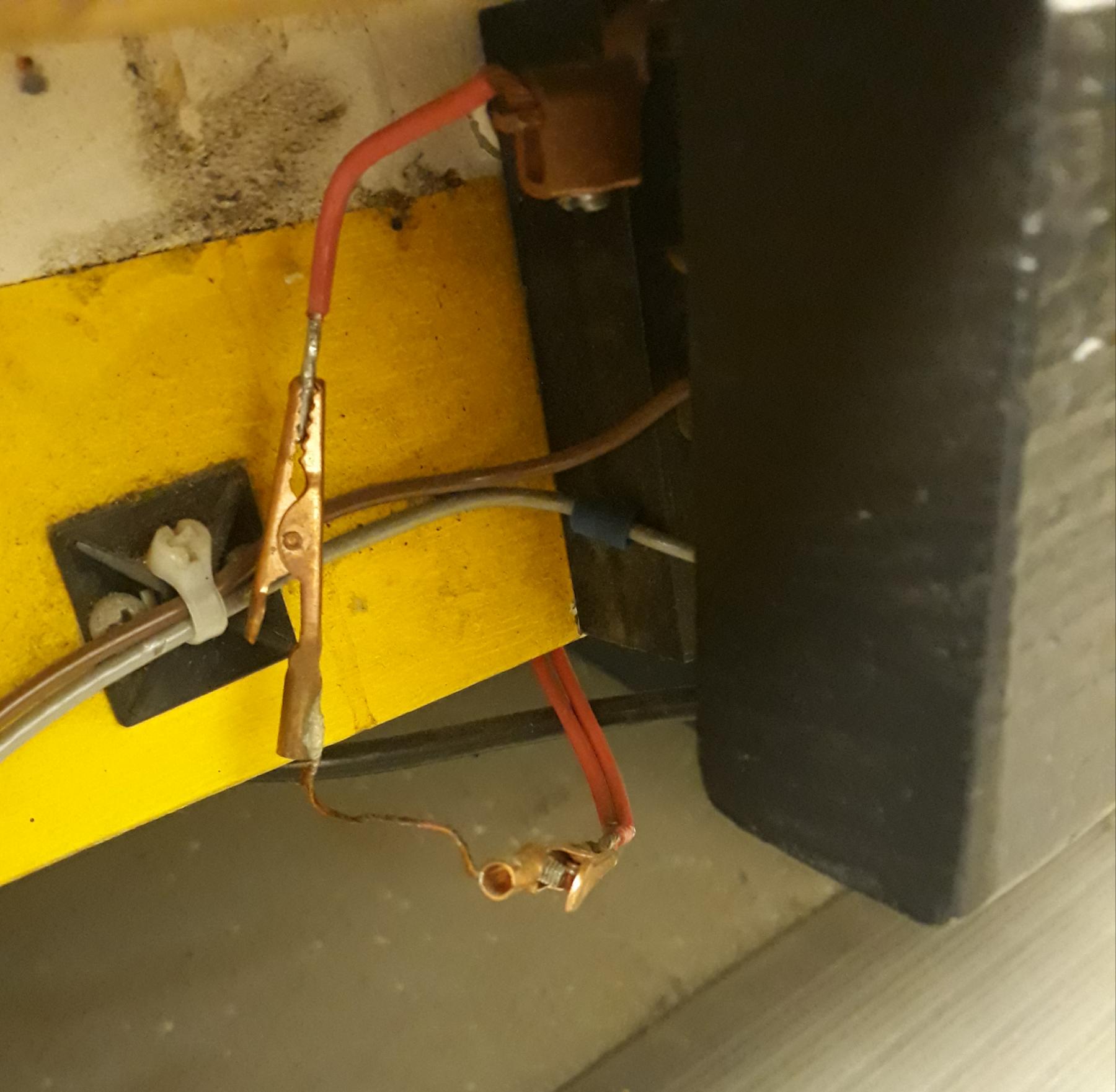
The best part of my wiring.
The fusable links on the brake circuit.
So far, it has saved $4,350 worth of controller repairs on $17,125 worth of electronic controllers.
- Rob Voska, NSwanberg and NateT like this
Mike Swiss
Inventor of the Low CG guide flag 4/20/18
IRRA® Components Committee Chairman
Five-time USRA National Champion (two G7, one G27, two G7 Senior)
Two-time G7 World Champion (1988, 1990), eight G7 main appearances
Eight-time G7 King track single lap world record holder
17B West Ogden Ave., Westmont, IL 60559, (708) 203-8003, mikeswiss86@hotmail.com (also my PayPal address)
Note: Send all USPS packages and mail to: 692 Citadel Drive, Westmont, Illinois 60559
#17

Posted 17 January 2022 - 06:09 PM
That's pretty cool. It gives me a few ideas.
Thank you
- MSwiss likes this
Nate Talaskavich
NateTalaskavich@gmail.com
Track Owner at ONO Raceway in London Ontario
ONO Slot car club Facebook page
#18

Posted 18 January 2022 - 05:53 PM
Here is our power supplies and cap before installation.
We are finishing up rebraiding then it will go under the track.
We just need to clean up the taps now.
I like the copper buss bar. My new setup is basically the same as yours. To get us by initially I put one of these in, however with have a second and capacitor setup next week.
https://www.amazon.c...00?ie=UTF8&th=1
- NateT likes this
Matt Sheldon
Owner - Duffy's SlotCar Raceway (Evans, CO)
#19

Posted 28 January 2022 - 07:58 AM
We were able to get the track finished last night and for the most part, the wiring cleaned up under the track.
after about 1000 test laps, the track worked flawlessly (obviously not under race conditions.)
We did some adjusting and we were .1 difference in lap times from black to red.
More taps coming and thanks to Mike Swiss for the ideas on how to hook up taps efficiently.
- MSwiss, Jason Holmes and NSwanberg like this
Nate Talaskavich
NateTalaskavich@gmail.com
Track Owner at ONO Raceway in London Ontario
ONO Slot car club Facebook page
#20

Posted 28 January 2022 - 10:41 AM
Check out https://powermaxconv...pm3-12v-series/. I use 12v amplifiers that draw up to 100 amps and these hang in there really well.
Charlie McCullough
Charlie's Speed Shop
Kelly Racing Wanna Be
#21

Posted 28 January 2022 - 02:01 PM
Check out https://powermaxconv...pm3-12v-series/. I use 12v amplifiers that draw up to 100 amps and these hang in there really well.
I looked at those but could not find any write up on them as far as quality and durability went for our application. I went with the IOTA as they are the parent company of Rivergate and I do have a few good experiences with their products plus I was able to get a nice discount on 2 of them.
Nate Talaskavich
NateTalaskavich@gmail.com
Track Owner at ONO Raceway in London Ontario
ONO Slot car club Facebook page
#22

Posted 04 February 2022 - 06:14 AM
We had our first race with the new power supply set up and and I was very happy with the performance.
It was consistent from start to finish and across every lane.
I still intend on adding more taps but I would say it was a success plus not having to worry about batteries was a huge bonus for us.
- MSwiss and NSwanberg like this
Nate Talaskavich
NateTalaskavich@gmail.com
Track Owner at ONO Raceway in London Ontario
ONO Slot car club Facebook page
#23

Posted 20 February 2022 - 11:35 AM
I was afraid you were going to ask that.
Now I have to call my therapist and see if he has an opening this week. Lol
20220117_154629.jpg
If you have a sharp eye, you can see where I once I had the top 4 lanes segregated from the bottom four. It is now connected as one......unless you go into my rental/birthday party power, which is 8 separate, 8 fully adjustable, circuits.
20220117_154809.jpg
At each control panel, the white post is soldered directly to the 60 amp mercury relays.
The black post is soldered to a cut down piece of those set screw bars, which distributes the ten-10 AWG taps.
20220117_160916.jpg
The best part of my wiring.
The fusable links on the brake circuit.
So far, it has saved $4,350 worth of controller repairs on $17,125 worth of electronic controllers.
Mike
Aligator clips and a solid piece of solid wire on the brake wire uses the solder to melt as a fusable link?
Is it better than a push button resettable fuse?
Any ideas how many "amps" it takes to melt them?
Sure seems simple. Make up some spares & your in business.
#24

Posted 21 April 2022 - 11:42 AM
I have a King 155 and currently have 2 RDC-90's and a RDC Slot power supplies. I want to do 2 power supplies and a Capacitor. I was at a track in Detriot that had a King track with 2 RDC-Slot power supplies and 2 capacitors. Does that make sense to go with 2 capacitors?


