Jump to content


Photo

Adapting Husting's anglewinder for club/home racing


  • Please log in to reply
46 replies to this topic

#1 Steve Okeefe

Steve Okeefe

    The Independent Scratchbuilder

  • Administrator
  • PipPipPipPipPipPip
  • 1,139 posts
  • Joined: 16-February 06
  • Gender:Male
  • Location:State of Independence

Posted 02 March 2024 - 12:09 AM

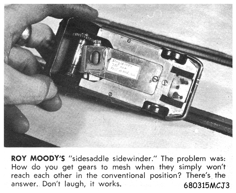
Early 1968 was a marvelous time to be a young slot racer.  People were coming up with all sorts of clever new ideas, most of which didn't work!  :laugh2:  But a few of those ideas did work, and some even had the power to change, overnight, the way we built our cars.  One of the biggest was anglewinder drive.


Gene Husting's simple 1/24 adaptation of something the Midwest 1/32 scale racers had been doing for awhile...


680212 NAMRA132 Moody btm.jpg


680420 CM 132 Nats Weidig Sports Car top.jpg


...caused nothing short of a revolution in slot car chassis design that captures scratchbuilder's imaginations, including mine, even a half century later.


Rick Thigpen sent me a PM and said he wanted to build a "what if" interpretation of the first anglewinder, and I thought it would be fun to go along and build one too.  I had built my own version years ago out of whatever parts I had on hand, but Rick wants to build this one period-correct, so mine would have to be P.C. too.


BTW: Larry Horner is currently building a Retro-style version, so it seems we've got a building party getting started here.  :D


Rick set out his premise in his build thread.  I figured for the sake of novelty mine needed to be a little different, so I chose to build a car adapted to "1/24 club and/or home track" racing.  My premise:


* Early April 1968.  I am an avid east coast scratchbuilder and club racer with a home track.  Both the 110 ft/lap club track and my 78 ft/lap home track are large enough to run 1/24 scale cars, which we do.


* Rick Thigpen (my west coast contact) sent me photos and drawings of something new.  It took four days to get the photos developed and three days to get them to me (by U.S. Mail), so I'm already a week behind..
 

* I can't wait to adapt this crazy new idea I see for use on a smaller club style 1/24 track with sharper, flatter turns, shorter straights and less overall traction.


Club/home track rules include maximum 1/2" wide solid rubber tires running on a dry track surface, so I will not be using a 26 or 25 gauge motor like the commercial racers.  Other than that, the chassis and body will be much the same (angle drive with a stressed motor, wide drop arm, hinged side pans topped off with a Lola T70 coupe body).


Time to start gathering parts... :dance3:


  • Pablo, Fergy, Alchemist and 3 others like this

Steve Okeefe


I build what I likes, and I likes what I build


#2 Alchemist

Alchemist

    Posting Leader

  • Full Member
  • PipPipPipPipPipPipPip
  • 2,692 posts
  • Joined: 11-November 09
  • Gender:Male
  • Location:Far, far away

Posted 02 March 2024 - 02:16 PM

Hi Steve,


I'm looking forward to seeing this exciting project come to fruition as well as viewing progress pictures!


Thank you for sharing!


Ernie


Ernie Layacan

#3 Steve Okeefe

Steve Okeefe

    The Independent Scratchbuilder

  • Administrator
  • PipPipPipPipPipPip
  • 1,139 posts
  • Joined: 16-February 06
  • Gender:Male
  • Location:State of Independence

Posted 02 March 2024 - 11:53 PM

Hi Ernie, hope you enjoy the show... including all the pictures. :D


So let's get this project started.  First thing is the motor can, as it is literally part of the chassis in addition to being part of the motor.


I've chosen the common FT-16D can for two reasons:


1. It has a built-in separate bearing carrier that makes it possible to replace the bearing from the outside (the older FT-16 can does not have a separate bearing carrier at all).


2. The separate bearing carrier on the FT-16D is made of brass, which can be soldered easily (the bearing carrier on the 68 Mabuchi can is aluminum, which is very difficult to solder).


FT-16D cans are typically painted, but a few are nickel plated or (rarely) chrome plated.  Remember the can is part of the chassis, so it's very important that the solder stick well with a minimum of hassle.  Scraping off paint (or worse, chrome plating) is a hassle.  Clearly, the easiest one to work with is nickel plated, so that's my choice.


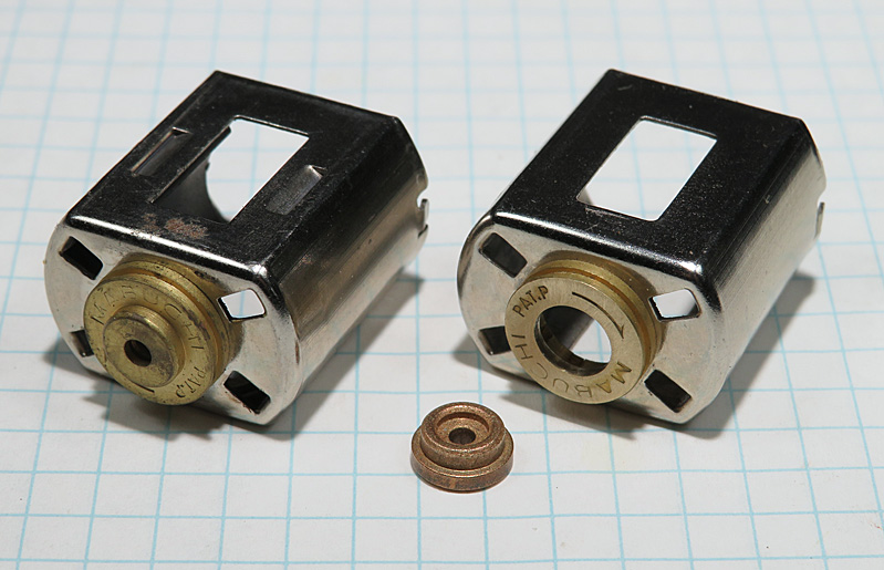
Here's a couple of nickel plated FT-16D cans:


001 Can modification.jpg


The can on the left is completely stock.  The one on the right has had its internal gimbal bushing and retainer removed, and the hole opened up to fit the Champion bushing (sitting next to it).


Here's the same two cans, but with the bushing in place:


002 Can & Bushing.jpg


Looks almost stock...  B:)


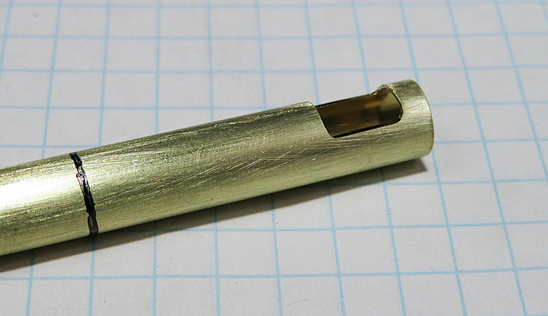
Now the 9/32" axle tube:


003 Clearance hole.jpg


Filing out the notch is much easier if you do it before cutting the tube to length!  I can't tell you how many times I've made that mistake... :dash2:   :laugh2:


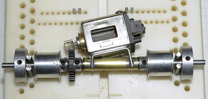
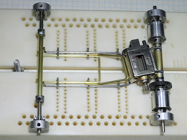
The rest is simply snuggling up the motor to the tube and the gear (here it's at about a 13 degree angle), keeping it reasonably well centered in the chassis, bending up the top and bottom braces and soldering them in:


004 Motor & Axle Assy.jpg


Some notes about positioning the motor, spur gear and braces:


1. I made the braces as wide as practical and arranged them so they attach near the top and bottom of the motor can. As a result the top brace goes downward to the axle tube, and the bottom brace goes upward to the axle tube.  I did this in order to achieve the greatest possible mechanical advantage for the solder joints, making the tail end of the chassis as strong as possible.


2. I made sure to provide ample space for the spur gear between the wheel and the axle bearing, so that the gear can be spaced side to side to adjust the gear mesh.  With the motor soldered into the chassis, there's no other way to adjust the gear mesh.


3. The final setup will include a spur gear that is larger than the jig wheels, so I'm using "Rick's Gear Rule" to build the chassis.  The spur gear in the photo is 34 teeth (48 pitch) and is the same diameter as the jig wheels, so that everything sits flat on the jig block.  The car in race trim will use a 36 tooth gear.  How can I set the gear mesh (and build the chassis) without using a 36 tooth gear?


Rick's Gear Rule states that equal total numbers of teeth will provide equal gear mesh.  For example: The spur gear in the photo is 34 teeth and the pinion is 9 teeth, for a total of 43 teeth.  When I later install a 36 tooth spur gear and use a 7 tooth pinion, the total number of teeth will still be 43, so the gear mesh will be the same.


Disclaimer: Because of manufacturing tolerances and minor differences in pinion gear tooth shape, the mesh equivalency is not always 100% perfect, but it's close enough to work quite well.  :good:  Besides, that's another reason I provided plenty of room to space the spur gear side to side to adjust gear mesh.


Next up: Main rails.


  • don.siegel, Pablo and Tex like this

Steve Okeefe


I build what I likes, and I likes what I build


#4 Larry Horner

Larry Horner

    On The Lead Lap

  • Full Member
  • PipPipPipPip
  • 458 posts
  • Joined: 18-March 17
  • Gender:Male
  • Location:San Francisco

Posted 03 March 2024 - 07:25 PM

I feel so guilty seeing all the motor work that you and Rick put in!  :shok:


#5 dc-65x

dc-65x

    Grand Champion Poster

  • Subscriber
  • PipPipPipPipPipPipPipPip
  • 6,956 posts
  • Joined: 14-February 06
  • Gender:Male
  • Location:Captain Rick: The only vintage slot car nut in SW Oregon?

Posted 03 March 2024 - 08:07 PM

No need to feel guilty Larry. Steve and I like to fiddle with motors. Painting bodies.......not so much!     :shok:  :D


Looking good Steve. It's nice to have the motor and rear axle locked down. Looking forward to the rest of your build.


  • Pablo and Larry Horner like this

Rick Thigpen
Check out Steve Okeefe's great web site at its new home here at Slotblog:
The Independent Scratchbuilder
There's much more to come...


#6 Pablo

Pablo

    Builder

  • Administrator
  • PipPipPipPipPipPipPipPip
  • 18,443 posts
  • Joined: 20-February 06
  • Gender:Male
  • Location:Cleveland, Tennessee

Posted 03 March 2024 - 09:46 PM

I love watching experts fiddle  :D


  • Larry Horner likes this

Paul Wolcott


#7 Steve Okeefe

Steve Okeefe

    The Independent Scratchbuilder

  • Administrator
  • PipPipPipPipPipPip
  • 1,139 posts
  • Joined: 16-February 06
  • Gender:Male
  • Location:State of Independence

Posted 04 March 2024 - 12:17 AM

No worries, Larry, Rick is right; we just like to... except for the paint. :laugh2:


Steve Okeefe


I build what I likes, and I likes what I build


#8 Steve Okeefe

Steve Okeefe

    The Independent Scratchbuilder

  • Administrator
  • PipPipPipPipPipPip
  • 1,139 posts
  • Joined: 16-February 06
  • Gender:Male
  • Location:State of Independence

Posted 04 March 2024 - 11:29 PM

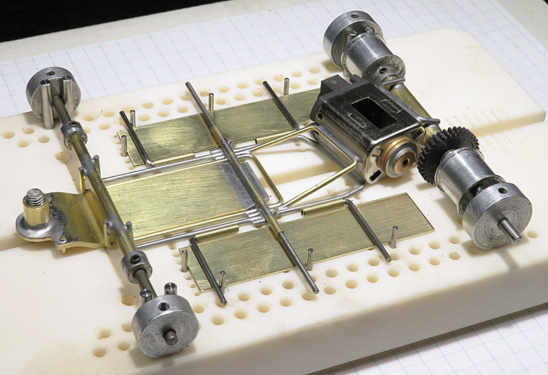
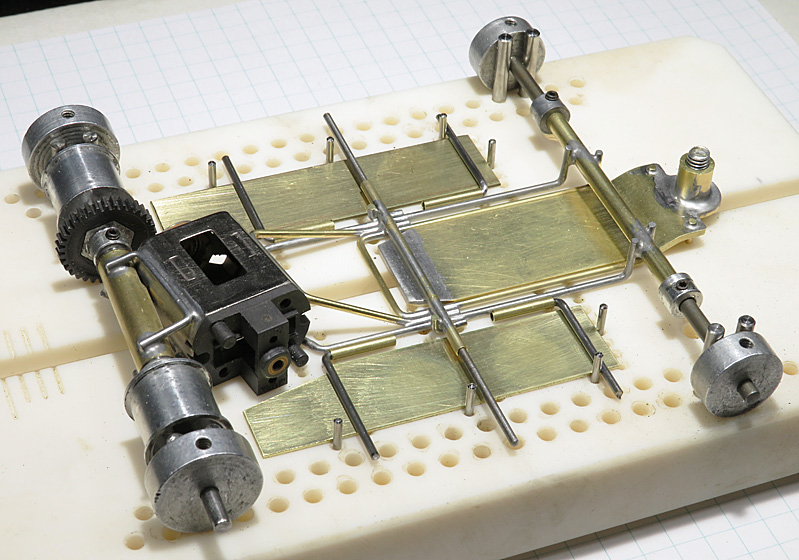
Time to build the center section (if you want to call it that). :unknw:


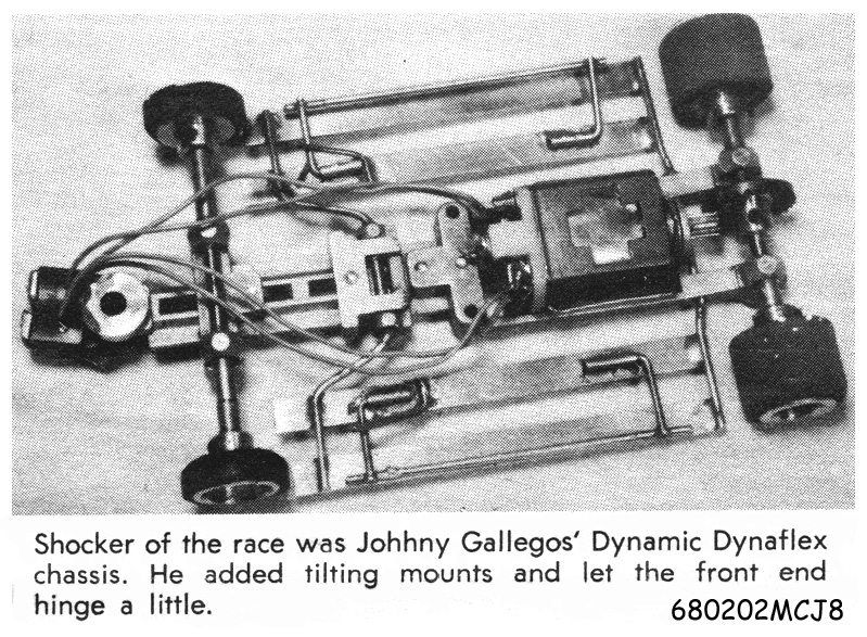
Gene's original anglewinder chassis was different from current 1968 design standards in more ways than just having an angle drive.  With the front axle attached directly to the drop arm it was, from a functional standpoint, more like a Dynamic Dyna-Flex:


680127 3rd CMRA Gallegos Coupe top.jpg


Conventional front ends (solid, live axle and set screw wheels, with the axle in a tube attached to the main rails) were working just fine on other chassis, so I figured that's the way I wanted to go.  Besides, the more stuffy racers down at the club rather frown on pinhole front wheels. :big_boss:   Something about how it's hard to put wheel inserts in them.  :mosking:


At any rate, Gene's design leaves the chassis with very little flex, so I decided to stick with only two rails, but make one piano wire and the other brass rod.


In addition, because one is brass and the other steel. I don't want the two rails right next to each other with no spacing.  The difference in expansion rates, particularly if the rails end up soldered together (intentionally or not), will in many cases cause them to warp to an unpredictable degree.


Here's what I came up with:


005 Pieces Parts.jpg


I put the piano wire rail on the outside because that's where the side pan hinge tubes will be attached, and piano wire is definitely stronger than a brass rail.


The smaller brass rod brace (upper right in the photo) was a real bear to make. :dash2:   It took more time and effort than any other single part of the chassis.


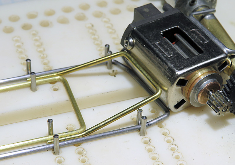
Here's how it all fits together:


006 Main Rails.jpg


007 Main Rails a.jpg


008 Main Rails b.jpg


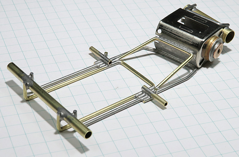
Next step was to solder it all together, add the drop arm hinge tubes and a pair of small braces along with the front end cross piece (hidden behind the front axle tube):


009 Center Section.jpg


Light, strong and compact; I'm happy with it.  ^_^


The drop arm and side pans.are next.  :D


  • dc-65x, Pablo, Slot Car Rod and 2 others like this

Steve Okeefe


I build what I likes, and I likes what I build


#9 Larry Horner

Larry Horner

    On The Lead Lap

  • Full Member
  • PipPipPipPip
  • 458 posts
  • Joined: 18-March 17
  • Gender:Male
  • Location:San Francisco

Posted 05 March 2024 - 12:26 AM

Very clean and tidy! And you did another of those front top braces where they meet the frame rails at the same fore/aft location. I made two attempts at that and bailed. It looks so simple when you see it but it's so not!


#10 Steve Okeefe

Steve Okeefe

    The Independent Scratchbuilder

  • Administrator
  • PipPipPipPipPipPip
  • 1,139 posts
  • Joined: 16-February 06
  • Gender:Male
  • Location:State of Independence

Posted 06 March 2024 - 07:46 PM

Before the end of 1967, drop arms were generally built up out of brass rod and tube, and occasionally a little piano wire.  They started out in 1966 with only two or three pieces, and eventually ended up with a dozen or more soldered together to make a slab.


At the end of 1967, builders began using a 3/4" wide strip of 1/16" thick brass for their drop arm, but still had to figure out how to build the guide post mount up and forward of the brass strip.  That was probably the most difficult part of building a drop arm; as there were almost as many different designs as there were builders.


In April of 1968, just days before the first anglewinder race, Cobra began advertising a "new 1/16 plate drop arm" in Model Car Journal.  There was no picture so I don't know what they looked like, but on the same page there was a picture of Jerry Brady's new race winning "no motor bracket" inline chassis, complete with a one piece, 1/16 thick plate drop arm.


I'm slow about these things, so Rick Thigpen reminded me he had pointed this all out four years ago.   :dash2:


Well, if Jerry Brady could make his one piece drop arm in March 1968, I could make mine in April:


010 Drop arm.jpg


7/8" wide.  The small pegs on the front (one is hidden) are guide stops, and the tall guide post tube will be cut down later as required to fit under the nose of the body.


Here is the drop arm installed in the chassis.  It fits just so:


011 Center w drop arm.jpg


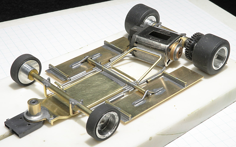
Now the 3/4" by .032" side pans, hinge tubes and hinge arms are cut. bent and fitted:


012 Pans Left.jpg


013 Pans Right.jpg


The final form is beginning to take shape.  :dance3:  Now I need to solder all this up and add some down stops and pin tubes..


  • dc-65x, Tex, Samiam and 2 others like this

Steve Okeefe


I build what I likes, and I likes what I build


#11 Larry Horner

Larry Horner

    On The Lead Lap

  • Full Member
  • PipPipPipPip
  • 458 posts
  • Joined: 18-March 17
  • Gender:Male
  • Location:San Francisco

Posted 06 March 2024 - 11:52 PM

You might not have even needed it but good to see the beveled drop-arm tradition carried on. I love the detail of the one pan being mitered to clear the end bell ... very cool!


#12 Pablo

Pablo

    Builder

  • Administrator
  • PipPipPipPipPipPipPipPip
  • 18,443 posts
  • Joined: 20-February 06
  • Gender:Male
  • Location:Cleveland, Tennessee

Posted 07 March 2024 - 07:58 AM

Very strong looking and dead sexy  :heart:  :heart:  :heart:  :heart:  :heart:


Paul Wolcott


#13 Eddie Fleming

Eddie Fleming

    Posting Leader

  • Subscriber
  • PipPipPipPipPipPipPip
  • 2,899 posts
  • Joined: 27-April 14
  • Gender:Male
  • Location:Fayetteville, GA USA

Posted 07 March 2024 - 08:03 AM

I would not have called it sexy, but whatever cranks your tractor. i guess? 


Very strong looking and dead sexy  :heart:  :heart:  :heart:  :heart:  :heart:


Eddie Fleming

#14 Steve Okeefe

Steve Okeefe

    The Independent Scratchbuilder

  • Administrator
  • PipPipPipPipPipPip
  • 1,139 posts
  • Joined: 16-February 06
  • Gender:Male
  • Location:State of Independence

Posted 08 March 2024 - 09:38 PM

First up is the drop arm down stop.  When drop arms were made out of four or five pieces of 1/16" brass rod, soldering a down stop across several or all of them was no problem at all.  Later, when trying to solder a down stop across the middle of a 3/4 " or 1" wide slab of 1/16" thick brass, builders found out quickly it is a bit more problematic.


Temporarily raising the drop arm, and if necessary the whole chassis up off the jig block with pieces of 1/16" rod or piano wire slid cross-ways underneath will help.  That way you're not trying to heat up the jig block as well as the drop arm.  But it still takes a LOT of heat to melt the solder and produce a neat and clean joint.


A clever workaround is to solder the down stop at the edge of the drop arm; that way there's a lot less of the slab to heat up.  It works, too!  :good:


A variation on this is to drill a 1/16" hole near the edge of the drop arm, bend a small piece of 1/16" brass rod into an "L" shape, and solder it into the hole, like this:


014 DA  down stop.jpg


Next are the side pan hinge tubes.  Mine are flush with the bottom of the chassis, which requires the hinge arms be "kinked" to rise up and lay flat on top of the .032" thick pan.


In this case the pans are so close to the hinge tubes I also had to recess the edges of the pans to fit the hinge arm.  Since I'm planning on building only one of these, I will take the time to bend the hinge arms and recess the pans, but if I were building several, I would just raise the hinge tubes up.


Once the hinge arms are soldered down to the pans, the body mount pin tubes are soldered on top.


015 Chassis Left.jpg


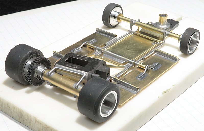
On this chassis the drop arm hinge pin is extended out on both sides to act as a pan up and (with the addition of the shackles) down stop.


The shackles themselves are fairly easy to make.  I normally use .047" piano wire because it's plenty strong enough and is much easier to bend than 1/16".  To make them you take a piece of .047" and mark it at 1/4", 1/2", 3/4" and 1".  Cut the piece off at the 1" mark and bend at the other three marks.  Do this twice, obviously.  :wacko2:


Keep the bends in line so the shackles lay flat, and make both parts the same height, and of course tall enough to reach the pans when laid over the pan hanger!  This process works best if you make one shackle the correct height, and then make the other shackle a duplicate of the first.  :dance3:


Position the shackles on the pans and solder them down.  Soldering these shackles to the middle of an .032" thick pan is MUCH easier than soldering a down stop in the middle of a 1/16" thick drop arm!


016 Chassis Right.jpg


Here's a view of the bottom of the completed chassis.  Look carefully and you can see the down stop hole in the drop arm.


017 Chassis Bottom.jpg


Next up is mounting the body.  :D


  • Jencar17, Tex, Half Fast and 6 others like this

Steve Okeefe


I build what I likes, and I likes what I build


#15 Martin

Martin

    Posting Leader

  • Full Member
  • PipPipPipPipPipPipPip
  • 4,193 posts
  • Joined: 22-February 09
  • Gender:Male
  • Location:US

Posted 09 March 2024 - 11:06 AM

That's a tidy clean way to locate the down stop, strong too  :good: Thanks for pointing that detail out. Nice build Steve.


Martin Windmill

#16 Steve Okeefe

Steve Okeefe

    The Independent Scratchbuilder

  • Administrator
  • PipPipPipPipPipPip
  • 1,139 posts
  • Joined: 16-February 06
  • Gender:Male
  • Location:State of Independence

Posted 09 March 2024 - 01:04 PM

Thanks Martin! :D


Simple as it is, that drop arm down stop detail has worked very well so far, on several chassis.


Try locating it under the front axle tube; it can work as an up stop as well.  :good:


Steve Okeefe


I build what I likes, and I likes what I build


#17 Martin

Martin

    Posting Leader

  • Full Member
  • PipPipPipPipPipPipPip
  • 4,193 posts
  • Joined: 22-February 09
  • Gender:Male
  • Location:US

Posted 09 March 2024 - 02:40 PM

I do love design that has one item do more that one job  :victory:


Martin Windmill

#18 Larry Horner

Larry Horner

    On The Lead Lap

  • Full Member
  • PipPipPipPip
  • 458 posts
  • Joined: 18-March 17
  • Gender:Male
  • Location:San Francisco

Posted 09 March 2024 - 03:47 PM

Such a clean and elegant looking design! So Lola T70 or are you going to go in a whole other direction?


#19 Steve Okeefe

Steve Okeefe

    The Independent Scratchbuilder

  • Administrator
  • PipPipPipPipPipPip
  • 1,139 posts
  • Joined: 16-February 06
  • Gender:Male
  • Location:State of Independence

Posted 10 March 2024 - 09:09 PM

Lola T70 coupe it is. :good:


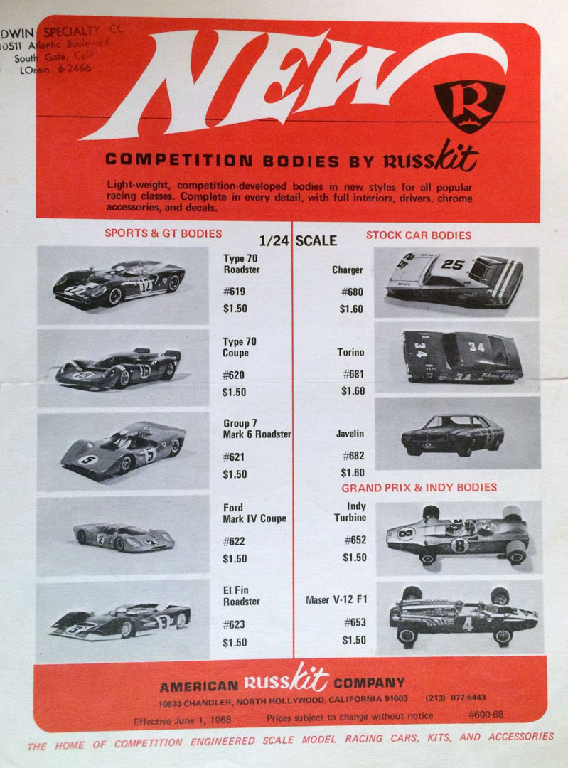
In early 1968, Russkit produced what was to be their last series of bodies.  One of them, number 620, was a Lola T70 coupe.


205 Russkit 6805 Retail Flyer.jpg


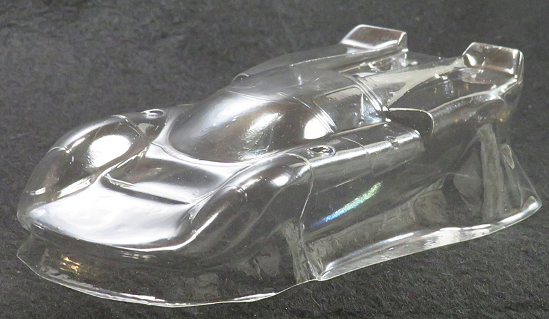
The body I will be using is a lexan repop, not a vintage original, which was most likely made of butyrate:


201 Lola T70 Coupe Left.jpg


Unfortunately, I have no idea who actually pulled it, or when (aside from a number "2" in the recess where the injector stacks go, there are no markings).


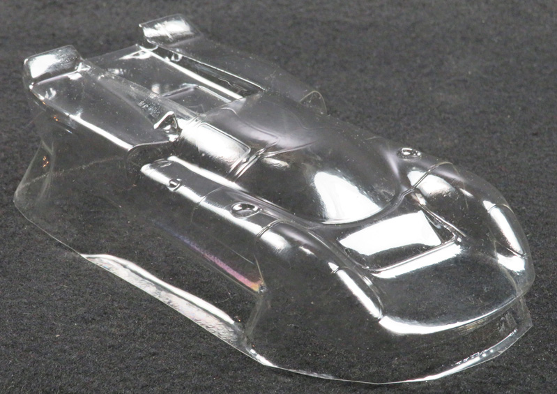
I didn't even know it was a Russkit repop until Rick helped me identify it.  The giveaway was that small NACA style duct (or scoop) just behind the driver's window:


202 Lola T70 Coupe Right.jpg


That scoop doesn't appear in any photo of any prototype Lola T70 coupe I've ever seen (right side or left side).  :unknw:


Anyway, I cut and trimmed the body and fiddled with it for an hour or so (it wasn't the highest quality repop you ever saw), and manged to get it on the chassis.


As a reminder, no matter what Russkit says, this is not a low, wide and long "handling body".  :huh:


203 Body Mounted Left.jpg


Here's a side view:


204 Body Mounted Side.jpg


I wanted to keep all of the radiator intake detail, plus be able to fit the guide post under the body, so the nose and front fenders are a bit higher up than they might otherwise be on a commercial pro car.  Nevertheless the body sits level on the chassis, so I'm happy with it.


Next up, the horsepower.  :D

.


  • Pablo, Jencar17, Bill from NH and 2 others like this

Steve Okeefe


I build what I likes, and I likes what I build


#20 Flathead

Flathead

    Mid-Pack Racer

  • Full Member
  • PipPipPip
  • 172 posts
  • Joined: 01-January 10
  • Gender:Male
  • Location:London, England

Posted 11 March 2024 - 03:31 AM

Steve I would think that the body you have is the Booth repop especially as it's in lexan. Photo from Booth Machine website;

IMG_8902.jpeg

Roger Schmitt has recently found the original Russkit buck for this body along with others (dune buggy, mclaren mk6) in the basement at Parma, so hopefully, it may be available again soon

Great build, by the way


Lee Welch
Wanted; MPC Scarab windshield.

#21 Steve Okeefe

Steve Okeefe

    The Independent Scratchbuilder

  • Administrator
  • PipPipPipPipPipPip
  • 1,139 posts
  • Joined: 16-February 06
  • Gender:Male
  • Location:State of Independence

Posted 11 March 2024 - 12:47 PM

Thanks, Lee! :D


Could be; it sure does look the same, right down to the NACA duct, the long tail and the (relatively) short nose.


I will be sure to keep an eye out at the Mid America website!  :good:


Steve Okeefe


I build what I likes, and I likes what I build


#22 Steve Okeefe

Steve Okeefe

    The Independent Scratchbuilder

  • Administrator
  • PipPipPipPipPipPip
  • 1,139 posts
  • Joined: 16-February 06
  • Gender:Male
  • Location:State of Independence

Posted 14 March 2024 - 09:17 PM

Time to build up a motor for this club/home racer.


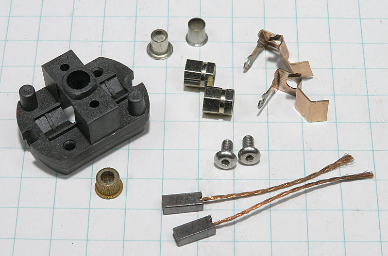
First the endbell. Here are the parts;


301 Endbell Parts.jpg


Because the Mura endbell is made of a higher melting temperature plastic than a stock Mabuchi white, and because this will be a club/home motor (not a 25 gauge commercial fire-breathing monster), I don't anticipate needing to "bulletproof" the endbell.  Post protectors yes, full brush plates and bolted-in endbell bearing, no.


Before anything else, drill the endbell-to-can mounting holes, then tap them and the brush gear mounting holes for 2-56 machine screws.


I'm going to use 26D brushes, but the brush holders don't fit well in a 16D endbell, so I will have to modify them slightly.  They're a few thousandths too wide and several thousandths too long.  A small file will quickly take care of that.  The idea is the leave enough space between the installed brush holders to fit the commutator.


302 Brush Holders.jpg


I think I remember reading somewhere a long time ago that Bill Steube Sr., when soldering the brush holders to their retaining clips, would drill a hole in the brush holder clip to allow solder to pass through and flow around the brush holder.


Whether or not it was Bill Steube Sr. it struck me as a really good idea, so I drilled my own holes and soldered the brush holders to the clips.  If you tin both the holders and the clips first, you can go very quickly and be done before the heat starts to damage the endbell plastic:


303 Solder Clips.jpg


Install the endbell bearing and post protectors.  For period correct-ness I use fillister head screws to mount the brush gear.  Done!


304 EB Complete.jpg


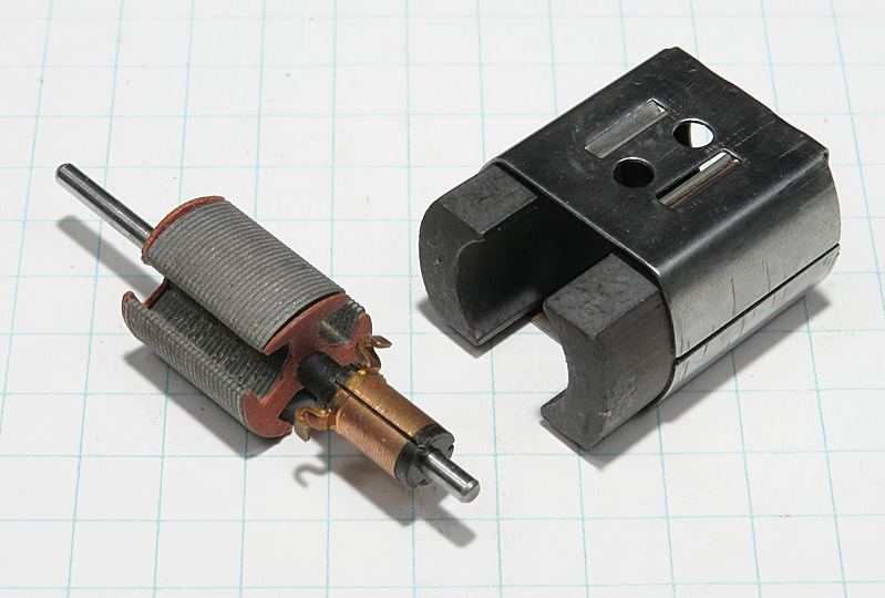
Here are the magnets and shim I will be using.  I will be winding the armature using a Tradeship blank with (I believe) a Kirkwood commutator:


305 Arm, Mags & Shim.jpg


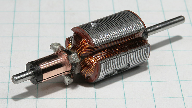
After prepping the blank, which included setting the comm timing at 10 degrees, I wound it with 65 turns of 29 gauge wire.


To finish, I soldered the tabs with 95-5, tied the wires with unwaxed dental floss, and potted the whole thing with a coat of hardware store epoxy.


When the epoxy had cured, I static balanced the arm, cleaned up the pole faces and cut the comm:


306 Finished arm.jpg


Ready to rock-and-roll on the club track or my home track.  :dance3:


Next up, putting all the pieces together. :D


  • dc-65x, Jencar17, Tex and 3 others like this

Steve Okeefe


I build what I likes, and I likes what I build


#23 Bill from NH

Bill from NH

    Age scrubs away speed!

  • Full Member
  • PipPipPipPipPipPipPipPip
  • 14,727 posts
  • Joined: 02-August 07
  • Gender:Male
  • Location:New Boston, NH

Posted 14 March 2024 - 10:24 PM

The arm looks good Steve.


Bill Fernald
 
I intend to live forever!  So far, so good.  :laugh2:  :laugh2: 

#24 Steve Okeefe

Steve Okeefe

    The Independent Scratchbuilder

  • Administrator
  • PipPipPipPipPipPip
  • 1,139 posts
  • Joined: 16-February 06
  • Gender:Male
  • Location:State of Independence

Posted 15 March 2024 - 12:03 AM

Thanks Bill.  :)


I'm hoping this combination, geared numerically high, will give me good all around performance on a club or home track with short straights, sharp flat turns and limited traction.  :good:


Steve Okeefe


I build what I likes, and I likes what I build


#25 Pablo

Pablo

    Builder

  • Administrator
  • PipPipPipPipPipPipPipPip
  • 18,443 posts
  • Joined: 20-February 06
  • Gender:Male
  • Location:Cleveland, Tennessee

Posted 15 March 2024 - 07:50 AM

:heart:  :heart:  :heart:  :heart:  :heart:


Paul Wolcott


Electric Dreams Online Shop