Jump to content


Photo

MDC Bat chronicles


29 replies to this topic

#1 Martin

Martin

    Posting Leader

  • Full Member
  • PipPipPipPipPipPipPip
  • 4,180 posts
  • Joined: 22-February 09
  • Gender:Male
  • Location:US

Posted 30 October 2024 - 09:52 PM

     MDC Bat Chronicles
 
Page 1
By 1966 MDC had already made several slot cars and products and was ready to take a chance on an original RTR car.   The Bat.
"After all, we make metal dies. We can make the injection molded body and the cast chassis in house, no problem, let's do it"
Management took a chance on this endeavor, the market was hot. They did not want to miss out on a chance to make a profit. The company split the work, the body to one group, more art based and the chassis to another group more focused on engineering.
The slot car business was moving fast, so they really had to get on this project if they were to get to market on time.
It was called the Bat (as kids were buying everything Bat). The guys were given a few workshop restrictions. It could not slow down or interfere with work already in house, and had to be done after hours. No problem for this enthusiastic group of skilled craft people that had been exposed to the slot car craze.
A few evenings and weekends and we will be in the RTR slot car market, making money and getting a big bonus from the boss, maybe?
Well as you would expect it took longer than they had thought, but it was getting done.
The art team made ads and art work and even a great looking box that the ready to run finished car would be sold in. This excited and motivated the others involved in the project.
First to finish were the guys making the body, a sports car with a high V shaped tail and a swoopy clear canopy.
The tooling for the canopy was not quite ready,but the body tooling was and good enough to start a small production test run of injection molded bodies in red and black.
Things were looking great.  (to be continued)  
 
This is the way I imagined the events could of taking place almost 60 years ago. 
This took some friends and I on a journey of continuing where MDC left off. 
I wanted to know why the product never made it to market. So I read all, and studied every pic available. Then set about to make the best MDC Bat using original and reimagined parts. 
I hope you will stick around for page 2 and beyond. 
 
Happy Halloween :)
   

  • Gene/ZR1, Old Pilot and Larry Horner like this
Martin Windmill


#2 don.siegel

don.siegel

    Grand Champion Poster

  • Subscriber
  • PipPipPipPipPipPipPipPip
  • 5,816 posts
  • Joined: 17-February 06
  • Gender:Male
  • Location:Paris, France

Posted 31 October 2024 - 03:55 AM

Good story Martin. 


Looking forward to following the trail. 


Don 


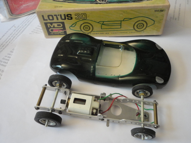
PS: they had already released a few slot cars, however, with vac-formed bodies. 


MDC Lotus 30-2.jpg


  • Gene/ZR1 and Old Pilot like this

#3 Martin

Martin

    Posting Leader

  • Full Member
  • PipPipPipPipPipPipPip
  • 4,180 posts
  • Joined: 22-February 09
  • Gender:Male
  • Location:US

Posted 31 October 2024 - 05:37 AM

Thanks Don, a work in progress.  :good:

First line now modified to say By 1966 MDC had already made several slot cars and products and was ready to take a chance on an original RTR car. The Bat.


The RTR Bat was quite a bit more involved of course with its original injection molded body and die cast chassis. 

Stay tuned, much more to come. 

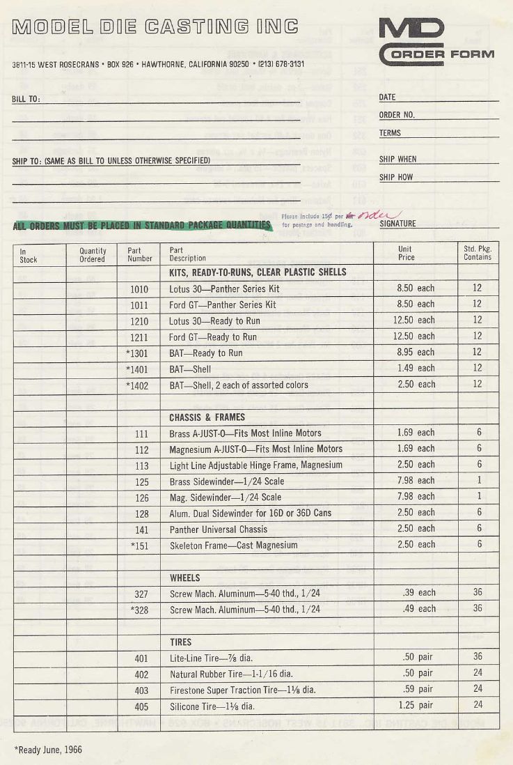
Here is a list of what MDC was advertising at the time.


MDC9.jpg


Notice part number 151 The Skeleton frame. Saying ready June 1966. 


  • Gene/ZR1 and Old Pilot like this
Martin Windmill

#4 Martin

Martin

    Posting Leader

  • Full Member
  • PipPipPipPipPipPipPip
  • 4,180 posts
  • Joined: 22-February 09
  • Gender:Male
  • Location:US

Posted 31 October 2024 - 10:16 AM

Bats and Skeleton frame how appropriate for Halloween. 


MDC4.jpg


Page 2

Staying focused on the story behind the Bat and the Skeleton frame.


Once the chassis tooling was done, some die cast samples were made and checked to see if all was good. "Is it ready for production?"
Motor mounting was a good fit, although there was some concern that the can drive motor side was not held well enough, screws holding the end bell being on the opposite side of the drive. But the engineers maintain if the big bearing hole was designed slightly
over center and a tight fit it would be fine.
 
Next up is to check gearing, well it's a fixed center to center so no adjustment here. But that was common at this time on other brands. As long as the tooth count is the same there can be some variation in gear ratios." O.K., tic that box".
 
Next up, the drop arm. It was designed for a wire drop arm, as we had seen that used on several other brands, it was cheap to make and the management liked that.
 
We actually did try mounting the guide directly to the chassis's up-stop but it was placed too high for that to work, "so start making wire drop arms guys".
 
The fact that the drop arm up-stop was there meant we could not use a one piece axle that went all the way from one wheel to another, we have to have fixed stub axles pressed into the chassis and a free spinning wheel, "O.K. that works."
 
Rear axle would be reamed to accept an 1/8" axle and no bushing used.To keep costs down.
 
Lets see how that body looks mounted on the freshly made chassis.
 
"Oh no, who punched these holes in the body? This does not look good guys.
Cut the cast body pins off that were designed to fit the holes in the body, I guess we can use screws. Screws? Somebody said we are screwed. I tried that, and the chassis will not let the body sit low enough on the chassis, it runs into the interior base."
 
What's the solution here? Time is wasting and the hobbies' tastes and wants are changing every day.
"How about we cut the interior base out, that might work but still the body mount holes are not correct. Scrap 'em, the kids want vac-u-formed bodies now anyway. O.K. we can do that."
 
A vac-u-form tool was already made, front bumper, canopy and all in one, but with the body mount holes eliminated. It was decided to sell these clear bodies at this time to try and recoup some of the costs of the chassis and body tooling. 
 
That works for now. The management wants to know who screwed up here. A lot of finger pointing at this stage and it didn't really matter anyway. The day of big wheels, hard body slot cars were gone. The kids wanted speed at the track. Low, wide and fast, that was what was selling now. 
 
The Bat RTR project just took too long and there were just too many issues to make it worthwhile.      

  • Gene/ZR1 and SpeedyNH like this
Martin Windmill

#5 Martin

Martin

    Posting Leader

  • Full Member
  • PipPipPipPipPipPipPip
  • 4,180 posts
  • Joined: 22-February 09
  • Gender:Male
  • Location:US

Posted 01 November 2024 - 12:19 AM

          
Page 3
What do we really know for sure because the last chapter was all speculation and fantasy on my part. 
 
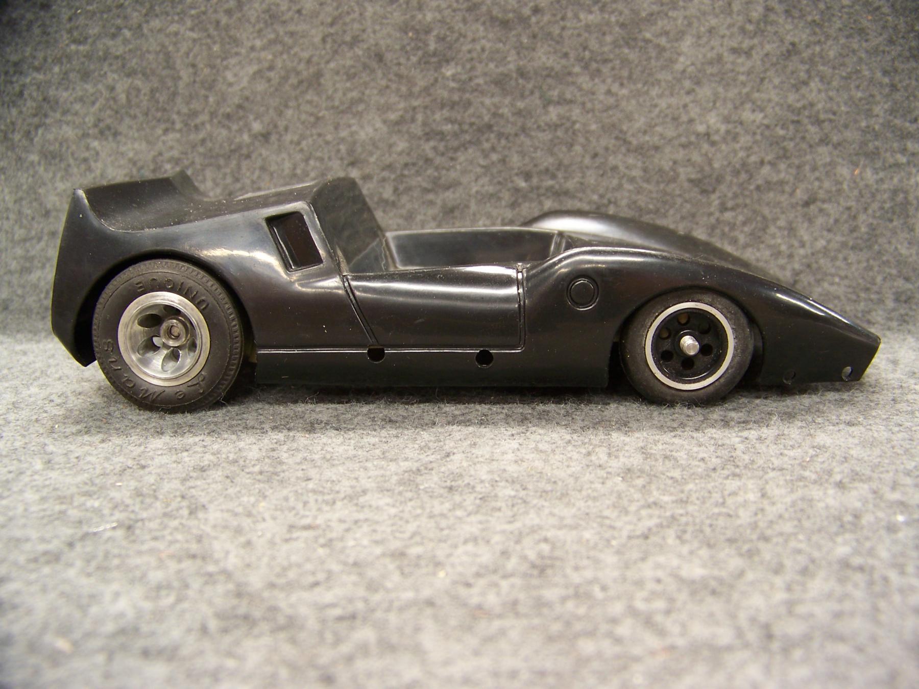
We have seen 3 cast metal chassis at the LASCM. I would think, and we have read, that there were a few prototype injection molded bodies around and of course the clear bodies that were sold in plenty back in the 60s?
 
That all changed after almost 60 years when a box of Bat bodies were found. They were auctioned 4 at a time for many weeks on eBay. Did you get any?
 
Hard to guess exactly how many were sold but I would guess some of you got some of them? 
I won a few and parked those believing one day I would make a chassis that was very close to the original. At least in looks and fit. Sure would be nice to have a chassis that fits the body with no modifications as MDC intended.
 
Every now and then, I see Bat bodies for sale on eBay with different mismatched production chassis, and makeshift windshield etc.
 
So the day arrived that I took a Bat body off my shelf and I made a scale drawing of what I was seeing from photos, and started to think how you would make this chassis today with the tools at my disposal. I studied all the pics I could find on the web and read all about how rare this body had been thought to be just a few years ago.
 
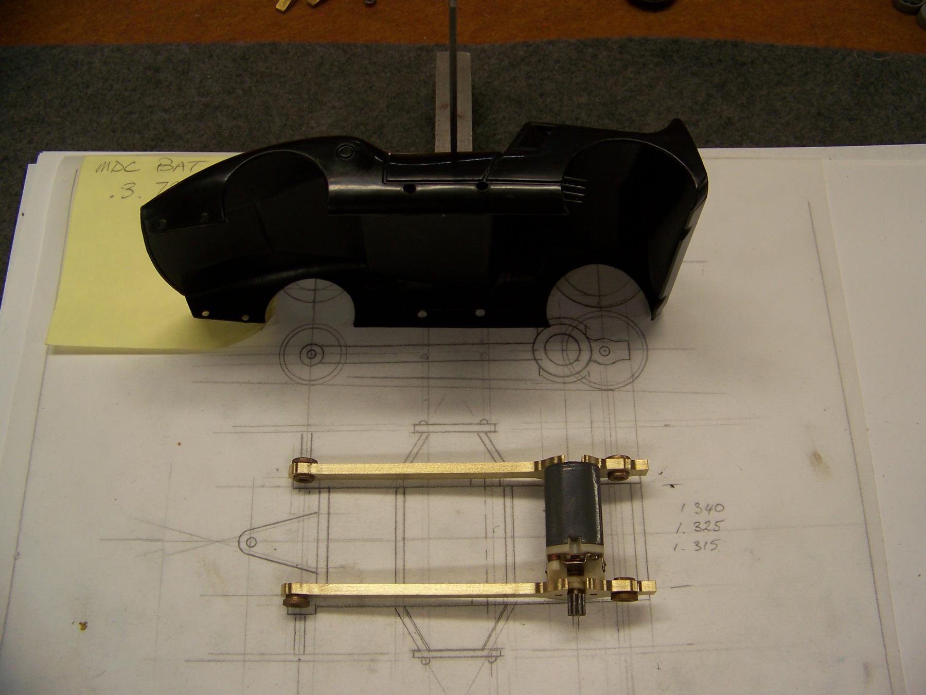
I made a brass sample of the main frame members that connected the rear axle motor and front axle, all on one straight line, kind of clever I thought and easy to do on my manual mill.
I mounted the motor, axles and mock-up wheels only to find out the chassis hit the molded interior tray and would not let the body sit anywhere close to fitting over the wheels. Glad I checked this at this stage, did MDC intend to cut out that interior part or ???
 
102_8459.JPG
 
Anyway, time for version 2. Seen below and the 1st version to compare.
 
102_8475.JPG
 
102_8474.JPG
 
Second version seen here with the lowered frame rails so the body will sit down on the chassis as intended.
Is this oversight what killed the project almost 60 years ago????
Wow! what a thing to find out after the dies and tooling had been made.
 
So how to make this chassis so other folks could have this RTR car to drive and have in their collection too and to continue where MDC had left off. 
 
CNC milled was considered. Too expensive with the number of operations and the fact that the chassis has a lot of tight corners and angles that would be hard to mill except with very small tools which would be slow to do.
 
Die casting, as the prototypes were done that way and would be the best option if it were not for the very expensive steel tooling that would be needed. The original tooling may be out there but still it does not fit the bodies that we have, so better think of a better solution.
 
Lost wax casting. Which I have a lot of experience with. Simple tooling but multiple steps, plus finishing, make this method too expensive also. 
 
Then I remembered working with Larry on some 3D printed parts not so long ago. I called Larry and he was interested enough to look at my drawings and sketches and convert and turn into a file that we could do a 3D test print. Sounds easy but Larry spent a lot of time on details with enthusiasm and without complaint to make this chassis as close to what MDC would have made IF they would have made a chassis that actually fit the body correctly. 
 
Of course MDC did not have computers or 3D printing to check fitment back then, but we do now, and we did. We made several test prints to make sure the body fit was correct and clearance over those big wheels was perfect. Making sure that gearing fitment was suitable also. As of this writing no track testing has been made, but we all know this type of design car was obsolete while it was being made at MDC in the 60's. So its place now is a collectable vintage car that for me will be fun to race with other hard bodied RTR cars of that period and style.
 
Probably not the only model that was just too late to the party. But it's a new day and a bit of revisionary slot car history. 
 The Bat is back and ready for a new build. :) 


  • don.siegel and Gene/ZR1 like this
Martin Windmill

#6 Dave Crevie

Dave Crevie

    Posting Leader

  • Full Member
  • PipPipPipPipPipPipPip
  • 4,422 posts
  • Joined: 16-February 09

Posted 08 November 2024 - 01:19 PM

That design concept was pretty popular for a while, but with much thinner sheet stock. I see the idea for using heavier brass, to bring up the weight, but the COG is much too high. I have a pair of brass side plates I made for a chassis probably c.1964. But only did one chassis that way. I switched to aluminum for side plates right away. And used padlock motors to power them. Cans hadn't become so popular around here yet. 


Kudos for bringing this chassis back to life. 


#7 don.siegel

don.siegel

    Grand Champion Poster

  • Subscriber
  • PipPipPipPipPipPipPipPip
  • 5,816 posts
  • Joined: 17-February 06
  • Gender:Male
  • Location:Paris, France

Posted 08 November 2024 - 01:23 PM

Great story Martin. And excellent work by you and Larry. 


Put me on the waiting list! 


Don 


  • ajd350 likes this

#8 Mark Mattei

Mark Mattei

    Mid-Pack Racer

  • Full Member
  • PipPipPip
  • 197 posts
  • Joined: 21-September 07
  • Gender:Male

Posted 09 November 2024 - 04:28 AM

Hi Martin, great research work on the Bat. Put me down for two chassis if they become available. Thank you, Mark Mattei.

#9 Martin

Martin

    Posting Leader

  • Full Member
  • PipPipPipPipPipPipPip
  • 4,180 posts
  • Joined: 22-February 09
  • Gender:Male
  • Location:US

Posted 09 November 2024 - 12:19 PM

Not sure if you guys want to know how we got here but I will share with you how Bat crazy we got.


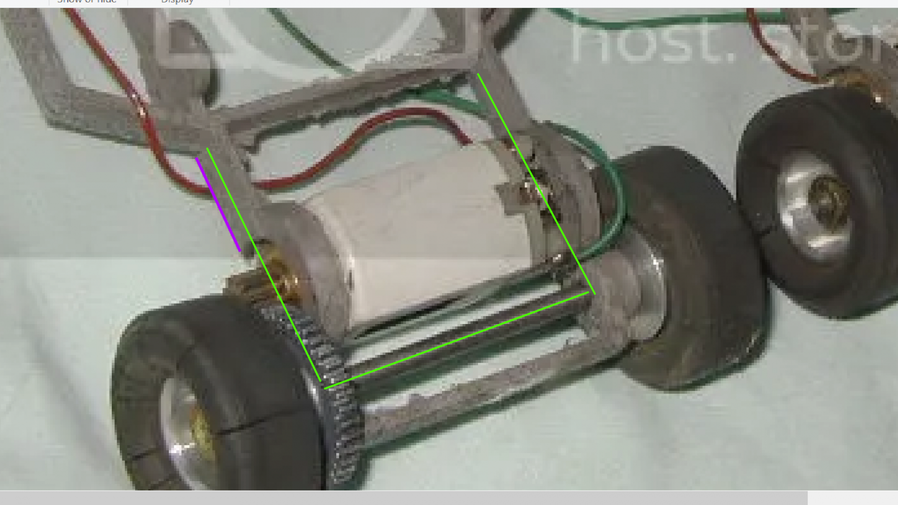
Once I had found and studied the photos (credit to LASCM) of the original test chassis it became apparent that the original cast chassis was indeed a straight line from axle to axle with the motor on that same line.

This is why I made my first brass prototype that way. This was the pic that sent me in that direction. But as I found out that design would work with the clear body but not the injection body. Which I think we all have?


motor mount 1.png


  • don.siegel likes this
Martin Windmill

#10 Dave Crevie

Dave Crevie

    Posting Leader

  • Full Member
  • PipPipPipPipPipPipPip
  • 4,422 posts
  • Joined: 16-February 09

Posted 09 November 2024 - 12:59 PM

Ok. I definitely want to make sure I know where you are going with this. Do you want to make an exact copy of the BAT chassis? Are you planning on having it 3D printed? Have you made a complete, dimensioned drawing of the original chassis. (preferrably a 3D model)  I think this is a great project, and you certainly have done some research. Wish I had done more of it while I was working and had access to everything I needed to make new die cast versions. 


#11 Martin

Martin

    Posting Leader

  • Full Member
  • PipPipPipPipPipPipPip
  • 4,180 posts
  • Joined: 22-February 09
  • Gender:Male
  • Location:US

Posted 09 November 2024 - 02:14 PM

"Are you planning on having it 3D printed? " Yes.


"Do you want to make an exact copy of the BAT chassis?" yes but we fixed the MDC prototype chassis problems.


The MDC chassis porotypes problems are listed below.....


1/ Chassis interferes with interior tray. Now fixed with new design.


2/ Chassis pins do not position body in correct location.  Now fixed with new design.


3/ New chassis now has positive hold down clamp to secure motor.


4/ Rear axle rides on MJF material or has recess for bushings or ball bearings.


5/ MDC guide hole ( which was too high to reach the track) now repurposed as an adjustable up stop for the wire drop arm.   


6/ Two versions of the chassis one for Big bearing 16D and one for the Small bearing 16D can motors. 


I will add details as needed or as I think of them. Thanks for you interest and questions. 


Martin Windmill

#12 don.siegel

don.siegel

    Grand Champion Poster

  • Subscriber
  • PipPipPipPipPipPipPipPip
  • 5,816 posts
  • Joined: 17-February 06
  • Gender:Male
  • Location:Paris, France

Posted 09 November 2024 - 05:50 PM

Now, that's a very impressive project! 


Good thinking guys. 


Don 


#13 Dave Crevie

Dave Crevie

    Posting Leader

  • Full Member
  • PipPipPipPipPipPipPip
  • 4,422 posts
  • Joined: 16-February 09

Posted 10 November 2024 - 08:57 AM

If you want to do hard body, then resin is the way to go in such small volumes. I've cast lots of bodies, and using my system they are as thin as model kit bodies. The resin I use is high impact, so they take a lot of bangin' around.


#14 Martin

Martin

    Posting Leader

  • Full Member
  • PipPipPipPipPipPipPip
  • 4,180 posts
  • Joined: 22-February 09
  • Gender:Male
  • Location:US

Posted 10 November 2024 - 10:57 AM

Dave I would like to talk to you more later about making my own design Thingy.


Back to making a complete MDC Bat car. 


I want to take stock here. Many of us have the Bat bodies which is why I took on this project.


The main missing items are the chassis, canopy, and bumper. All of which are in process.


Here is part of that process. 


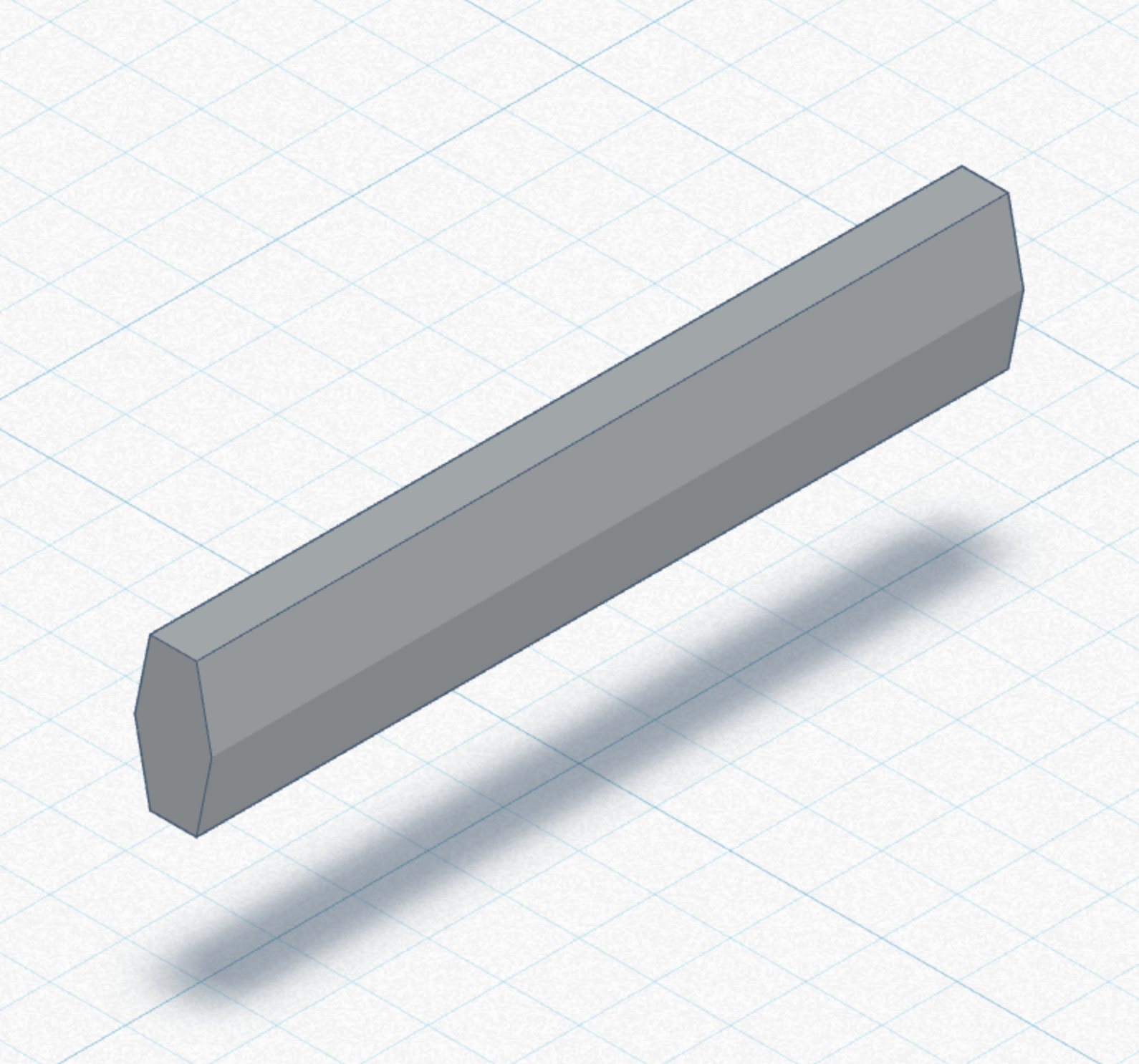
We started with the main construction beam, its looked like a elongated hex in the pics. My brass prototype was 1/8" by 1/4" so we went with that.


Screenshot 2024-05-29 at 4.18.28 PM.png


Larry and I spent a lot of back and forth with sketches and thoughts to try and capture what we were seeing.


This is an example of how we arrived at a finished chassis. Larry would then turn this into 3D CAD. Lots of back and forth.


Screenshot (2463) small.png


  • don.siegel likes this
Martin Windmill

#15 Martin

Martin

    Posting Leader

  • Full Member
  • PipPipPipPipPipPipPip
  • 4,180 posts
  • Joined: 22-February 09
  • Gender:Male
  • Location:US

Posted 10 November 2024 - 12:39 PM

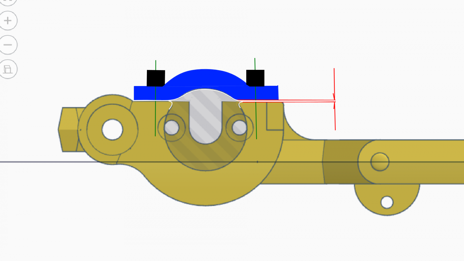
Another detail that we felt was totally missed on the original MDC chassis was the way the motor was held in place. 

The end bell was screwed in but the fact that the original was Can drive meant the motor had a chance of moving. So this is how we fixed that issue.


mod motor clamp.png


Ortho.png


Martin Windmill

#16 Dave Crevie

Dave Crevie

    Posting Leader

  • Full Member
  • PipPipPipPipPipPipPip
  • 4,422 posts
  • Joined: 16-February 09

Posted 10 November 2024 - 01:38 PM

Dave I would like to talk to you more later about making my own design Thingy.


As Jerry Kulich would say, "I'm here for you".


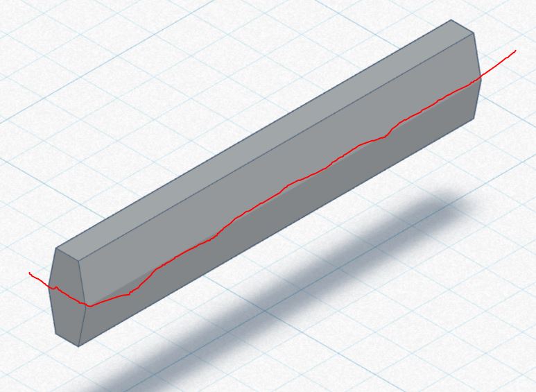
The shape of the main rail, and all other horizontal surfaces, contains draft for the die casting process. The part tapers down from the width at the parting line, to the width at the depth of the cavity. The parting line follows the red line in the drawing below.


aaabatrl.JPG


Without draft, it is difficult to get the part out of the die. If you are going to 3D print these, you don't need draft. The sides can be dead flat.


#17 Martin

Martin

    Posting Leader

  • Full Member
  • PipPipPipPipPipPipPip
  • 4,180 posts
  • Joined: 22-February 09
  • Gender:Male
  • Location:US

Posted 10 November 2024 - 02:40 PM

Thanks for that Dave, 3D printing has a lot of advantages as we know the main one in this case is no tooling needed, the draft shape is now just there to replicate the look of the original.

I guess you might say the CAD file now replaces the physical tool.

I was a mold and pattern maker for a living in a past life so I do know about draft etc.  :) Thanks for your input.


Martin Windmill

#18 Martin

Martin

    Posting Leader

  • Full Member
  • PipPipPipPipPipPipPip
  • 4,180 posts
  • Joined: 22-February 09
  • Gender:Male
  • Location:US

Posted 11 November 2024 - 10:17 AM

We designed 2 versions of this chassis, one for what we call the Small Bearing (SB)16D motor and one for what we call the Big Bearing (BB)16D motor.

The original MDC prototypes where all BB can drive but the one advantage of the SB is the fact that the motor is symmetrical as is the chassis, so you can drive from either side with a CW or CCW direction motor. 

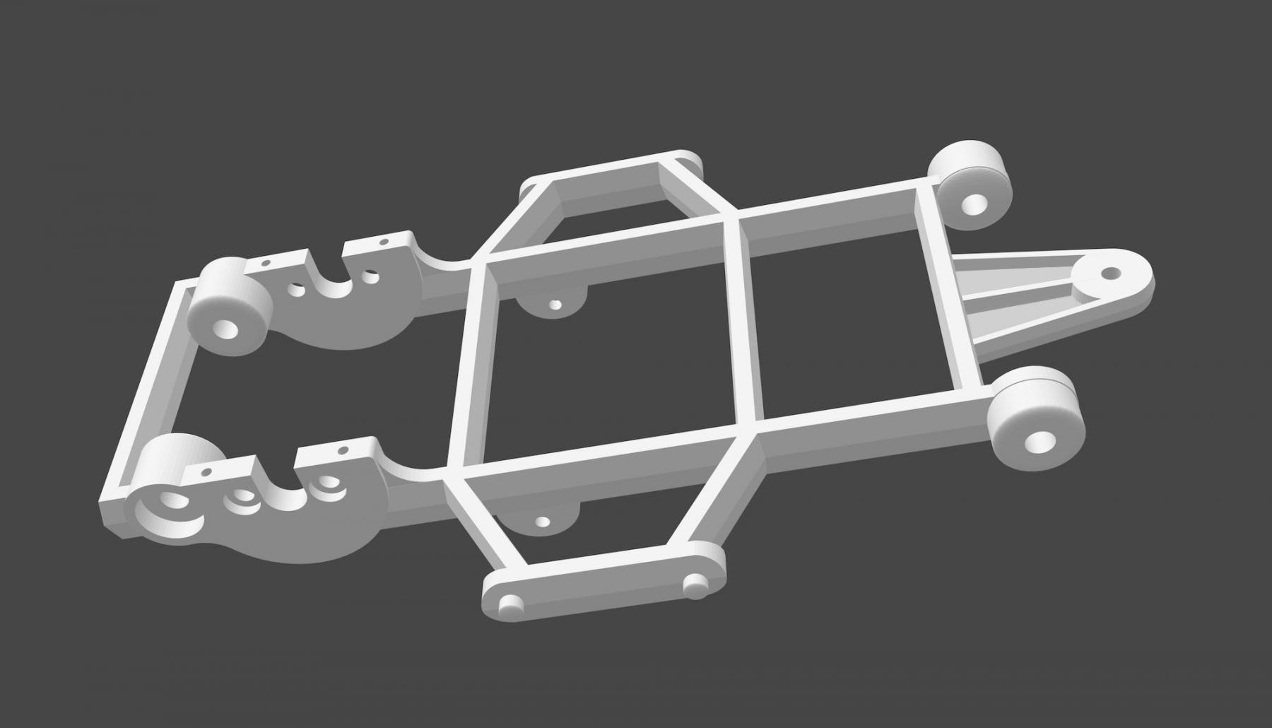
Here is a pic of the SB chassis ready to print a sample. We wanted to check a few things. 


1/ As the motor to axle are fixed gearing backlash needs to be checked.


2/Holes for axle and bearing or bushing also needs to be checked,


3/ Wheelbase and track all need to be verified.


4/ Make sure the mainframe rails fit comfortably with the interior tray.


5/ One of the hardest things' to get correct is how the body fits to the chassis. If this is off just a small amount the tires could rub and or the wheels may not be centered in the wheel arch.  

These last 2 items were where we think MDC messed up. We have the advantage of being able to 3D print a sample, lets see if we can get a perfect fit, or at least know what to change?


Money shot.jpg


Martin Windmill

#19 don.siegel

don.siegel

    Grand Champion Poster

  • Subscriber
  • PipPipPipPipPipPipPipPip
  • 5,816 posts
  • Joined: 17-February 06
  • Gender:Male
  • Location:Paris, France

Posted 11 November 2024 - 10:35 AM

That looks very good, Martin, but something will probably be a little bit off on the first run... 

What size tires/wheels is this designed for? How about approximate gear ratio? 

I assume you're sticking with the motor on its side mounting, so it would be a 16D, probably the same white Panther as in the other kits... with the big bearing - but I like your thinking on the FT16 (Russkit 23 or Cobra would keep the blind bearing, but provide heat sinks and a hotter winding).  


Don 


#20 Martin

Martin

    Posting Leader

  • Full Member
  • PipPipPipPipPipPipPip
  • 4,180 posts
  • Joined: 22-February 09
  • Gender:Male
  • Location:US

Posted 11 November 2024 - 10:57 AM

The wheel size is basically controlled by what looks good in the wheel arch of the original MDC Bat body.


1 -1/16'' o.d. rear(27mm) and 7/8" or 22mm front looks about right. Anything smaller and the tires get lost in those rather large wheel arches.

I will also try 1-1/8"rears and 15/16" o.d. front tires shown in pic below, and have the option of 10/43 gearing. TBD.


As the 27mm rear tire diameter is the same as the Russkit Carrera cars (16d sidewinder) I figured to use the same gearing they used which is 10/41. All this could be change as we have the ability to print our own gears but I feel this is is a good place to start.


102_8465.JPG  


Screenshot mdc wheels.png


  • don.siegel likes this
Martin Windmill

#21 Riccardo

Riccardo

    Backmarker

  • Full Member
  • PipPip
  • 78 posts
  • Joined: 19-October 11
  • Gender:Male
  • Location:Venice, Italy

Posted 13 November 2024 - 09:22 AM

 Martin ! An useful project and  excellent job !


Put me on the waiting list if it becomes available.


Rick


Riccardo Chiriatti

#22 Martin

Martin

    Posting Leader

  • Full Member
  • PipPipPipPipPipPipPip
  • 4,180 posts
  • Joined: 22-February 09
  • Gender:Male
  • Location:US

Posted 13 November 2024 - 10:32 AM

Thanks Rick and others that are encouraging this build.

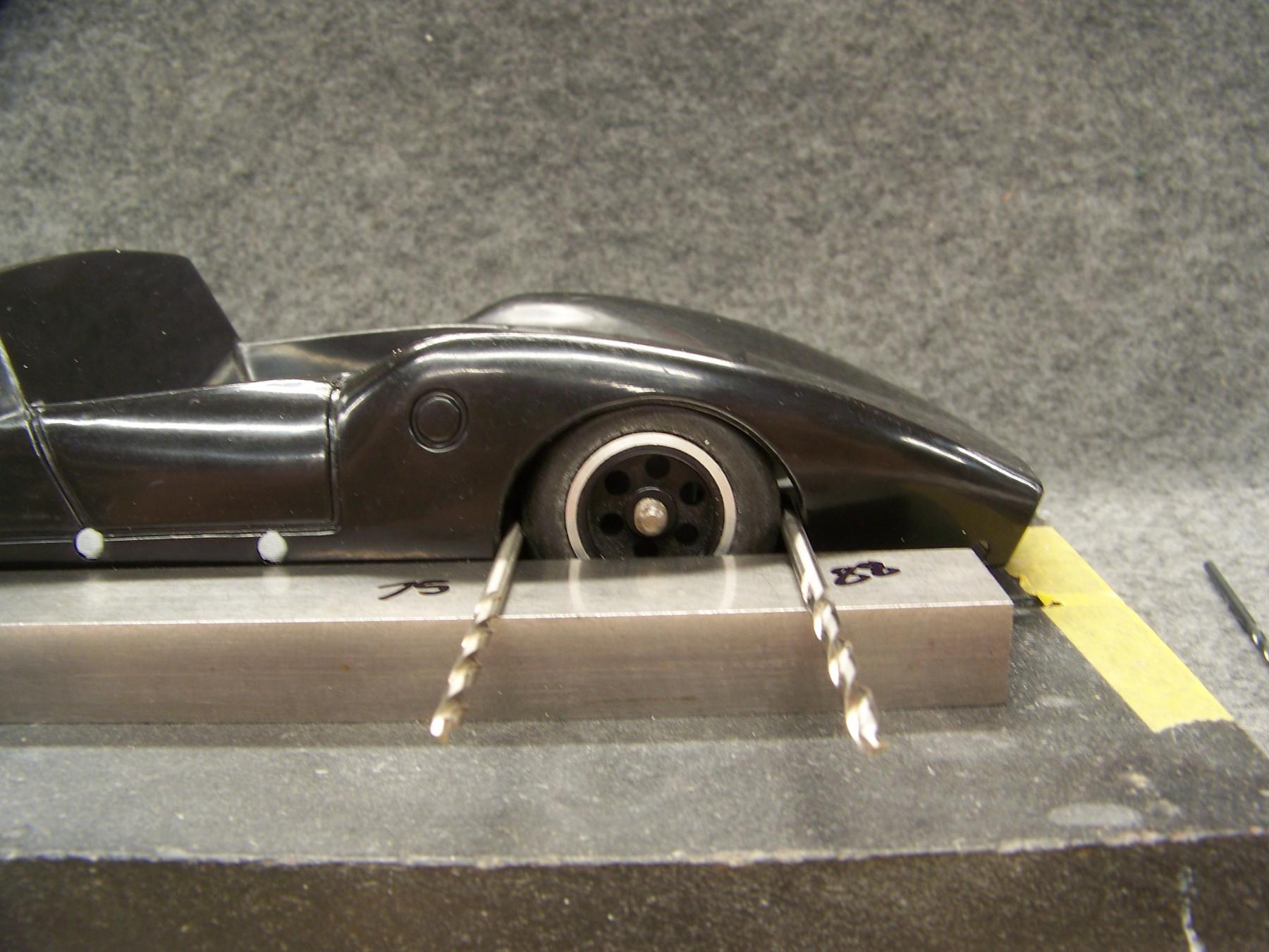
After several samples to get the stance of the body sitting perfect on the chassis we were finally satisfied. As you can imagine the holes in the body are a given by MDC so our body pins are super critical. 1 degree or .010" either way and the wheels would not be in the middle of the wheel arch or worse, would rub on the tires. With careful measurements and lots of dedication ( thank you again Larry) we got there.  

We took advantage of 3D printing a technology that had not even been thought of when MDC made their tooling.

Here are a couple of pics of some of the ways we dialed it in.  That saying, 3rd time's a charm works for some reason?


102_8512.JPG


102_8506.JPG


102_8544.JPG


  • don.siegel likes this
Martin Windmill

#23 Dave Crevie

Dave Crevie

    Posting Leader

  • Full Member
  • PipPipPipPipPipPipPip
  • 4,422 posts
  • Joined: 16-February 09

Posted 13 November 2024 - 01:42 PM

Don't get too paranoid about the wheel arches. Some changes can be made to the mold if you are going resin, with RTV molds. Even then, the materials are cheap enough, (compared to a hard metal mold) that more drastic changes can be made in the 3D model, and a new mold half made. Keep in mind that the 3D model has to be 6% oversize to allow for shrinkage in the resin. 


#24 Martin

Martin

    Posting Leader

  • Full Member
  • PipPipPipPipPipPipPip
  • 4,180 posts
  • Joined: 22-February 09
  • Gender:Male
  • Location:US

Posted 13 November 2024 - 09:53 PM

Always good to have your input Dave. 

But just to recap our objectives in this particular project. 


We know there were hundreds (maybe ?) of MDC Bat bodies injection molded in red and black, they were discovered and sold on ebay 4 at a time a couple of years ago.

What we have done here is to make an original looking chassis to fit those existing MDC Bat bodies.

Fixing the chassis shortcomings along the way.

So no need for anymore bodies, just want to use the original ones I (we) already have.


Part of the reason this chassis was a bit tricky was the body mounting holes had already been put into the body by MDC, not to mention the prototype MDC chassis looks to me like it would interfere with the interior tray also and so would not let the body sit down onto the wheels.

All fixed now. :victory: Found that out on the first brass chassis I made.


The latest part, is this really nice canopy from a very skilled slotblog member.  I am so glad he is on the Bat team and happy to say a good friend. The best part of this project is making friends that share the enthusiasm. 

They are .030" PTEG fit and look great.  To me the body only looks good with the canopy,  check it out. :)


102_8842.JPG


  • don.siegel likes this
Martin Windmill

#25 Martin

Martin

    Posting Leader

  • Full Member
  • PipPipPipPipPipPipPip
  • 4,180 posts
  • Joined: 22-February 09
  • Gender:Male
  • Location:US

Posted 14 November 2024 - 12:02 PM

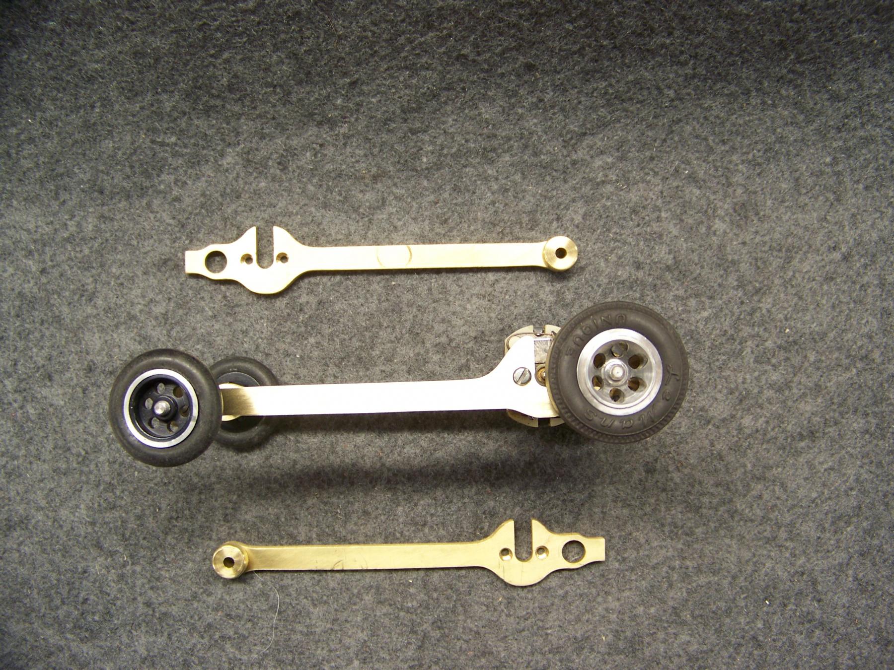
I have made 3 different designs of drop arms. The one in the pic on post 24 above. Is made with a Dynamic brass guide holder. 


These next two (below) are what I call the "Original" on the right of the pic and the fancyer one on the left I call "Reverse loop", unless anyone can think of a better name?


Both these two designs have the wire soldered into a groove in a turned brass guide pivot.

Love to hear which you prefer or which one you think I should go with?


droparm 60 per.png


Martin Windmill


Electric Dreams Online Shop