Jump to content


Photo

R-Geo R&D chassis build


  • Please log in to reply
15 replies to this topic

#1 One_Track_Mind

One_Track_Mind

    Posting Leader

  • Subscriber
  • PipPipPipPipPipPipPip
  • 2,966 posts
  • Joined: 16-February 06
  • Gender:Male
  • Location:Cleveland, OH

Posted 15 July 2011 - 07:48 PM

Received the new R-GEO summertime R&D chassis in the mail today.
Mr.RGEO asked for me to take pictures and shed my results, so figured I would hold to my end of the bargain
For some of US this maybe dull and mundane, but hoping some new builders may pick up on some things here as well. Please bear with me!

Posted Image

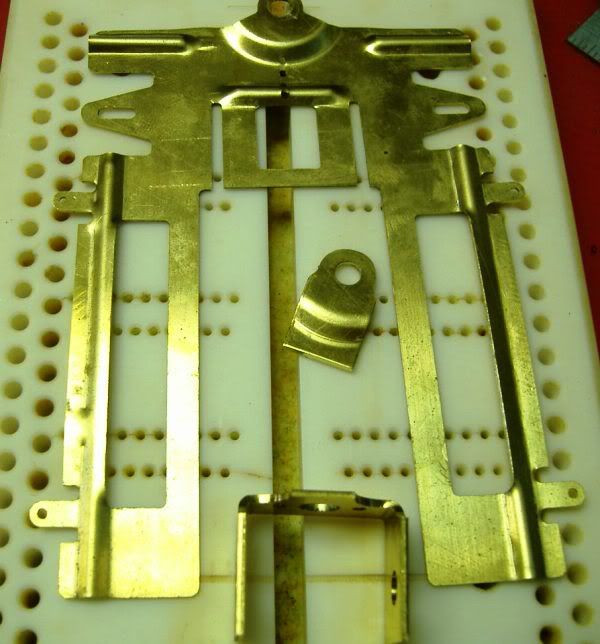
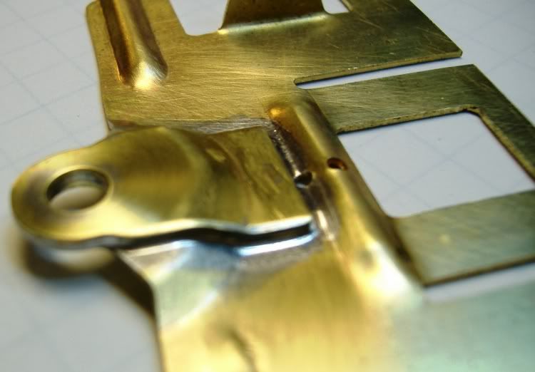
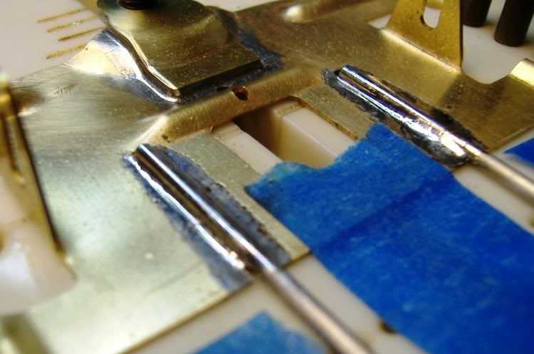
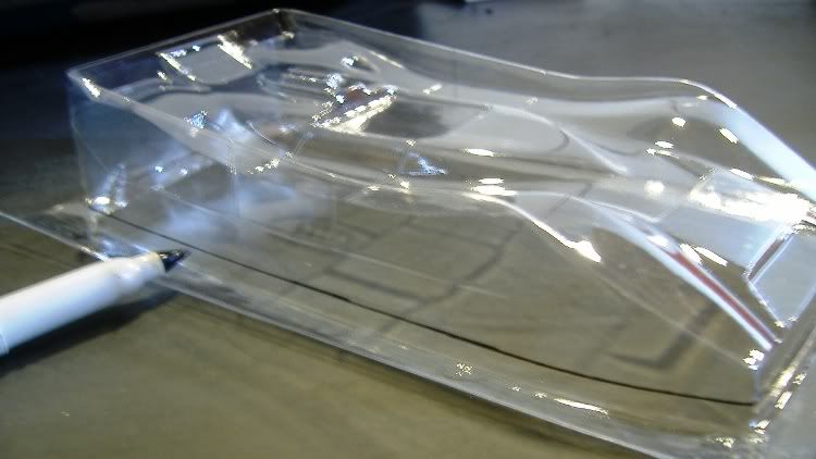
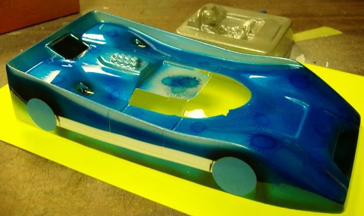
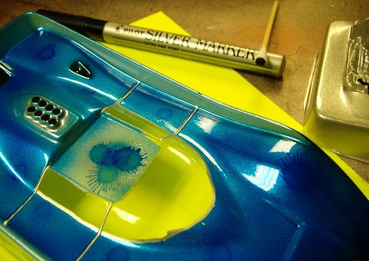
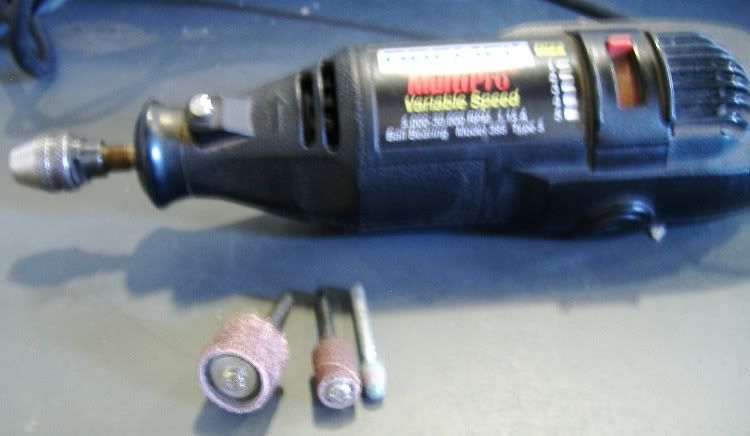
First thing I do is separate the pans by making a pencil line for my cut mark, I cut all my pieces by hand with a dremel tool and a abrasive cut-off wheel. Don't forget the eye protection!

Posted Image

Why do you ask that I cut it there? Well, for me it's easier to cut straight and file straight then doing the cut line at an angle and them making the pans look like they come off the front piece. It's a matter of choice to the builder.

Posted Image

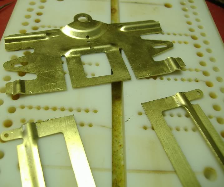
Notice: the burr left from cutting? This is where the good hand file comes into play, take your time and remember a file only cuts in one direction forward or away from you,it doesn't do any good to drag the file back and forth, but I do! It helps me to stay square and feel when the file is cutting.

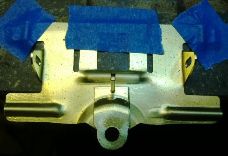
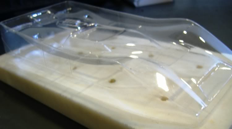
Very Important! make sure all your brass pieces are totally flat! Lay them on the jig block or glass or anything that you know is perfectly flat. tweak it here and tweak it there, be very concious about making them pieces FLAT!

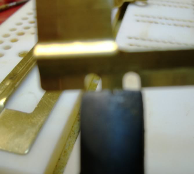
When bending the body mounts tabs I pick on my favorite pair of Channellock linesman's pliers.I know from bending many of these where and how far you should place the pliers to make the tab end up square.
Use your eye-crometer and look to make it stand straight up and down. bend more or less as neccesary.

Posted Image

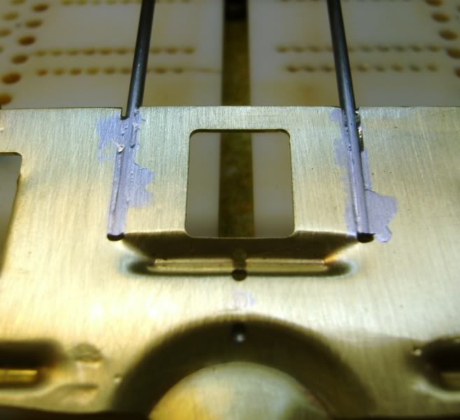
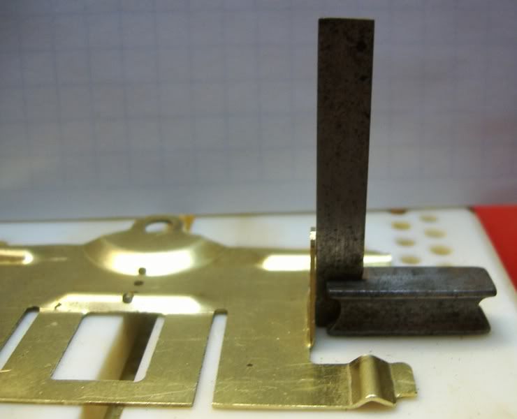
When bending the front uprights I do the same thing using the same pliers,this time though I make sure using this little machinist square there perfectly up right,this also tends to bend the front plate around again so make sure it still stays nice and flat.

Posted Image

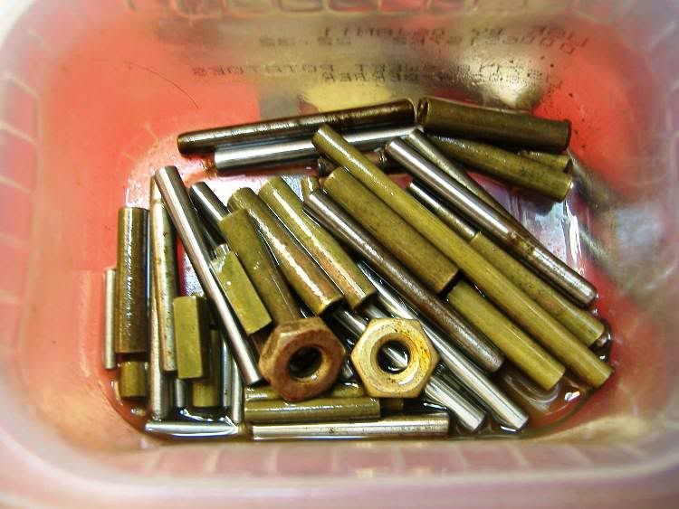
This is a trick, or a tip I should say I learned from watching the Mike Stuebe Scratch building DVD produced by our good friend Keith Tanaka.
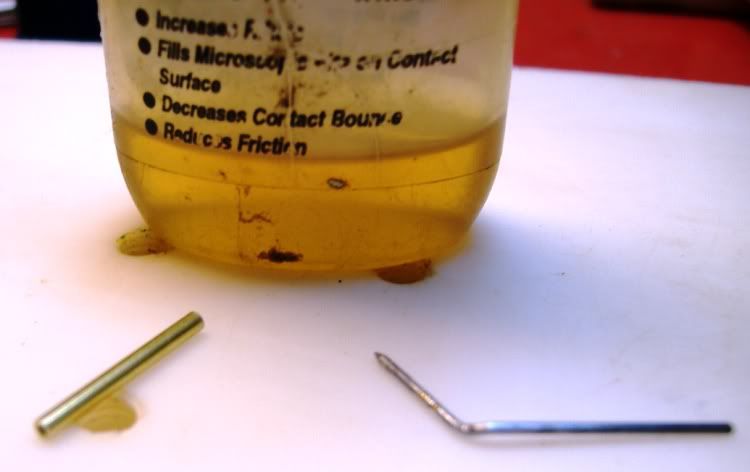
Get a small plastic container and keep all your jig pins in there,spray a little wd-40 in the bottom and shake them around. This particular container is a baby food tub from Gerber.
Yea, they get a little rusty here in Ohio, plus from all the acid during the soldering.

Posted Image

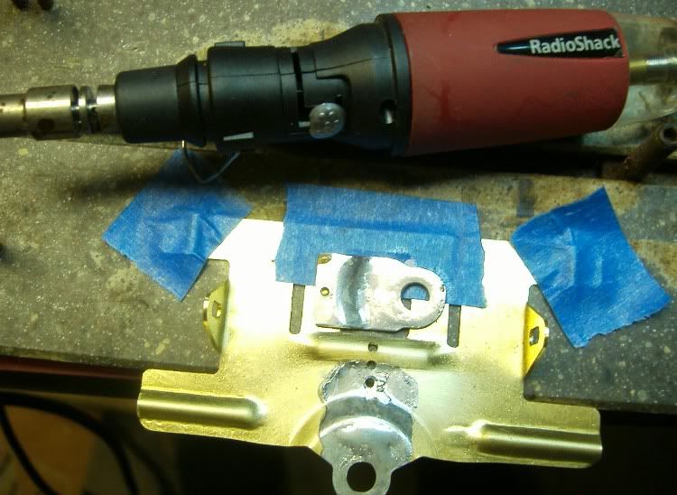
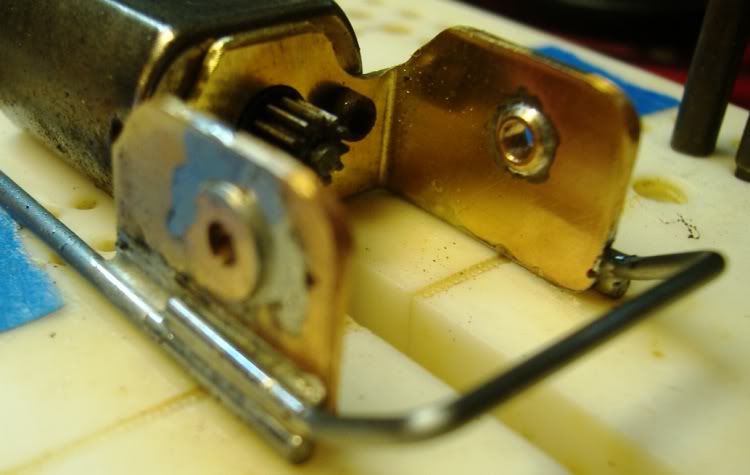
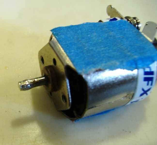
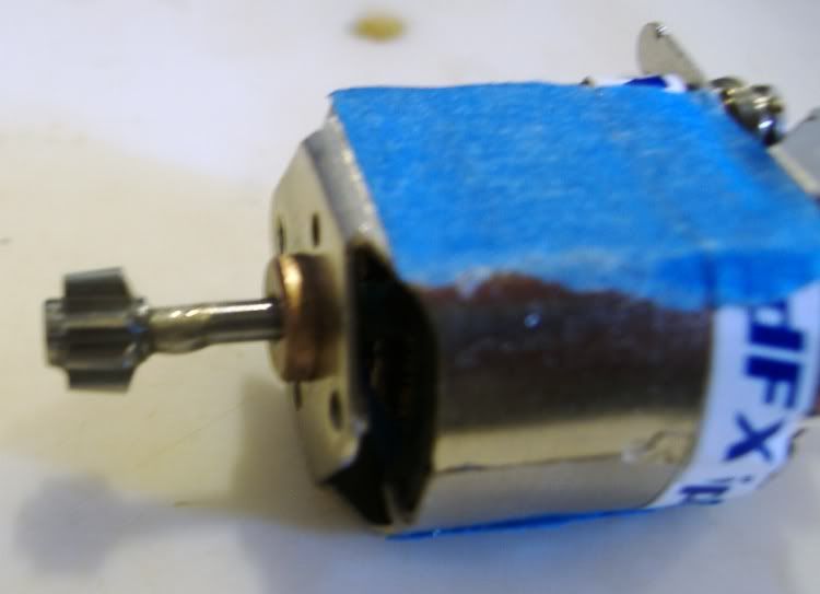
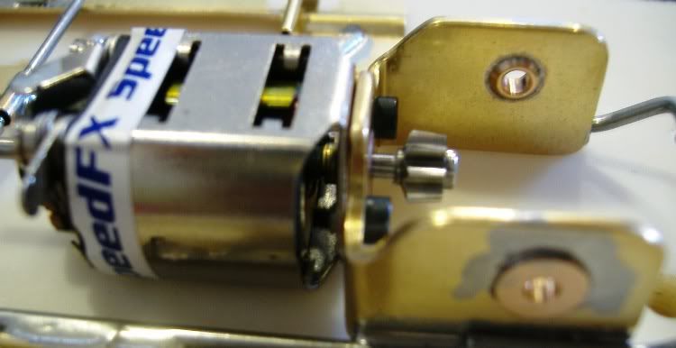
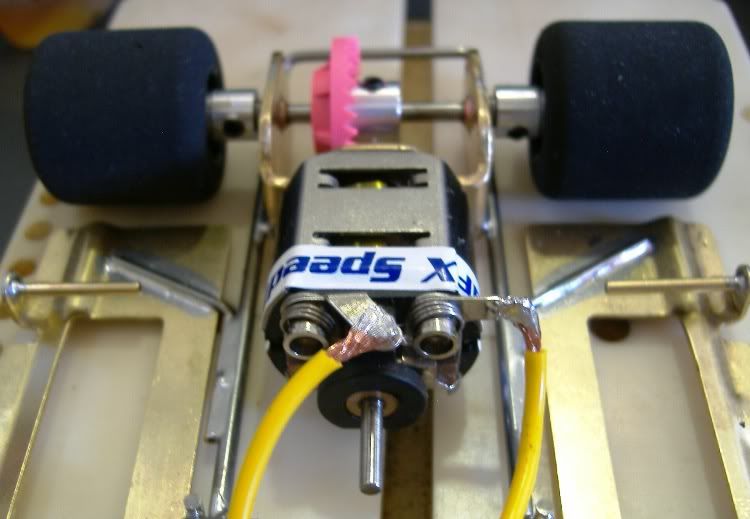
ok, so I missed a picture here of the modifications or plain hand filing of the motor bracket, again It's just me but I like all rounded corners with no sharp edges or anything on the motor bracket.Use the little machinst square and make sure it's nice and even and square all around the edges or uprights.

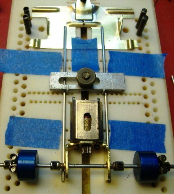
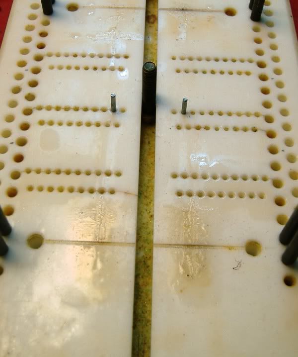
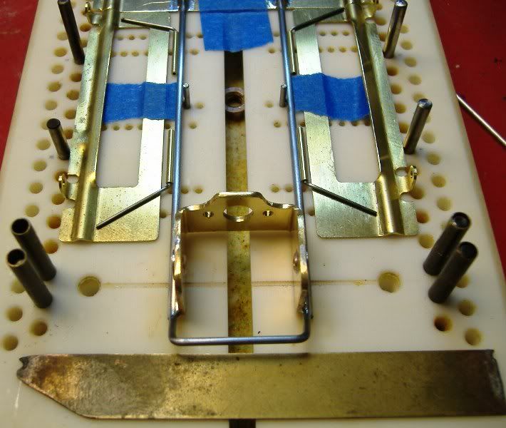
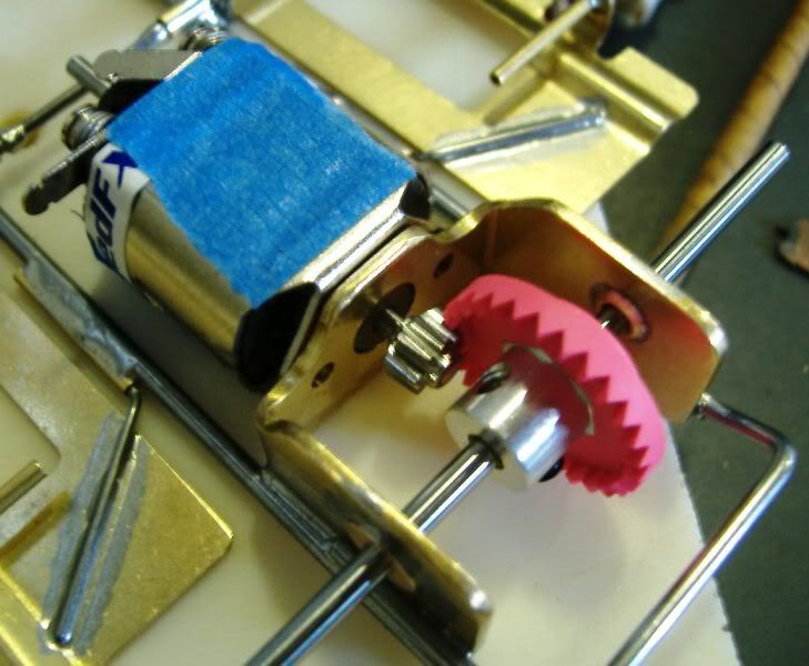
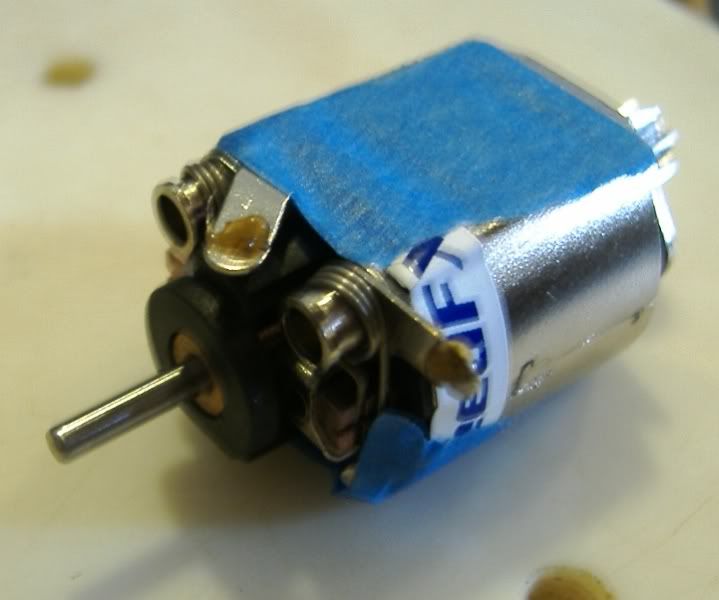
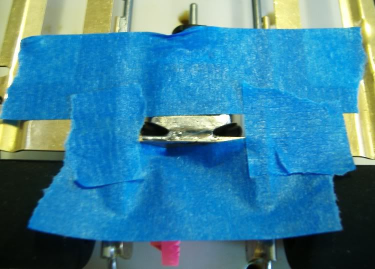
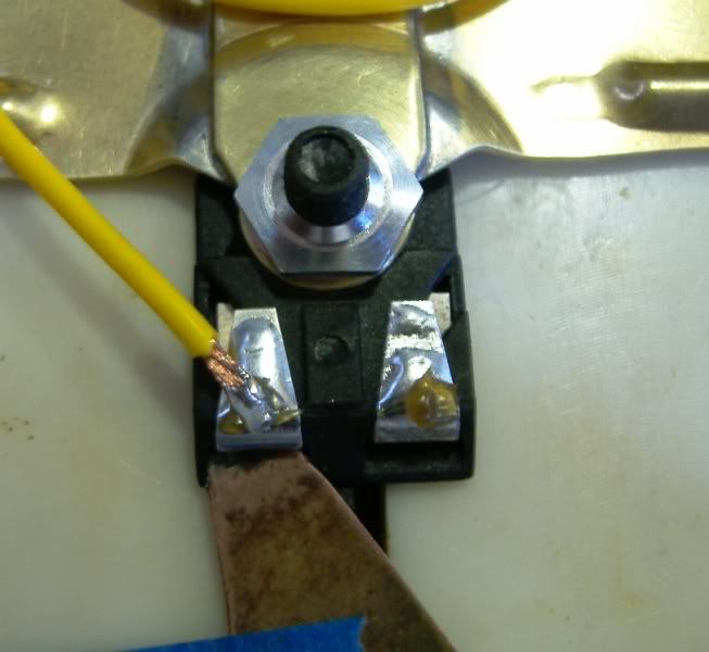
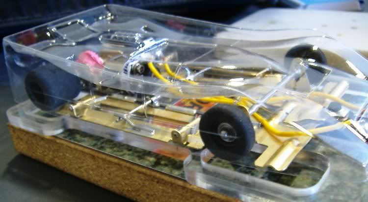
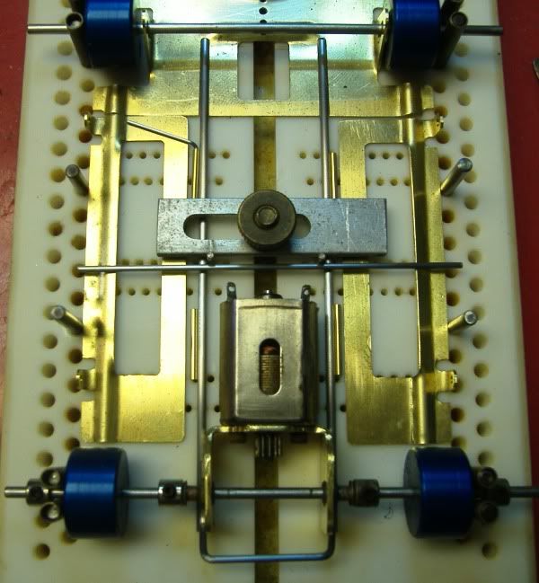
Here's I do the motor box set-up on my Rick's jig. Those blue anodized set-up wheels are another fine Product from RGEO.

Posted Image

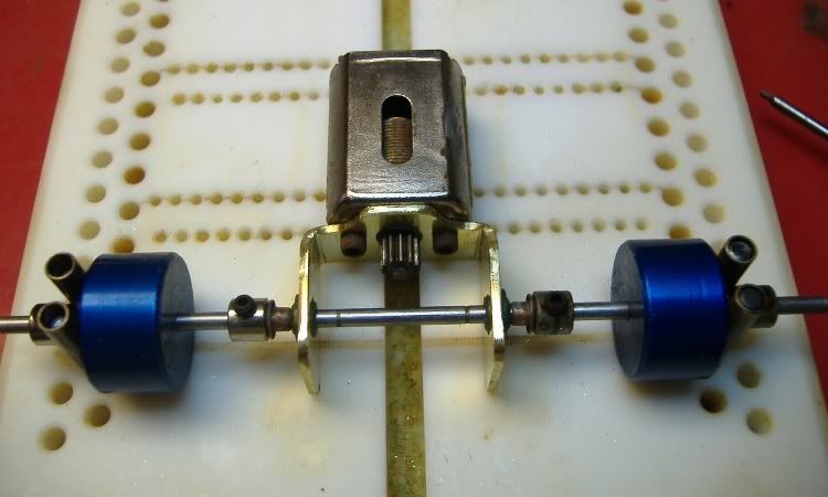
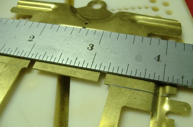
Now is when you need to decide the wheelbase for your car and set the jig wheels accordingly.This build will be a 4" wheelbase, pretty standard for my retro builds.
The main rails will be .078 since the front nose piece cut-outs were made to that size, but again all my can-am's run a .078 and the F-1's run a .062 main rail.
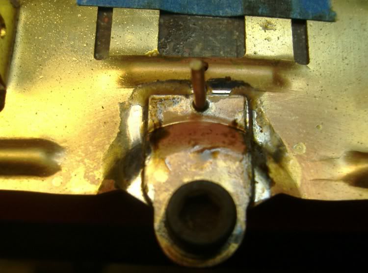
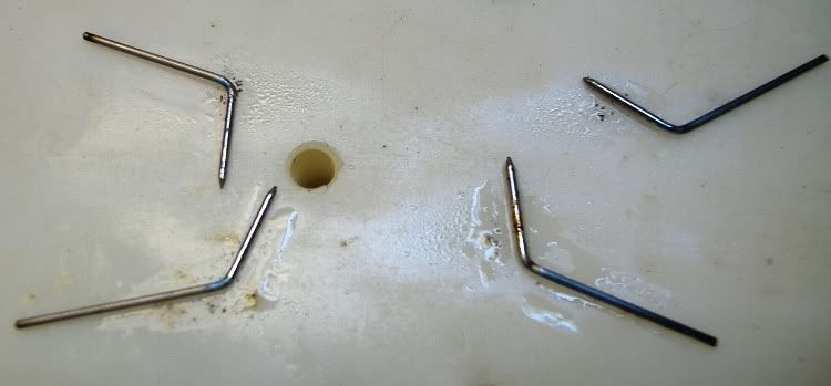
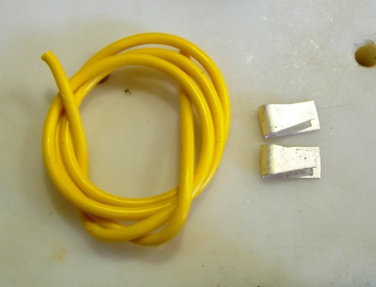
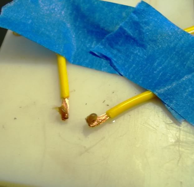
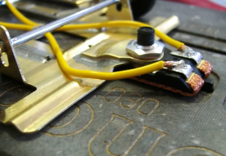
The hinge wires for the pans will be .032 wire and 1/16th pre-cut pin tubes from CLR

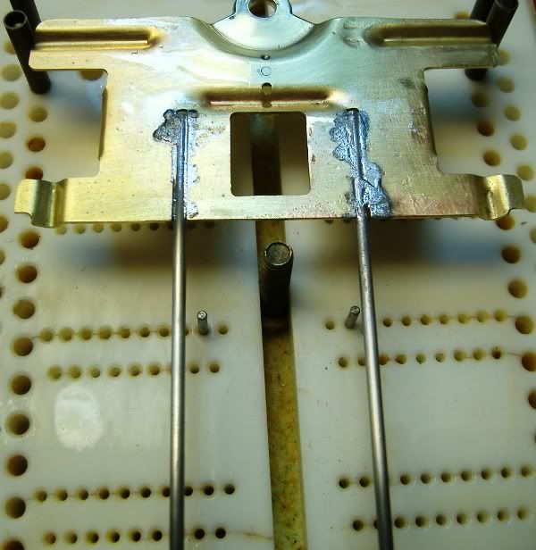
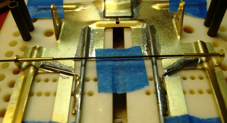
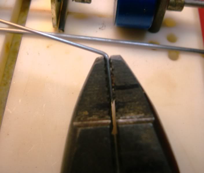
Same ole pliers are called for again, I have marks on there to make sure I place the wire into the pliers to the same depth for each one, before doing this though I grind a tip or sharp point on the end of the wire,and then make the bend,Then I hold real close the that bend and make a kink in the wire or a little step per say,this allows the wire to lye flat on the pan and be inside the pintube. Take your time and make sure this is right!

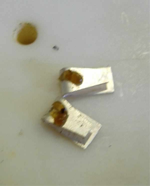
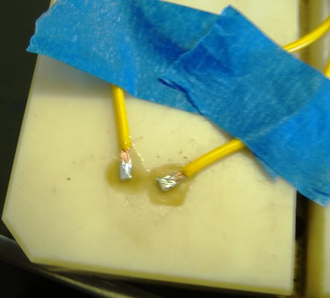
soldering pan hinge wires before always Helps or is easier to do before any bends are made,but I have found out from the jaws of the pliers will sometimes knick the solder and binds the wire up inside the pintube,maybe I'm doing something wrong,but I do the bends then solder them. This only keeps them from rusting inside the pintube.

Posted Image


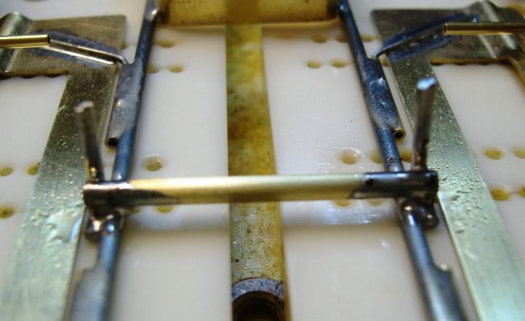
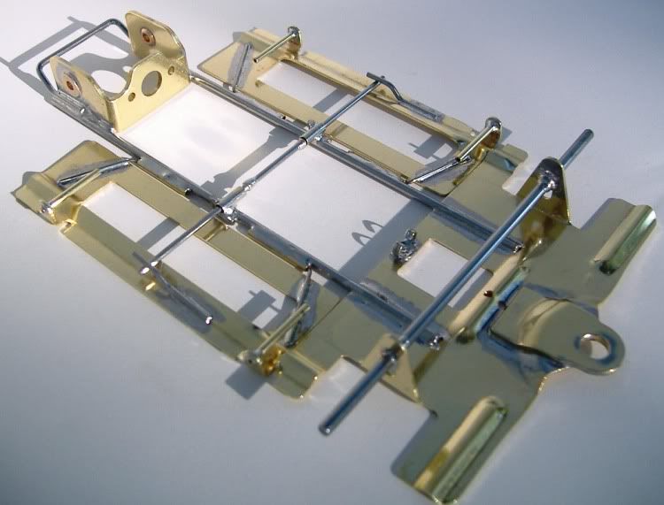
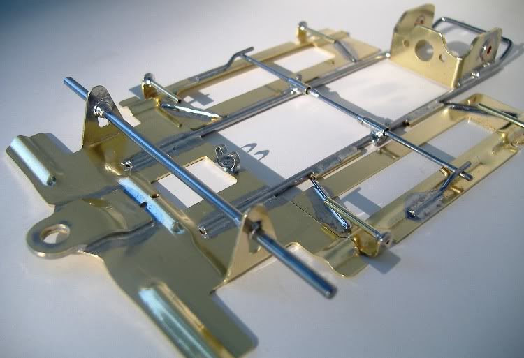
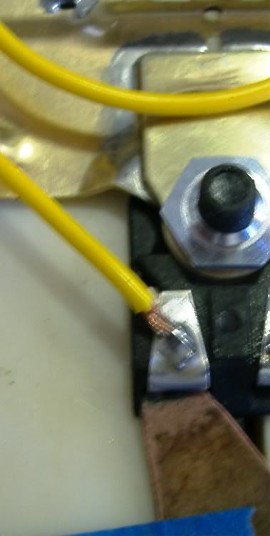
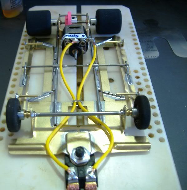
Personal preference for me is simply set-up everything on the jig before any soldering is done,It also helps during the siffer' mode so to speak. sometimes I will change from my original idea once everything is laid out on the jig. Why? because it just doesn't look right to me!
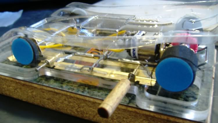
This build may end up with a .055 bite bar?
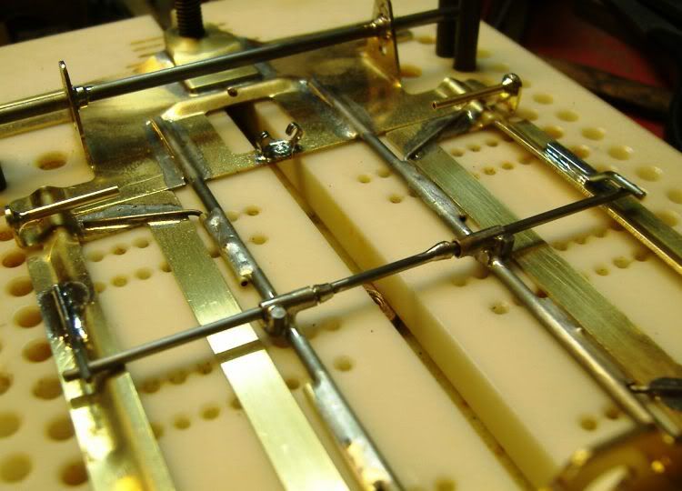
got three more wires to bend for the pans,and I forgot to mention that the front nose piece stiffener,That will be the first thing we solder in the next segment of the build. I'll show you how I do it,I'm sure there's plenty of better ways,but this works for me with good results.

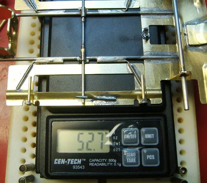
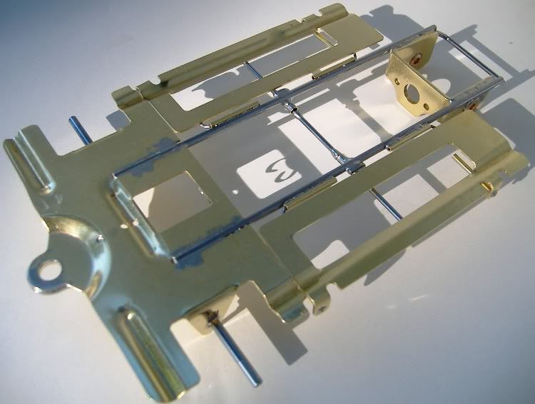
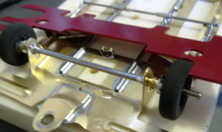
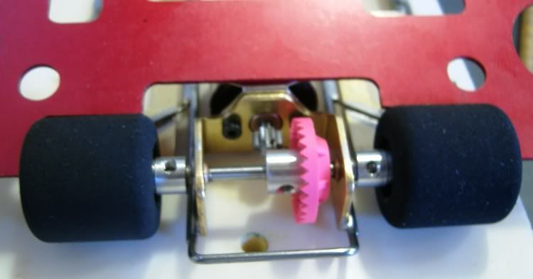
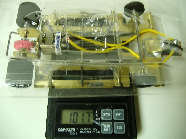
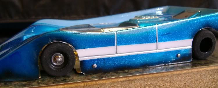
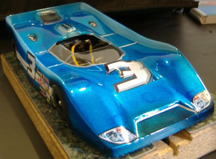
Here's the complete progress thus far,

Posted Image

Oh,Yea, forgot to mention my patended wonky gear guard made from .062 wire. :shok:

Slots-4-Ever
Brian McPherson

REM Raceway

"We didn't realize we were making memories, we just knew we were having FUN!"


#2 One_Track_Mind

One_Track_Mind

    Posting Leader

  • Subscriber
  • PipPipPipPipPipPipPip
  • 2,966 posts
  • Joined: 16-February 06
  • Gender:Male
  • Location:Cleveland, OH

Posted 16 July 2011 - 07:44 PM

When we last left off on the build I talked about some modifications to the front guide stiffner,well other then drilling a hole for a solid piece of 1/16' brass rod and making sure all the edges were filed nice and smooth,it was time to tape it down to an old jig block.

Posted Image

I first tinned both pieces and got out the heat! a Radio Shack min-torch.

Posted Image

Before placing the brace on top again more flux is added to both pieces,to make sure the holes line up place a bolt and nut thru the flag hole. Don't overtighten the nut as this will cause the piece to raise up in the back,just lightly snug it.
Fire up the torch and applying heat all around and underneath. you'll see the acid starting to bubble and then the solder will flow and the piece settles down nice and flat. At this point let it cool!, don't touch!

Posted Image

Once it nice and cool cut off the excess brass rod and file smooth,then take some red scrotchbrite and clean it all up.

Posted Image

Soldering the main rails to the front nose piece and to the motor bracket this is my set-up.The hold down is just barely snug to just hold the main rails secure. Don't overtighten this and tweak the rails. you want them to lay nice and flat in a natural state.
The tape is placed on the jig just to keep the acid from going in those holes.

Posted Image

When soldering the main rails this takes quite a bit of heat as the brass really takes the heat quick away from where your soldering. Again, I like to put more solder here then what is probably needed,like a little fillet.

Posted Image

And when putting too much solder from the top is comes thru to the bottom,but nothing a file and some scotchbrite won't fix.

Posted Image

The motor bracket and rear brace in place .Again take your time here with the heat as these thick brackets will take it away,especially when a motor is bolted to them.

Posted Image

So now at this point the front and rtear of the chassis are connected,Go to the washsink and take along an old toothbrush and scrub the acid clean of everything.I then blow it dry with compressed air.

Oh, yea here is that bottom solder joint,prettied up a little.

Posted Image

This is one of my favorite companions when building,to keep everything nice and clean,i use this on most everything on a slot car and the jig,to clean up acid.

Posted Image

The left-over acid that is cleaned with the rag soaked in alcohol. Personal preference here I reckon to how clean you want to keep your block during the build. Since the soldered pieces were already scrubbed in the sink this only makes since to me.

Posted Image

Next attaching pans and the bite bar.

Slots-4-Ever
Brian McPherson

REM Raceway

"We didn't realize we were making memories, we just knew we were having FUN!"


#3 One_Track_Mind

One_Track_Mind

    Posting Leader

  • Subscriber
  • PipPipPipPipPipPipPip
  • 2,966 posts
  • Joined: 16-February 06
  • Gender:Male
  • Location:Cleveland, OH

Posted 16 July 2011 - 08:11 PM

Tinning those hinge wires really makes for a nice build along time from now,(maybe for the next 40 years?) as the wire won't rust inside the tube.

Posted Image

Always clean the excess acid off with alcohol,before adding a drop of oil to the end of the wire,then slip the pin tube on it.This oil helps prevent the wire from soldering itself inside the tube when attaching it to the main rails.

Posted Image


This little tool helps holding the pin tube up against the main rail nice and flat when soldering.

Posted Image

When soldering in the body pin tubes, I slip are wire completely thru both sides to hold them nice and even.

Posted Image


Instead of cutting little small pieces and trying to solder them in place I cheat by making them longer and then cutting them down to size.

Posted Image

The bite bar is made from .055 wire while the tube is made from .093,wanted to have little movement in this build,and the place some lazy S wire stops to keep the pans even with chassis.

Posted Image

Forgot to take a picture of the front axle set-up,but it's basically the R-GEO front wheel jigs and a couple of collars solder for the height.Now, this may not be the best way if your searching for that exact .015 clearance, as the front wheel size can vary.

So who has the closest guess for the weight? Will loose a gram or two once front axle is trimmed to width,but then The weight of the earring back? It could tip the scales with that! :)

Posted Image

The chassis is in the tumbler right now and will come out on Sunday morning, Once I gather all the parts, we'll continue on.

Thanks for looking, Any Questions?

Slots-4-Ever
Brian McPherson

REM Raceway

"We didn't realize we were making memories, we just knew we were having FUN!"


#4 One_Track_Mind

One_Track_Mind

    Posting Leader

  • Subscriber
  • PipPipPipPipPipPipPip
  • 2,966 posts
  • Joined: 16-February 06
  • Gender:Male
  • Location:Cleveland, OH

Posted 17 July 2011 - 11:03 AM

A few glamour shots directly from the tumbler.

Posted Image


Posted Image


Posted Image

Slots-4-Ever
Brian McPherson

REM Raceway

"We didn't realize we were making memories, we just knew we were having FUN!"


#5 One_Track_Mind

One_Track_Mind

    Posting Leader

  • Subscriber
  • PipPipPipPipPipPipPip
  • 2,966 posts
  • Joined: 16-February 06
  • Gender:Male
  • Location:Cleveland, OH

Posted 20 July 2011 - 05:21 PM

Let's continue onward!, catch phrase borrowed from Captain Rick.

The motor selection for this project was selected to be this good little reliable motor from ProSlot.

Posted Image

The can side of the armature needs to cut to length using an abrasive dremel cut-off wheel, go slow and stay straight as possible,don't go too fast to where it heats the metal blue, just a slow steady pace.

Then place the pinion on the motor and check it for length next to the gear and axle setup.

Posted Image

Once you know the placement of the pinion on the motor, let's tin the arm shaft with some solder, personally this is where I use the cut-off wheel to make some small notches in the end of the arm shaft and rid the entire shaft of the plating on the arm shaft. Tape the motor holes with some blue painters tape to keep the acid from splashing inside your new motor, Also the bushing and screw end of the motor is taped, for picture purposes I removed this tape.

A little bit of solder is applied to the end of the arm shaft.

Posted Image

Very important step here! Place a small amount of oil in the bushing!
Make sure you've got a nice HOT iron that is clean of any extra solder,place the pinion on the shaft far as it can go and as straight as possible. Dab on a small amount of flux behind the pinion on the arm and solder. Then hold the flat edge of iron to the outside of the pinion and wait a couple of seconds, you'll see the acid start to bubble and you know it's about time the pinion will start to slide onto the arm shaft nice and slow,while doing this try to spin the pinion just a tad to help flow that solder around inside the pinion to help it secure to the arm shaft.

Posted Image

Once you got that pinion soldered in place, take the rubbing alcohol and your paper towel and clean it very good.
Then grab some paste flux and tin the electrical connections on the motor.

Posted Image

Also we need to tin the very bottom edge of the motor, remove the plating with a dremel wheel prior to this.

Remove your tape and wipe the entire outside of the motor with rubbing alcohol and make sure it's nice and clean and set it aside. We'll come back to it. Be VERY Careful as NOT to disturb that tamper proof seal by rubbing it too hard!


Let's put on some JK plastic hub front wheels,first thing I do, is get my width figured out,with some spacers. Myself, the wider the better, take it to the max,limit allowed per your rules. Lock down the setscrew.

Posted Image


Next we need to cut that front axle just a bit, place a collar on the outside of the hub and mark the axle for a cutline.

Posted Image

Place a small amount of oil on the aluminum part of the hub right on the axle. Slide on your collar, place a small amount of flux, on the end of axle shaft and the collar, And a good steady hand with the iron, solder on that collar to the axle. You may have to have something holding the brass collar next to the wheel as the iron and solder heat with lift it away from the hub and then you got a loose wheel.

Forgot the picture,but once the wheel collar is in place grab your paper towel and rubbing alcohol and CLEAN the entire inside of the rim and around the collar.You may completely remove the set screw prior to this cleaning as it help to spin the tire around. The set screw hole makes a perfect spot for oiling.


Installing the motor, use some M2 X 4mm screws.This is a whole can of worms as to what screws to use and if you should solder. Both don't hurt!

Posted Image

Posted Image

Setting the gear mesh, this again has been my preferred method. Slip your axle thru the oil-lites with crown gear away from the pinion, using two .024 washers per side, and a couple of the R-GEO wheel collars,and some Alpha hollow-setscrews, center the axle,and tighten the left side collar snug. Holding the car in your hand push the axle uptight against this first locked collar and put your wheel wrench inside the right hand collar and get it as close as possible against the oil-lite. Where you can feel it but can't see it! Spin the axle and should turn very smooth and free.
Now, slide the crown gear against the pinion while holding the right side of the wheel up against the oil-lite,again this is more of a feel thing that I can type thing! There should be a minimum amount of backlash with the crown to the pinion.
Slide on your two wheels and check for maximum width. With using the collars on the axle this eliminates from having to re-set the gear mesh each time you want to change tires.

Posted Image

Slots-4-Ever
Brian McPherson

REM Raceway

"We didn't realize we were making memories, we just knew we were having FUN!"


#6 One_Track_Mind

One_Track_Mind

    Posting Leader

  • Subscriber
  • PipPipPipPipPipPipPip
  • 2,966 posts
  • Joined: 16-February 06
  • Gender:Male
  • Location:Cleveland, OH

Posted 20 July 2011 - 05:42 PM

The Vitter Made Me Do IT!

Attaching your lead wires is just as important as anything else on your slot car. Again, my preferred method for doing this was taught by our good buddy Vitter aka Dave Larsen.


Posted Image

Start by using some paste flux and tin the silver clips.

Posted Image


You need to strip back some of the wire insulation and let the wires lie in a natural state avoid the temptation of twisting the wire. Flood the wire next to the insulation with some oil. Then add some more past flux.

Posted Image

If done correctly the solder with only flow into the very end of the wire,and not wick up the wire to the insulation,this is where you want to make sure it flexes on the wire and not break a lead wire.

Posted Image

When attaching the wire to the clip,simply add some more paste flux and join them together very quickly with a good hot iron. While the picture show using a new good guide flag in doing this i keep an old on hand in case too much heat is applied and not ruin the new one,you just have to be very careful here.

Posted Image

Posted Image

Once the wires are attached use the paper towel and rubbing alcohol to clean them of the left over paste flux.

Repeat the process for the motor connection, and they should look like this,

Posted Image

I also use another R-GEO exclusive product for setting the guide depth,by placing the proper amount of spacers under the flag with the braid in place,front wheels sitting on the block,the guide should be at the bottom of the cut-out depth I place it in.

Posted Image

Well here's our completed car thus far.
next up is body mounting and painting, my least favorite part of the build!
NOOSE where are You?! (j/k)

Posted Image

Slots-4-Ever
Brian McPherson

REM Raceway

"We didn't realize we were making memories, we just knew we were having FUN!"


#7 One_Track_Mind

One_Track_Mind

    Posting Leader

  • Subscriber
  • PipPipPipPipPipPipPip
  • 2,966 posts
  • Joined: 16-February 06
  • Gender:Male
  • Location:Cleveland, OH

Posted 21 July 2011 - 04:56 AM

Lots of plastic yet to be trimmed and this is the weight so far.

Posted Image

Slots-4-Ever
Brian McPherson

REM Raceway

"We didn't realize we were making memories, we just knew we were having FUN!"


#8 One_Track_Mind

One_Track_Mind

    Posting Leader

  • Subscriber
  • PipPipPipPipPipPipPip
  • 2,966 posts
  • Joined: 16-February 06
  • Gender:Male
  • Location:Cleveland, OH

Posted 21 July 2011 - 07:14 PM

HI Bill,
We need to keep Larry healthy enough to make it for a race at REM Raceway! ;)
Then I will show him a slot car box!! :shok:

Also, Larry don't forget all those cars were not mine that I built during my recovery time. Think?, Farmer Dan ended up with one or two and a couple went to the northeastern state were that BIG Purple Mile is located. Can't think of the name?? something engineering?, he's a member here on Slotblog.
Help me out here I'm stumbling!

Hi Mike, :friends: Welcome to Slotblog! Congratulations on your first Post, the rest will come easy now!

First thing we need to do to the body is make a line around it with a marker,hold the marker at the cutline or wherever you may want to cut it? nice and steady and DONT move the marker spin the body around the tip and make your line.Some people may be able to see this line and cut straight,but I can't this only helps me.

Posted Image

Use a nice sharp pair of scissors and cut-away the flashing,place it on a good flat block and check to make sure it's sits nice and even.

Posted Image

Then grab your Team Cort body mounting block and center the chassis on the block,the magnets are strong enough to hold it in place,but make sure your pans are even either forward or backward then place the body over top of the chassis. Adjust the body accordingly.

Posted Image

Once you know the location of the body I then use some round avery stickers and place on the outside of the body as not to disturb my final location, it also helps for me to draw an imaginary line around the sticker to use like a cut-out later on. Grab your homemade body harpoon and make some holes, place your body pin in each hole you poke, be very careful here as not to disturb it's location on the chassis.

Posted Image

Now the body is ready to paint,well close anyway,first thing is to select your colors,and always start with darkest color first.

Posted Image

My good friend and body painting expert Jairus Watson, suggested to use the color blue. This is the order in which the colors will be sprayed. from left to right. black,blue,silver and white.

Posted Image

Since we cut off the flashing earlier,I then use some blue painters tape and create my own side dam so to speak,it will help to keep over spray from getting on the outside of the body,we want to spray the inside.
The airbrush being used is one of those el-cheapo's from Harbor Freight, but I do use a good air supply,not sure how accurate the gauge is? but it's set between 35-40 psi.
don't forget to mask the windshield area! I don't worry about covering the center as this will be cut-out.

Posted Image

Slots-4-Ever
Brian McPherson

REM Raceway

"We didn't realize we were making memories, we just knew we were having FUN!"


#9 One_Track_Mind

One_Track_Mind

    Posting Leader

  • Subscriber
  • PipPipPipPipPipPipPip
  • 2,966 posts
  • Joined: 16-February 06
  • Gender:Male
  • Location:Cleveland, OH

Posted 21 July 2011 - 07:18 PM

This is the part where I don't do so well, but practice makes perfect, at least that what everyone says! ;)

With a good steady hand outline the wheel wells and the bottom of the body with the black. This technique is called fogging.use the tape edge to see how much your spraying on,again very lightly,or as evenly as possible.

Posted Image

Clean your airbrush in between colors very good, take it apart, do what ever means necessary to make sure it's clean!
Then spray your next color, which in this case is transparent brite blue, I tried something different here by holding the tip real close to the body insides,and blowing some heavy color dots like, water droplets.

Posted Image

the color is really blue! here's a picture showing how thin the blue color really is sprayed.

Posted Image

clean your airbrush,and refill this time with some silver and spray a nice even light coat.
Very IMPORTANT! I spray the inside of the interior with silver at this time also.,then set aside for later.

Posted Image

At this point we are almost done after cleaning your airbrush again, refill with some white. We are going to have a white stripe down each side so remove the tape now prior to spraying your white.This area is clear.

Posted Image


Remove your windshield tape and your bottom edge tape and see your results, notice the silver color interior in the background? also, my quick masking job was a little to be desired but No Fear I know how to fix goofs!

Posted Image

Couple of quick details while the paint dries overnight before any wheel trimming,grab yourself the silver Pilot extra fine point marker and use the body details to fill in,also fix the goof around the windshield.The wooden Q-tip dipped in some black paint makes for some nice black dots for the injector stacks.

Posted Image

Slots-4-Ever
Brian McPherson

REM Raceway

"We didn't realize we were making memories, we just knew we were having FUN!"


#10 One_Track_Mind

One_Track_Mind

    Posting Leader

  • Subscriber
  • PipPipPipPipPipPipPip
  • 2,966 posts
  • Joined: 16-February 06
  • Gender:Male
  • Location:Cleveland, OH

Posted 23 July 2011 - 03:09 AM

Now the paint has long enough time to dry, using a pair of scissors Cut out the wheel well openings as close as possible around your blue Avery dot stickers, don't be too concerned about being perfectly round here,as you'll then use the most widely used tool in your building process, with these three drum attachments.

Posted Image

I use the large drum sander for the large wheel areas,don't go hog wild and try to take too much off as you'll only melt the plastic,take your time and let it cut away at the plastic into dust,If you do happen to cut too quick a number 11 exacto blade will trim off the flashing around the opening.Also cut out the cockpit opening.The two smaller drums will aid into to getting into the corners of the cockpit so your not removing too much of the windscreen area. The smallest sander is used to make a small notch in the back left corner of the windscreen to allow the interior to sit squarely in the car. You'll notice this later on in a picture.

when complete it should look something like this.

Posted Image


Since I'm no artist to hand lettered the car with numbers and such, Parma has these nice little stickers that are used on there RTR cars, that look scale to size and are not the smaller round rondel stickers that are available,it's a matter of choice here.

Posted Image

Remember that driver we painted silver on the inside? This again is my way of making a three color driver, it's quick simple and looks ok,again not a professional job,but going around the track it will look great!

Sharpie markers and some white-out, this particular bottle has a small sponge applicator inside opposed to the small brush type. makes for applying the white-out for our drivers suit much easier.

Posted Image

Once it's all painted (or sharpied) to your liking, this is how I cut out the interior and tape it inside the body,notice the body armor placed around the body pin tubes,this is great stuff it help prevent the body from tearing in those areas during the vigor's of racing,some people and I have done it myself,on other cars is to wrap another piece of tape around these holes to make the body more bullet-proof.

Posted Image

And our finished driver sits nice and square in the opening, notice the small notch for the roll bar.

Posted Image

Not shown in the pictures here is attaching a rear wing, using a piece of .010 K&S plastic,some double sided tape,and a couple of small TOT 50 staples will hold the wing onto the rear of the car nicely. Make sure it's not more then one-half inch above the highest point of the back of the body,the Tech GODZ like to cut this down if too high.

Completed car from start to finish with all the goodies applied to make it a race prepped car, the total weight is: 101.1
Posted Image

NOW the only part left to the build is place your newly built car on the racing surface at your local Raceway, and go have some FUN!
Knowing that you built your car yourself is a good accomplishment.

Slots-4-Ever
Brian McPherson

REM Raceway

"We didn't realize we were making memories, we just knew we were having FUN!"


#11 Cheater

Cheater

    Headmaster of the asylum

  • Root Admin
  • PipPipPipPipPipPipPipPip
  • 25,548 posts
  • Joined: 14-February 06
  • Gender:Male
  • Location:Norcross, GA

Posted 23 October 2011 - 01:51 PM

Back when Brian started this build, I suggested that once it was complete, we'd pin it in this forum as a reference.

He suggested all the posts not part of the actual build be deleted, and that has been done. Most of it was just chit-chat anyway... LOL!!

Brian, thanks for adding a another great chassis building tutorial to the Scratchbuilding forum!

Gregory Wells

Never forget that first place goes to the racer with the MOST laps, not the racer with the FASTEST lap


#12 Gator Bob

Gator Bob

    Grand Champion Poster

  • Banned
  • PipPipPipPipPipPipPipPip
  • 13,391 posts
  • Joined: 12-April 11
  • Gender:Not Telling
  • Location:.

Posted 07 February 2014 - 01:11 AM

Brian, Great build document.


Rick,

When and why did you stop adding the (bead) roll. Looks really strong, I saw those on a Marty S. car and though he did the 'roll' on the 'pans' and 'wings'.

I was messing with some brass, wood an axle and a vice to copy it ... couldn't get the roll done.


  • One_Track_Mind likes this
Posted Image
                            Bob Israelite

#13 Rick

Rick

    Grand Champion Poster

  • Full Member
  • PipPipPipPipPipPipPipPip
  • 8,844 posts
  • Joined: 17-February 06
  • Gender:Male
  • Location:PA

Posted 07 February 2014 - 12:15 PM

Those plates were .025" thick and I felt needed to be made stronger because they were so light. The bead roll did the trick...


Rick Bennardo
"Professional Tinkerer"
scrgeo@comcast.net
R-Geo Products
LIKE my Facebook page for updates, new releases, and sales: Rgeo Slots...
 
Lead! The easy equalizer...


#14 Slot Car Mods Magazine

Slot Car Mods Magazine

    Mid-Pack Racer

  • Full Member
  • PipPipPip
  • 112 posts
  • Joined: 25-February 16
  • Gender:Male
  • Location:Sherwood Park, Alberta, Canada

Posted 27 February 2016 - 01:06 AM

Great article, now I need to pull my jig out again...!!!


:good:


  • Cheater likes this
Ron Todhunter
-----------------------------------------
SLOT CAR MODS MAGAZINE
"Everybody's Slot Car Magazine"
info@slotcarmods.com
-----------------------------------------

#15 Dante

Dante

    On The Lead Lap

  • Full Member
  • PipPipPipPip
  • 317 posts
  • Joined: 26-October 09

Posted 27 February 2016 - 05:20 PM

What size wire is it, look like drag wire?


Dante Cantalini

#16 old & gray

old & gray

    Checkered Flag in Hand

  • Full Member
  • PipPipPipPipPipPip
  • 1,173 posts
  • Joined: 15-April 11
  • Gender:Male
  • Location:CT

Posted 27 February 2016 - 06:35 PM

What size wire is it, look like drag wire?

The main rails will be .078 since the front nose piece cut-outs were made to that size, but again all my can-am's run a .078 and the F-1's run a .062 main rail. First entry.


Bob Schlain


Electric Dreams Online Shop