


The Emott Style Motor Box
By Steve Okeefe
One of the most important parts of building a replica Bob Emott Batwinder is the motor box. Not only does it have to be the correct width and angle to fit the motor and provide proper gear mesh, but also the correct location in the chassis (side to side and front to back ) so that the outer main rails simply flow around it without any extra bends or kinks to make everything fit.
There is nothing particularly magical about all this, just careful attention to proportion as well as dimension in the design, and having the tools and skill to form and locate bends in the piano wire to very close tolerances.
The design has been all worked out and amounts to simply following instructions, the skill to bend piano wire precisely is easier to master than most people think, if you have the right tools.
First, here are the tools I use:

There are three tools here that are very important to bending piano wire precisely. They are the "Sharpie Ultra Fine Marker", the machinist's rule, and the wire bender. The "Sharpie Ultra Fine Marker" can be had in any office supply store, and comes in a package that looks like this:

The machinist's rule can be found in almost any mega-hardware store like Lowe's or Home Depot, in fact you can even find reasonably good rules in the tools section at Sears and local mom-and-pop hardware stores. You need one six inches long with at least eighth, sixteenth and thirty-second scales. Try to get one that is at least .040" thick.
The wire bender is a "Hangar Nine" product available on the web from several mail order houses such as Horizon Hobby:
http://www.horizonho...x?ProdId=HAN119
It is called a "Z-Bender", because it is intended to be used to bend straight piano wire into a left-right bend used by model airplane hobbyists for control rods. You will have to modify it for single bends. Here is a “before and after” photo:
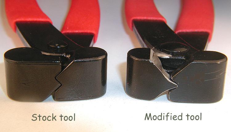
With these simple tools and a little bit of practice, you can form up to 90 degree bends in piano wire (even .078" diameter) and locate those bends to a tolerance of a few thousandths of an inch.
Now, let's begin:
1. Starting with a nice clean, straight piece of piano wire, measure off roughly 1-3/4” (this dimension is not critical, just don’t make it too short).
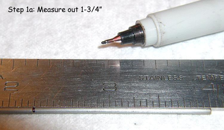
Bend 90 degrees. Tweak the bend to ensure it is 90 degrees.
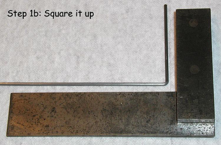
2. Lay the piano wire down on a flat surface and push your machinist rule into the inside corner of the bend. Measure and mark off the motor box width dimension (in this case 1-25/64") and bend 90 degrees.
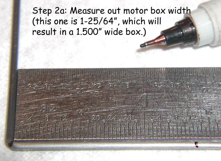
Tweak the bend to ensure it is 90 degrees, and that the now “U” shaped piece of piano wire lays flat.
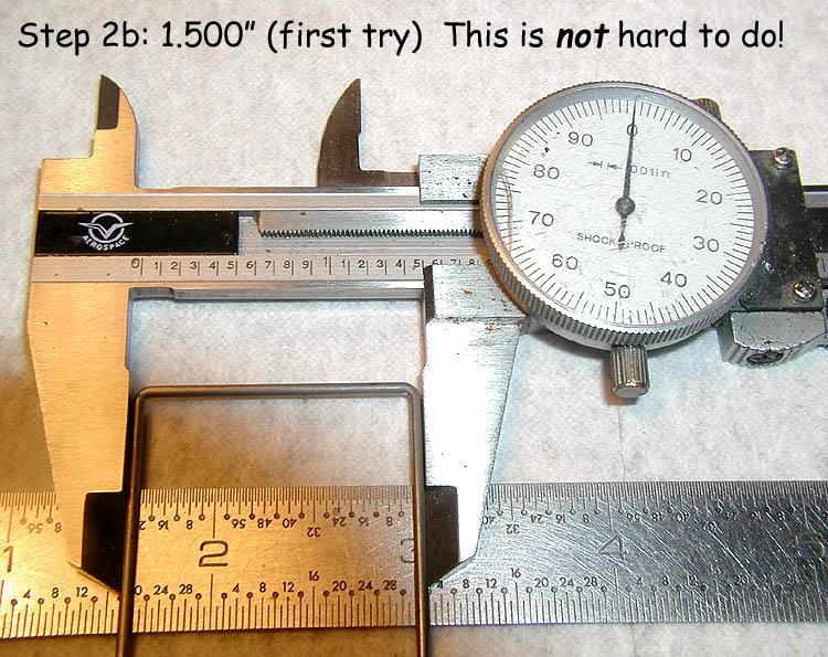
For an exact replica of the Emott Batwinder motor box, the dimension is 1-13/32” minus about 6 to 8 thousandths, and the finished outside dimension will be 1.512”, plus or minus not more than a few thousandths.
Technical note: Geometry of Bends. Since bends cannot be zero radius, the process of forming the bend wraps the material around the radius of the bending tool, thus “using up” some amount of material and shortening the distance between the bends.
In other words, if you take a straight piece of 1/16” piano wire and place two marks exactly one inch apart, then make two facing bends, one at each mark, the inside distance between the two “legs” will be less than one inch, probably about .026” (.013” for each bend) less.
Until you have the exact dimension worked out, you must generally guess at how much forming the bend will subtract from the length of the finished piece, and add it back in before making the bend.
Fabrication note: Since the goal here is to simplify, accelerate and make the process more accurate all at the same time, I always make a bend, measure, make another bend, measure, etc. instead of making all the marks first and then making all the bends. It reduces the additive errors to such an extent that I strongly recommend you do it the “bend / measure / bend” way.
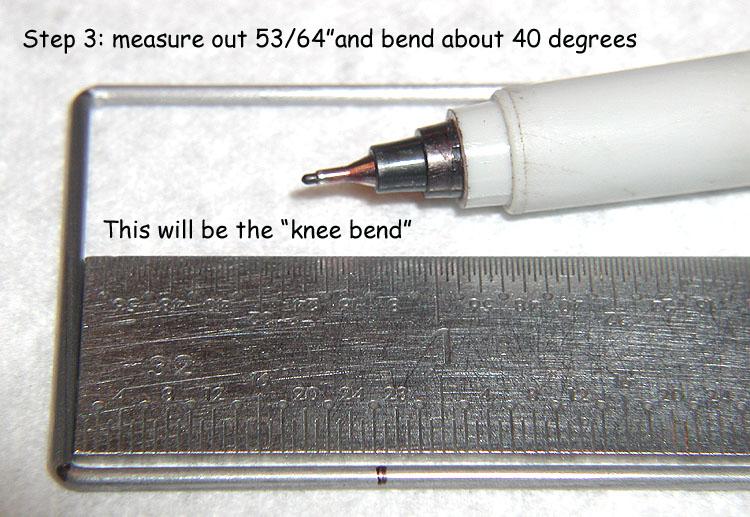
3. Lay the piano wire down on a flat surface and push your machinist rule into the inside corner of the second bend. Measure and mark off 53/64” and bend about 40 degrees. This dimension is fairly critical (it locates the knee bend and keeps it from interfering with the rear tire). The amount of degrees of bend is not critical just yet; we will tweak the bend later to get it perfect, so for now just make it about 40 degrees. Check again to see that your motor box lays flat.
Fabrication note: My machinist rule is thick enough (.040”) so that it does not “slip under” the piano wire I'm trying to measure. When you buy a machinist's rule, try to get one that is at least .040" thick. Also, although I routinely measure and mark to a tolerance of 1/64”, I rarely use the 1/64” scale! Instead, I use the 1/32” scale (because it’s a lot easier to see) and measure my 1/64” dimensions in between the 1/32” scale marks.
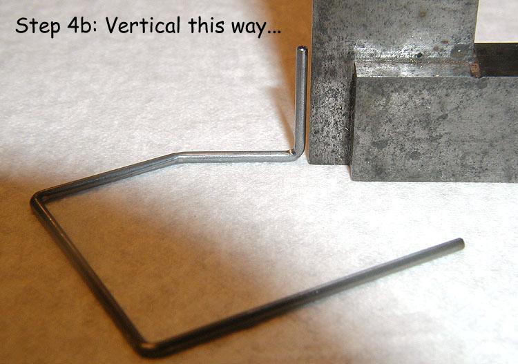
4. Lay the work piece down on a flat surface and place the corner of your machinist rule into the inside corner of the knee bend (from the previous step). Measure and mark off 21/32” and bend forming the vertical upright. This dimension is also fairly critical (it locates the upright and “sets” the number of degrees of finished motor box angle).
Cut the motor box off the stock material at about 5/8” to 11/16” from the upright bend. Check to see that your motor box lies flat, and tweak the bend to ensure the upright is vertical (I use a square and check in both the “X” and “Y” directions).

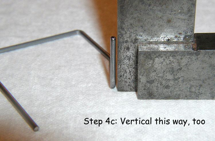
5. Go back to the original 1-3/4” leg (from step one), and push your machinist rule into the inside corner of the first bend. Measure and mark off 1-5/64”. Bend “UP” (90 degrees) and “IN” (about 20 to 30 degrees) as shown in the photo. This is another critical dimension (it “sets” the range the motor can move to get a good gear mesh and number of degrees of finished motor box angle).
Check to see that the tilted upright is roughly in the same “plane” as the other upright, but tilted inward about 20 to 30 degrees. We will tweak the finished angles later.

Fabrication note: I recommend you “tin” the finished motor box at this point, and then go back and re-check and re-set your bends; heat has a way of causing them to shift around. The good side to this is that after those bends have shifted once due to the heat applied by tinning, they generally do not shift any further.
The finished motor box is now ready to be fitted and attached to the rear axle tube.
6. Cut some 9/32" axle tube to 1-1/16" long.
Assemble your tube, axle, bearings, spacer washers and gear such that the outside dimension (over the bearing on one side and the gear on the other) is 1-7/16” with a tolerance of plus .016”, minus zero.
7. Now we fit the motor box to the rear axle. Photo 7a illustrates (on my jig block) the critical proportions and dimensions for locating the motor box in the chassis so the main rails will flow around it smoothly. You don't have to draw this out on your jig block if you don't want to, but I find it very useful in placing the motor box precisely. Note this will work for both left and right hand drive.
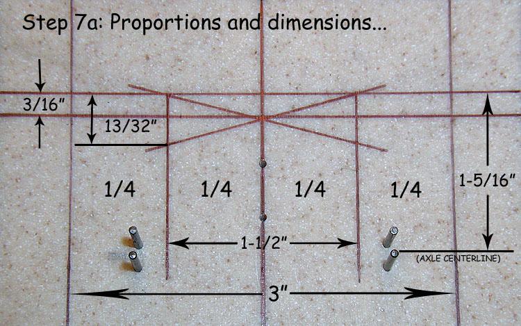
Place and center the axle tube assembly (with jig wheels) in the jig block. Now place the finished motor box in the jig, up against the rear surface of the axle tube. The forward most extent of the motor box should be very close to 1-5/16” from the rear axle centerline, and the furthest gear side extent of the motor box should be 3/4” from the centerline of the jig block, as shown in photo 7b.
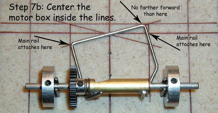
As long as the vertical upright opposite the gear-side remains vertical, you can tweak the knee bend (from step three) to set the furthest forward extent of the motor box at 1-5/16” from the axle centerline.
With the motor box positioned so that the furthest gear-side extent is 3/4” from the jig centerline (as shown in the photo), you can tweak the gear-side tilted upright (from step 5) so that the motor box angle matches the angled line (14.5 degrees).
If you located the bends precisely enough, you won't have to do anything at all and it will fit as in photo 7b.
When you're happy with the fit, solder the motor box to the axle tube, and you're done!
Now the tapered outer main rails will be centered and will fit with only one bend at the motor box:
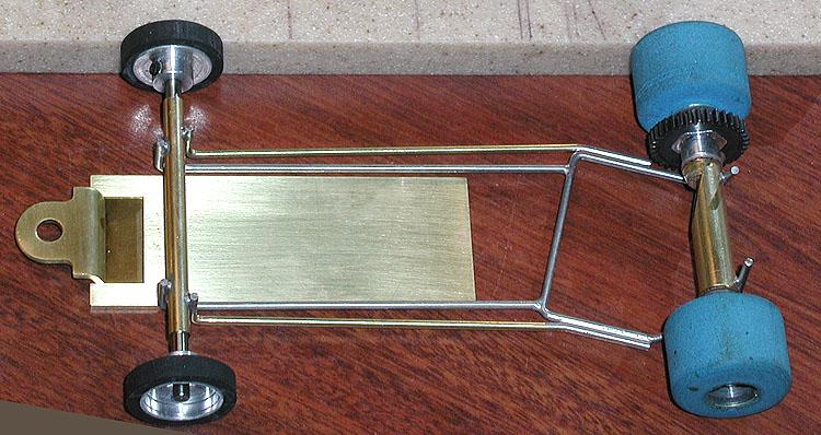
Piece-O-cake!


