


Hammerhead Thingies
Page 3
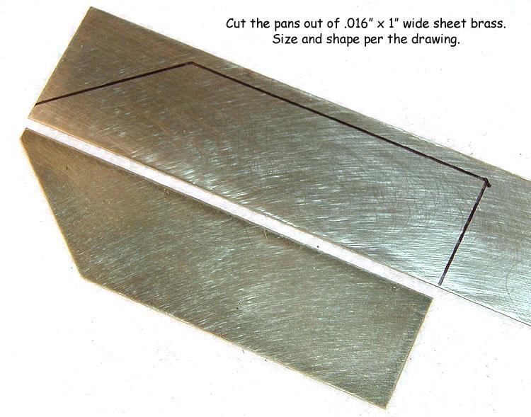
Cut the pans out of .016" by 1" (0.4 x 25.4 mm) wide brass strip. The exact size and shape is shown on the drawing. Normally, I would use a nibbler but here I've chosen to cut with a Dremel and file to finished shape because there's less chance of warping the material. It must be F-L-A-T.
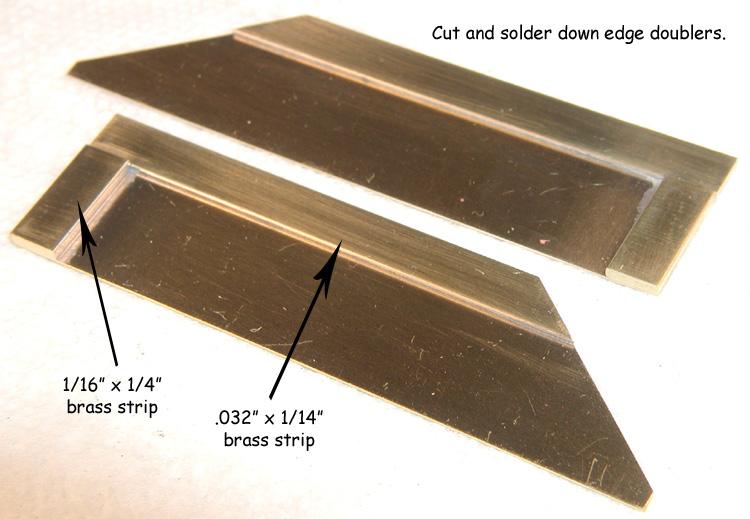
Cut some .032" by 1/4" (0.79 x 6.36 mm) brass strip to act as a doubler and solder it flush with the outside edges of the two pans. Do the outside edge doublers FIRST... Now, cut some 1/16" by 1/4" (1.59 x 6.36 mm) brass strip (for weight) and solder it flush along the rear edges of the pans. Neatness counts!
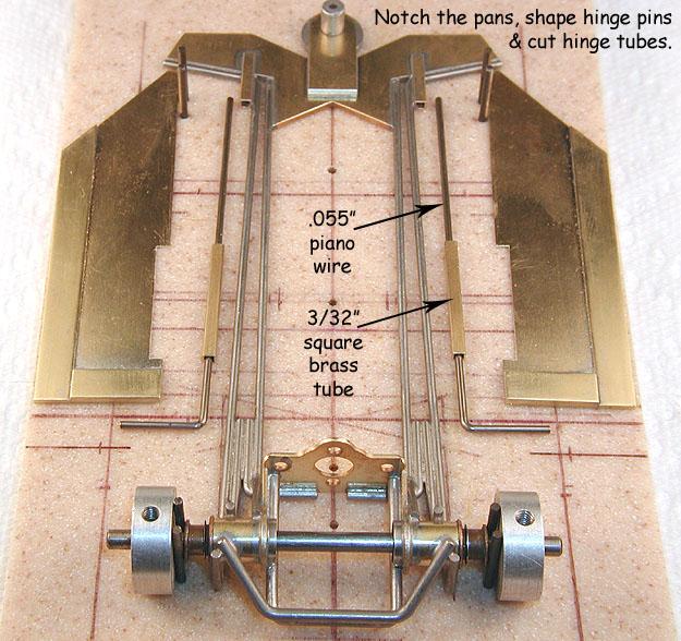
Shape some .055" (1.4 mm) piano wire hinge pins as shown. Leave them a bit longer than necessary for now. Cut two pieces of 3/32" (2.38 mm) square brass tube 1" (25.4 mm) long and slip one each over the two hinge pins. Position the pans on the chassis and the hinge assemblies on the pans.
Place a short piece of 1/16" (1.59 mm) rod up against the front surface of the rear pan weight to act as a spacer, and the hinge pin up against it. Slide the hinge tube up against the bend in the hinge pin and carefully mark its position with your Sharpie marker. Mark the hinge pin length so it will fit into the pocket on the nosepiece. Repeat on the other side.
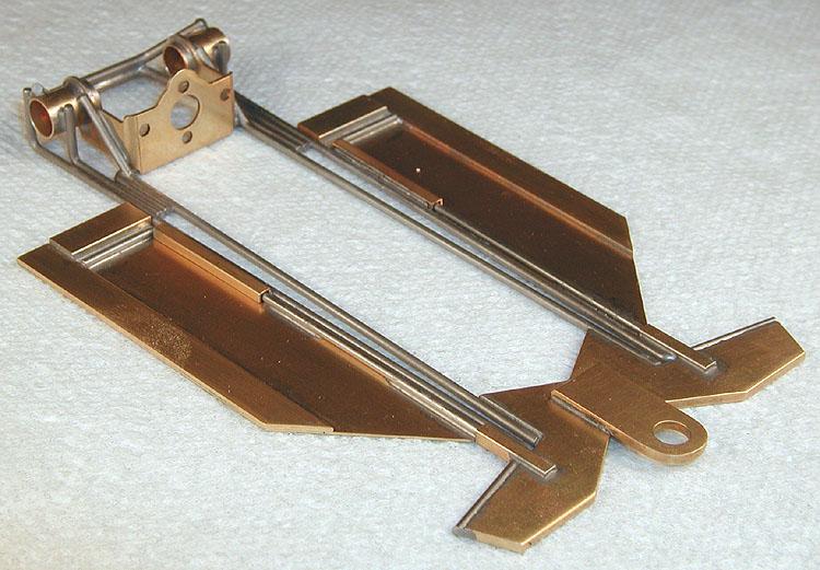
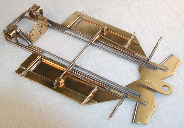
Now, notch out the pans to fit the square hinge tubes, and trim the hinge pins to fit into the pockets. When you are done, the parts should look like this:
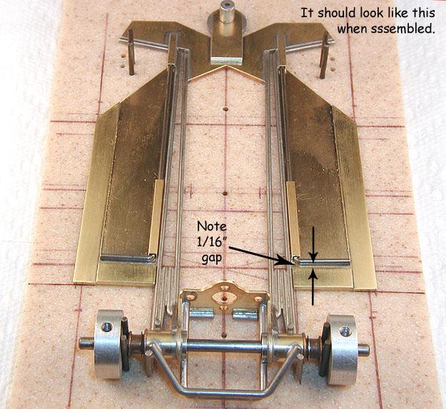
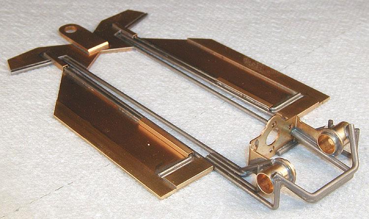
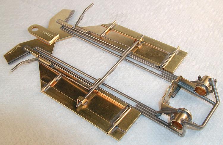
When you assemble the parts, it should look like this:
Now, solder the hinge pins to the pans. To discourage solder from wicking into the hinges, I place a tiny drop of lubricating oil into each end of the hinge tubes. I solder the "L" first (right behind the hinge tube), then in front of the hinge tube, and then last at the front near the nosepiece pocket. HINT: Allow the whole assembly to cool between each solder joint; it will reduce warping...
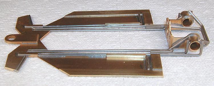
When you're done, it should look like this:
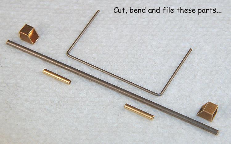
Next we do the side pan hanger cross bar. You will need .032" (0.79 mm) and 1/16" (1.59 mm) piano wire, some 1/16" (1.59 mm) round brass tube and some 5/32 (3.97 mm) square brass tube. Cut, bend and file as shown... lots of little parts!
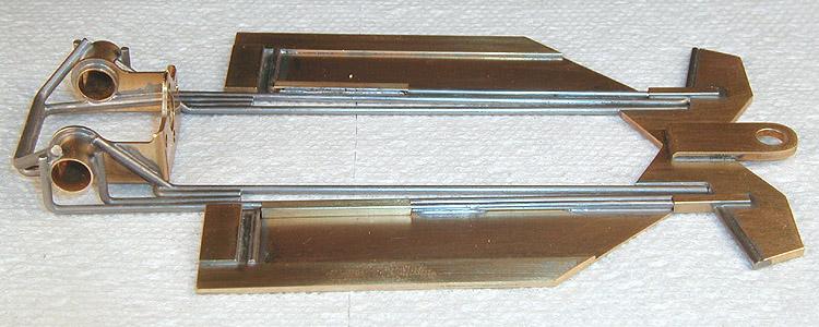
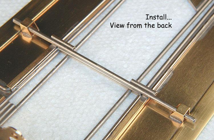
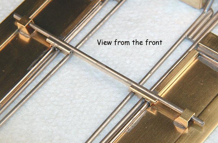
Solder down the cross bar first, the round brass torsion spring anchor tubes second, the piano wire brace third, then top it off with the square brass tube pan hangers. When you're done, it should look like this:
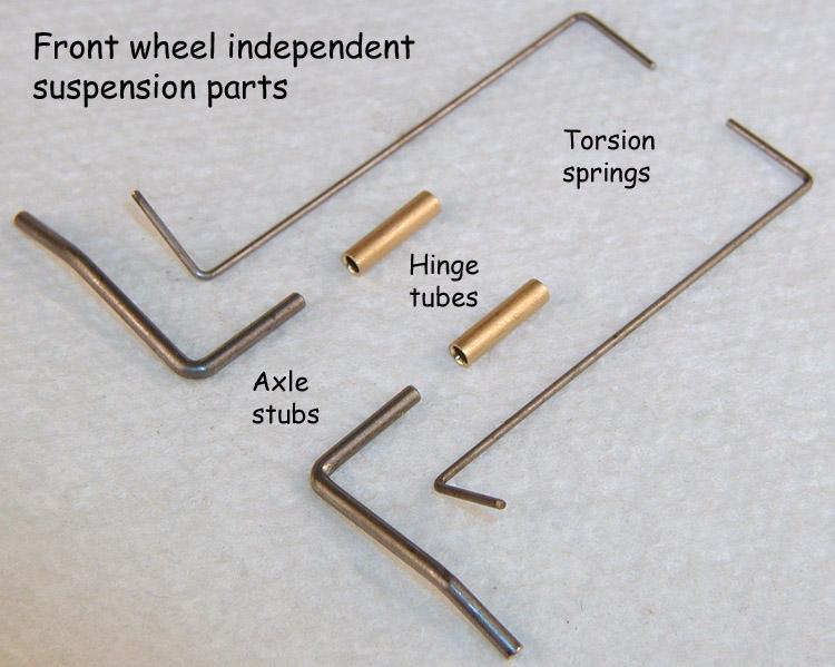
Next come the independently suspended front axles, using simple but effective torsion springs. Make up these parts using .032" (0.79 mm) and 1/16" (1.59 mm) piano wire and 3/32" (2.38 mm) round brass tube:
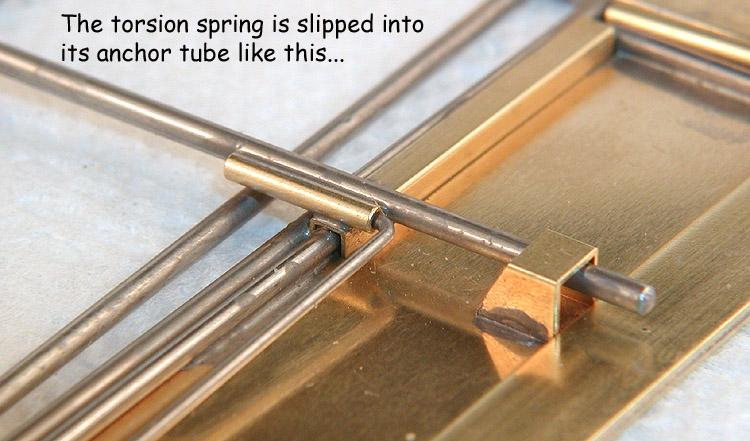
Insert the axle stubs into the hinge tubes with some lubricating oil to discourage solder from wicking into the hinge. Place these assemblies on top of the side pans and position them to provide the correct wheelbase. Solder down the tubes and remove the axle stubs. Slip the torsion spring into the anchor tube soldered to the pan hanger as shown here:
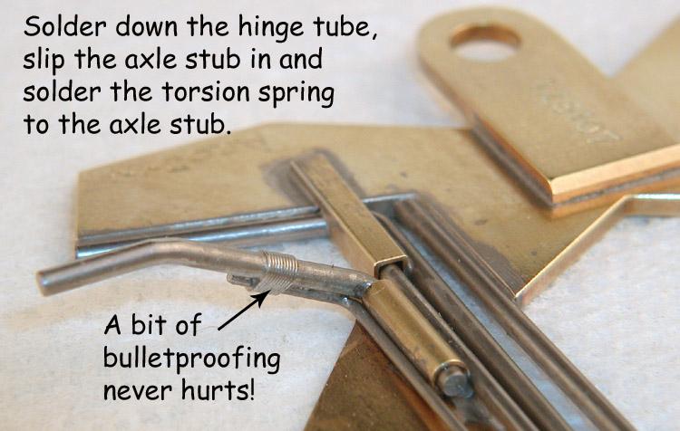
Reinsert the axle stubs so that the torsion springs are underneath them and tie (bulletproof) the torsion springs to the axle stubs. Set the axle stubs with jig wheels, lubricate the hinges again, and solder the springs to the axle stubs:
All that's left to do now is to cut and install the body mount pin tubes. The rear pin tubes go into the 1/16" (1.59 mm) gap between the side pan hinge rod and the rear pan weight.
Here's a roller from an earlier build. It has 3/4" (19.5 mm) fronts and .790" (20.1 mm) rears.
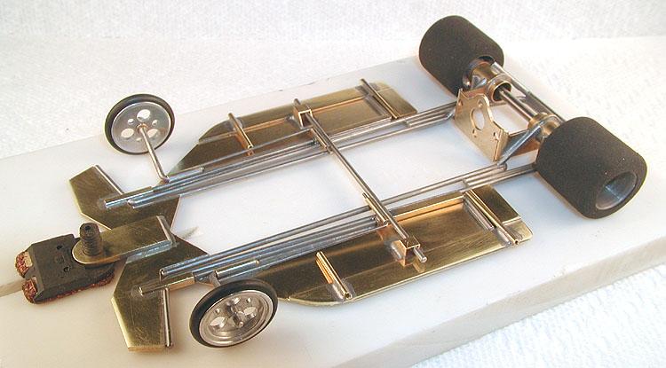
With a powerful motor (maybe 26 gauge wire?), this should be a rocket!
I had an even more radical notion for the floppy hinge system, and built a modified center section to test the idea. You'll find that one on the next page... (Click here)


