Thingie Tyro
By Steve Okeefe
Back in 1967 and 1968, "Thingie" slot cars were a fad within a fad, and became a whole separate and distinct class of cars. Their origins lie in the pursuit of road course straightaway speed at any cost, and the novelty of artistic, sometimes cartoon-like (although rarely functional) aerodynamic streamlining, leading to the almost complete abandonment of the notion of building a scale model race car.
"Thingie" bodies could be utterly outrageous, but their chassis tended to be simple affairs. Early ones (circa 1967) usually had drop arms but nothing else, as the hinged body mount, or side pan, had not yet made its appearance, and the anglewinder revolution was almost a year in the future. Some of the more sophisticated Thingie chassis were patterned after the Cox La Cucaracha, having an Iso Fulcrum hinge located somewhere close to the rear axle.
This build is an Iso Fulcrum Thingie with inboard hinged side pans, shaped to fit the Electric Dreams Shinoda Bullet body. While not a replica of anything in particular, it is nevertheless a serious attempt at designing and building a "period correct" Thingie chassis.
Also, this is an early version, which has typically narrow O-ring pinhole wheels and integrated side pan up stops. A later version has wider pinhole front wheel hubs and separate up stops. More on that later.
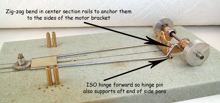
The center section alone:
The single 1/16" (1.59 mm) main rails (later found to be too flexible), attach to the motor bracket using a "zig-zag" bend and solder joint. The idea here is to make the joint not only longer (and therefore stronger), but to arrange it in such a way that the joint in one direction naturally braces the joint in the other direction.
The forward mounted Iso hinge tube braces the motor bracket, and the hinge pin, extended to become the outer rails of the Iso section, will support the aft end of the side pans (not yet installed).
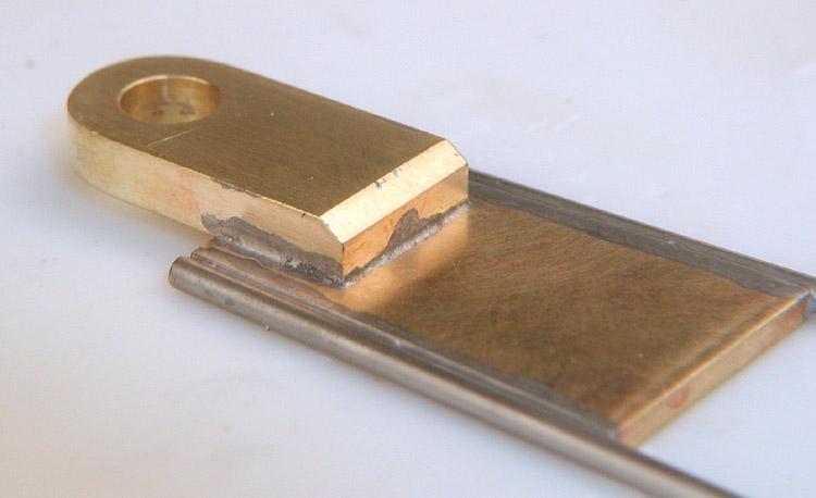
The guide tongue is cut and mounted:
The guide tongue is 1/8" (3.18 mm) thick brass. I did this to add strength to the part and weight to this critical location.
Here I've added the motor bracket braces:
On this earlier version the top brace is 1/16" (1.59 mm) piano wire, and the bottom brace is .078" (1.98 mm). On a later version, I used .078" for both braces.
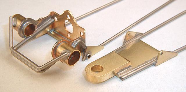
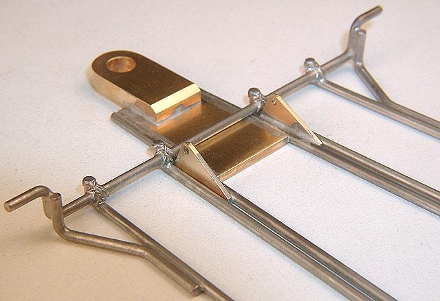
Here is the center section with .032" (0.79 mm) brass gussets installed:
The rear gussets tie the Iso Fulcrum hinge tube to the main rail, and provide a rear mounted spacer for the Iso section to be added next. The front gussets act, with the addition of a piece of .047" (1.19 mm) piano wire, as an up stop, and also as a front mounted spacer for the Iso section.
Here the ISO section has been added (no side pans yet).
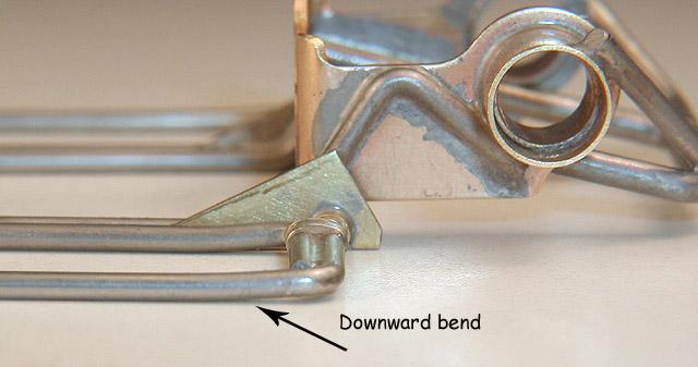
Front end. The drop axle attachment is thoroughly bulletproofed, and the main chassis down stop also serves to prevent sideways movement between the two main chassis sections as they move up and down.
Don't forget to put that "kinky bend" in the ISO section rails to bring them down flush with the bottom of the chassis.
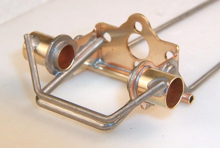
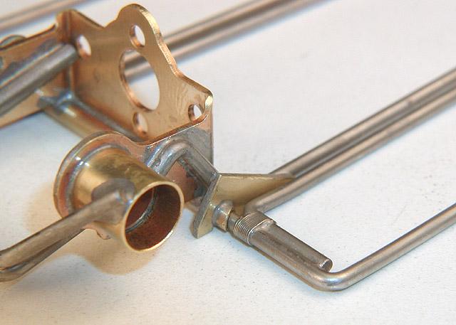
A detail shot of the main ISO hinge from the top:
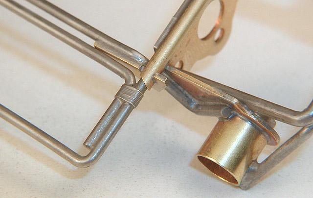
And from the bottom:
The little triangular brass gussets also serve as "rub strips" to prevent sideways movement between the two main chassis sections.
Shortly after I posted photos of this build, I got a PM from Greg "Cheater" Wells suggesting, ever so gently, that I might find he center section was going to be too flexible in "beam". The concept of "beam", and its role in the way a chassis handles, is widely understood, although the word itself may not be familiar (it wasn't to me).
Quick review: If you support a piece of piano wire (for example) at its ends, and press down in the middle, the direction in which the bending and flexing happens is called "beam". Not enough beam strength and the chassis will behave poorly, and there is little or nothing short of increasing beam strength that will fix it.
Having never built an Iso Fulcrum Thingie chassis like this one (surprise!), it only occurred to me afterwards that there might be a problem here. I had tried to keep the two center section rails as short as possible, to limit flex, but it apparently wasn't enough. When Greg pointed it out, I decided to check it out myself against some chassis of more conventional design.
Well, the results are in: This is definitely going to be a problem, and needs to be fixed!
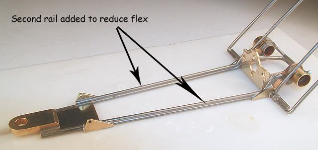
Here's what I did; I added a stiffener rail to each side, stacked on top of the existing rail:
Now the center section is stiff as a board, much better!
Next up, sidepans... (Click here)


