What If We Had Listened
To Mike Morrissey?
By Rick Thigpen
Car Model articles re-formatted for improved readability March 2013
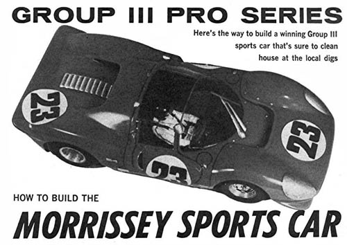
I was looking thru the July 1967 issue of Car Model Magazine I’d just bought off eBay when I came across this column by Mike Morrissey. Take a gander:
How would a So-Cal 1967 Pro car run using Mike’s guide lines? “I just gots ta know!” I’ll bet there were other groups somewhere running more scale tire sizes but I’ll be applying them to a Car Model style Pro car.
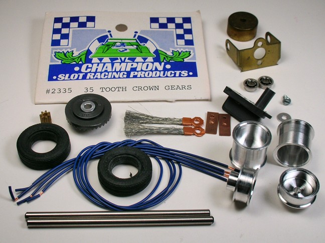
I’m still deciding on a 1967 chassis style and motor but here are the parts I've chosen so far:
Replica Russkit front and rear wheels (the rears are the exact 9/16" Mike called for). Monogram 1/32 scale model kit rear tires for the front wheels give a nice 15/16” diameter (EJ's "Revell style" tires would also work but they'd be 1/64" under sized).
Modern drill blank axles and 1/8" ball bearings get the nod.
The REH crown gear might still be available. That's why I showed the package with part number. It is a Weldun gear with the name removed. REH "multi nimble" lead wire, a Cox guide and a "mystery" vintage 7T brass pinion round out the parts list.
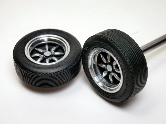
OOPS! Those narrow front tires will never do. 3/8" wide they need to be. Old habits die hard! OK, how about this for fronts.
They are Russkit "Rear Road Wheels" and Monogram 1/32 scale wide rear tires off the GP car. They are a perfect 15/16" diameter but they are a little narrow.
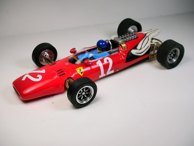
Here is a typical 1967 Car Model type car:
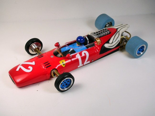
Here's a mockup of what Mike proposed. The rear wheels and tires are correct diameter but a little narrow:
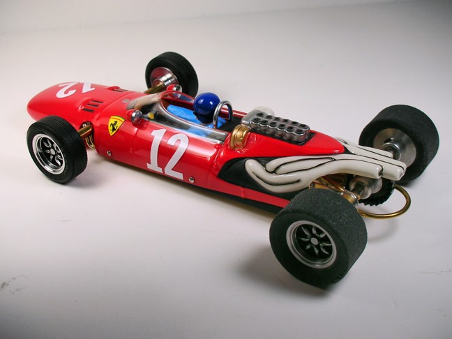
Hmmmmmmmmmmmmmmm. I was going to build a sports or GT car but maybe it should be a GP. Hmmmmmmmmmmmmmmm…………No, let’s do this:
To see the entire article… click here
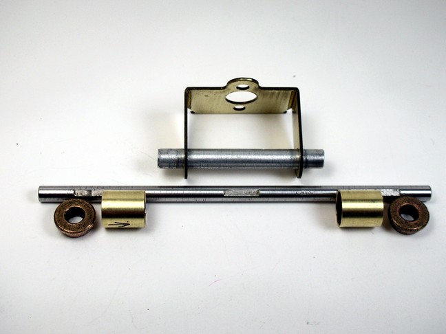
It’s time to start building. I'm going to use 1/4" ball bearings in the Russkit bracket. Mike used this technique in a construction article a few months after this one.
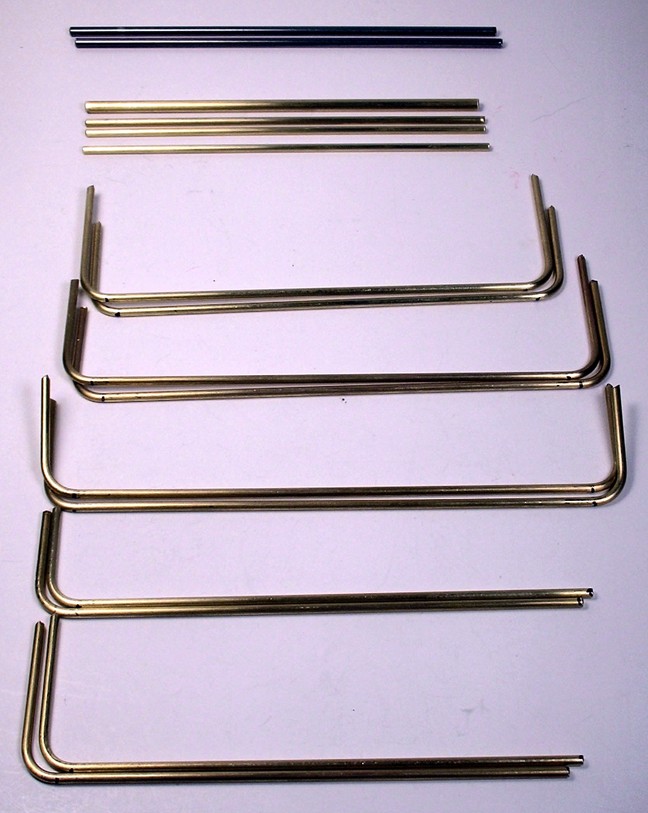
Here are the "parts is parts":
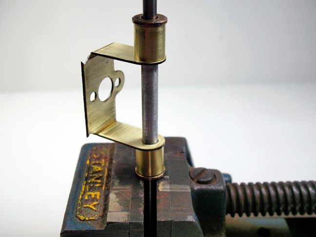
The 5/32" aluminum tube in the bracket holds everything in alignment thusly:
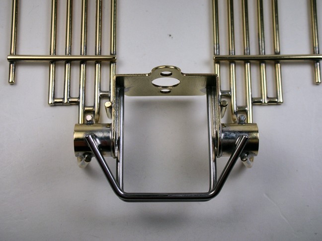
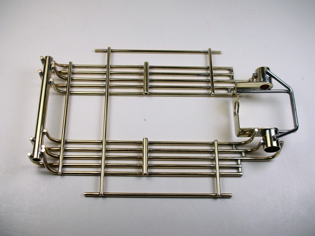
I cut and bent everything before I started soldering:
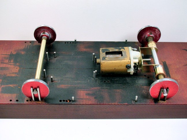
Now the motor, bracket, front axle tube and jig wheels are placed the chassis jig:
What the heck are all those pins sticking up all over the place for? That's the best part of a chassis jig. A place for everything and everything in its place.
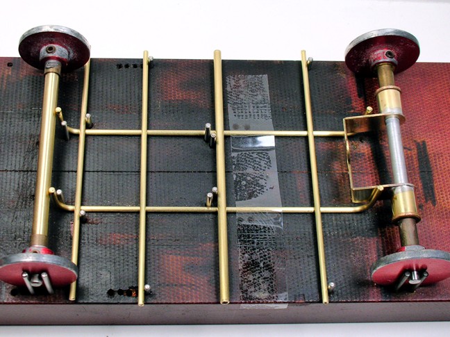
All the cross pieces are left long and held in alignment by pins in the jig. The first 2 main rails are also spaced and aligned by pins:
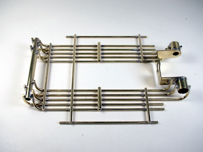
Here's the chassis all soldered up with the extra junk trimmed off and a little coarse polishing:
This is the first time I used the "Magic Gizmo" (thanks Steve Okeefe!) to bend the rails. It was really made to get the "kinky" out of bending tube but I decided to use it on this rod chassis because I like the way the big radius bends look. They are all perfectly uniform:
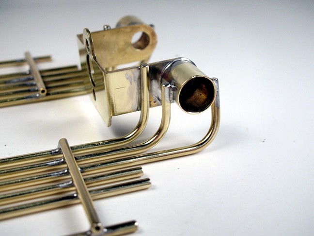
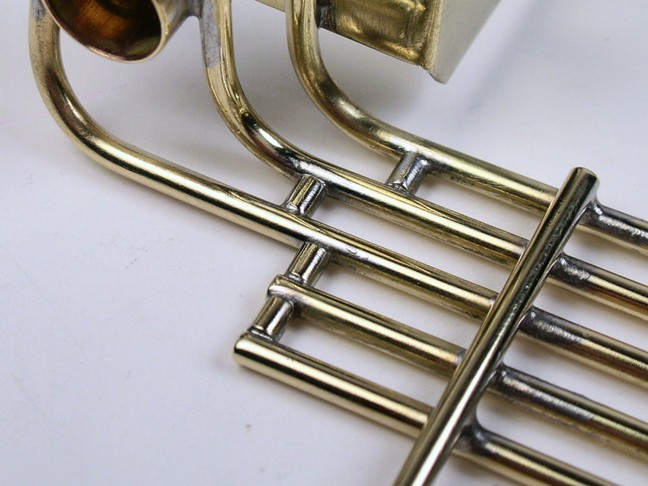
I installed the 8 little .080" long "gizmos" that tie the back of the frame rails together:
The really cool way to have done these would be to cut a radius in each end to match the frame rails. I made one, thought about the other 7 I still had to make and threw it away.
As you can see mine are just straight cut pieces soldered in place.....AND I sanded the pee out of them. Maybe a mini torch or a smaller soldering iron tip or just a better craftsman wouldn't need to but I'm not unhappy with them.
They look better in real life when they aren't blown up a zillion times. Here's another shot along with the rear axle braces. I did mine differently than Mike did. Sorry Mike but I like this better.
Here's the chassis awaiting construction of the drop arm:
Article continues on page 2


