This frame will be built at 1.625" width and will use the cut-down JK Can-Am nosepiece that I resurrected from the earlier car. This build would be legal in the west but not for the IRRA™ rules. However, the same build could be done around the fine JK F1 kit and all the steps would be same save the rail spacing and width of the forks.
The first step is to decide on your bracket of choice and what nosepiece to use, whether to use a pre-fab or to go scratch, and then where you want the forks to go (inside the bracket legs or outside. Then, you’ll lay out your parts and decide where you want the rails to go and what size you’ll use.
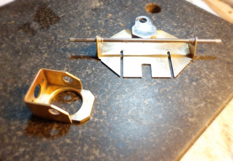
This shows a 3/4” Warmack bracket and the salvaged JK nosepiece. I have cut a bracket plate from .093" brass to fit inside the bracket, then drilled a 5/8" hole in the plate to clear the gear. Center the hole right under the axle.
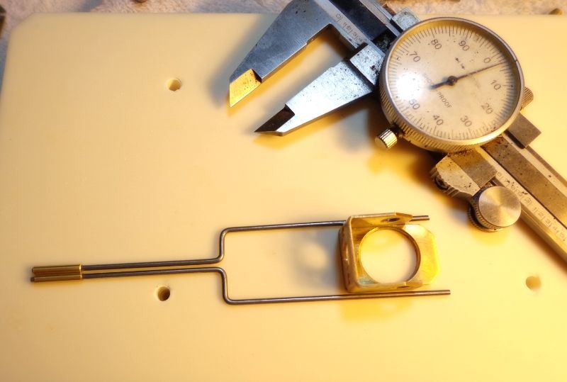
Here is the bracket laid out on a flat block with the fork rails laid in place to check the spacing. This also gives you an idea of how your rails will fit. Bending the fork rails isn't as tough as I thought it would be. Just use good square pliers and you won't lose much in the bends. In this case I bothched one so I had to bend three to get two. That’s been about my average so far. These are pretty good but rear leg of the near side rail needs a little work.
Now, into the jig. This is an R-Geo jig that has some features that I really like for this build. Besides, it’s just flat and square and very precise, the way a jig should. Here, I have the nosepiece in place, the forks are in place, and the front tubes are in place. Now is the time to check for square and to make sure everything fits. Try to get the fork rails as parallel as possible and as flat as is reasonably possible. Keep in mind, the pivot tubes will hold the rails up a little so completely flat isn't possible. When you’re happy, a quick tack of the pivot tubes to the nosepiece and the rear legs of the fork to the bracket. Triple check for square and that the forward fork rails are free and not binding.
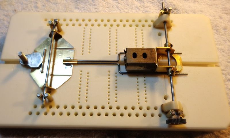
Next, we lay in the main rails and this is the key part of this build. The mains are .062" wire mounted in pivot tubes at the rear of the chassis. You want these rails to go straight and drop right into the slots in the nosepiece. It will take a spacer rail between the rear fork leg and the rear pivot tube to do this right. In this case .055" spacer rails provided almost perfect spacing so that the main rails were very parallel. In this pic, the rails on the right are in place and ones on the left are held so you can see how they fit. Once everything is in place front and rear, solder the spacer rails and the rear tubes in place. Don’t solder the main rails in yet.
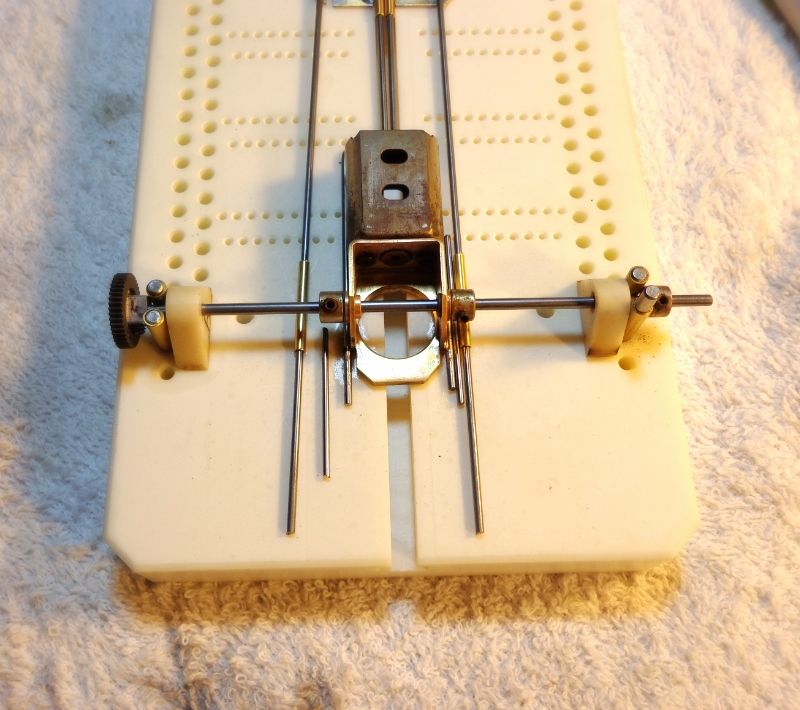
This pic shows the main rails with little caps of 3/32" tubing soldered in place as retainers. Build these outside the frame so that there is no danger of soldering up the rail in the tube. Leave the front a little long so you can cut it to fit. With the caps on, slip the rails through the rear tube, slide forward as far as possible, and cut the excess off at the front. Make sure it's all free and solder the main rain rails into the nosepiece. There is a little piece of .039" wire on the outboard side of the main rail to reinforce the solder joint. At this point, you have a completed center section. Check for fore and aft slop due to the opposing hinges and tighten up as much as possible.
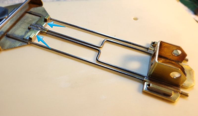
This pic shows a contingency plan. What you see pictured is an optional minor main rail. This would go as shown (more or less) and be soldered to the rear assembly and the nosepiece at the two blue arrows. This might be necessary for local rules but it also might be necessary if there is just too much movement between the fore and aft sections. This could also stiffen up the frame if it too flexible for your tastes. I suspect that I'll add this in on the first test day. My choice will probably be to make this out of .032" or .039" wire.
This is the finished center section with the rear pan tabs and pans cut and ready to go in. These are all 1/4” X .093" brass (remember... I’m seeking weight) The rear tabs have to be narrowed about .012" per side but the pans make the width as is.
All the shaker tubes are in place and are 3/32" square tubing. The front tubes are lifted on a piece of 1/4" X .026" brass (blue arrows); this to get the shaker tubes up above the pivot tubes and also flat on the thick pans. Note: .050" brass would have been a better fit for leveling things but I didn't have any.
OK... home stretch now. The whole frame goes back in the R-Geo jig and is lined up for width. This jig has holes for a stop pin at any width you could possibly want. I set the pins in at 1.625" and then used pieces of oiled paper to space the pans out to the proper width. This took about .006" per side. I think this is a key feature and not all jigs have it.(Congrats to Rick for thinking out the details.)
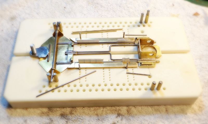
All the remaining bits are laid out to see. Two pieces of pin tubing, two pieces of .047" wire for the rear stops, and a bit of .055" wire for the front shaker (this could be .047" if you want more movement).
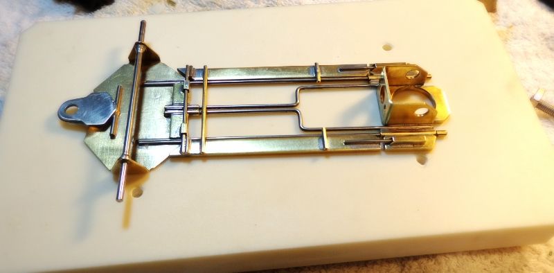
Having the stop pins here is a godsend because holding all these bits in place and the chassis, and the iron, can be a real fiddly step. In this case, you drop the pieces in place, go around the horn and solder them all up and... you're done. Here’s the finished product, ready for a little clean-up and final check for flatness and for pivot movement.
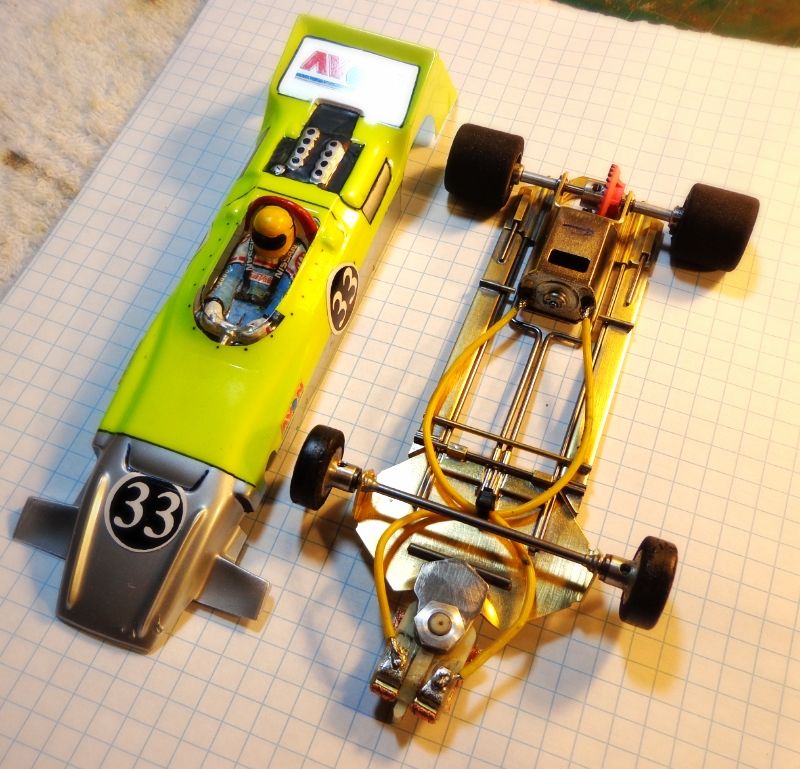
And... ready for the track. This car hits 103 grams without body, and has almost exactly the same flex as gen 1.0 but is much stronger. There is a little bit of movement within the tubes and this may cause wheel hop. If so, I’ll have the minor rails ready to go on the first test session. This is using S7 MB motor geared 8/29, JK 8713T tires narrowed, Swiss BB front wheels, and a Parma Matra body.
Ongoing testing reports and further developments will be reported in this thread. Development of some Can-Am prototypes or other general discussion will be continued in the exploring the tuning fork thread.


 Good question, right there...