Jump to content


Photo

Building the R-Geo "GVP" chassis


  • Please log in to reply
58 replies to this topic

#1 JimF

JimF

    Posting Leader

  • Full Member
  • PipPipPipPipPipPipPip
  • 2,220 posts
  • Joined: 20-June 07
  • Gender:Male

Posted 27 October 2013 - 11:03 PM

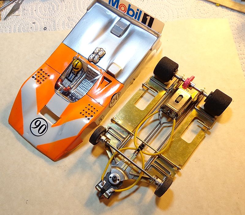
I just received this from Rick at R-Geo to build the justly famous "GVP" chassis. In a case like this, with a proven winning design, I'm not going to reinvent the wheel (or the chassis). This won't be an exact copy; it will be an attempt to remain faithful to the race winning design of the original. Any deviations will be in the interest of strengthening.


Because of my work schedule, I couldn't finish this tonight. I'm going to break this into two segments for the complete job. I promise that I won't drag this out over the next few weeks showing one solder joint a day or somesuch. Off we go...


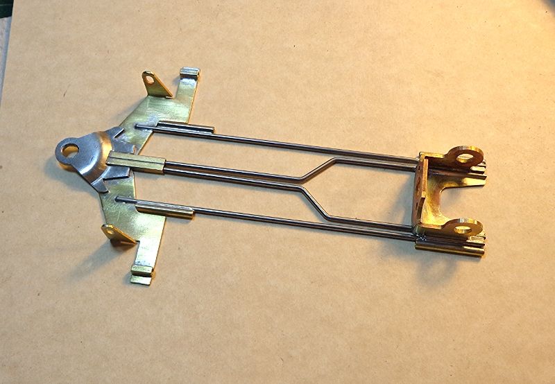
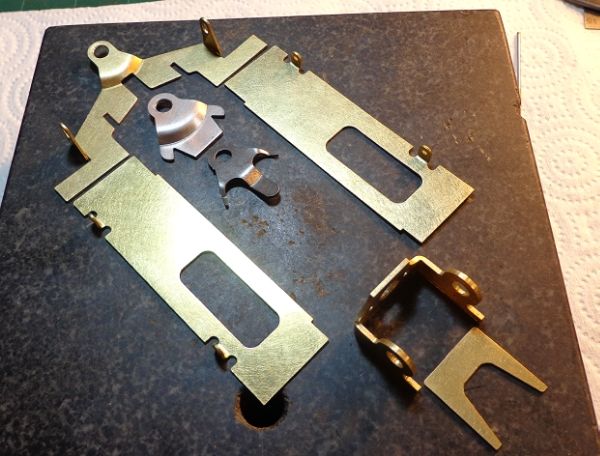
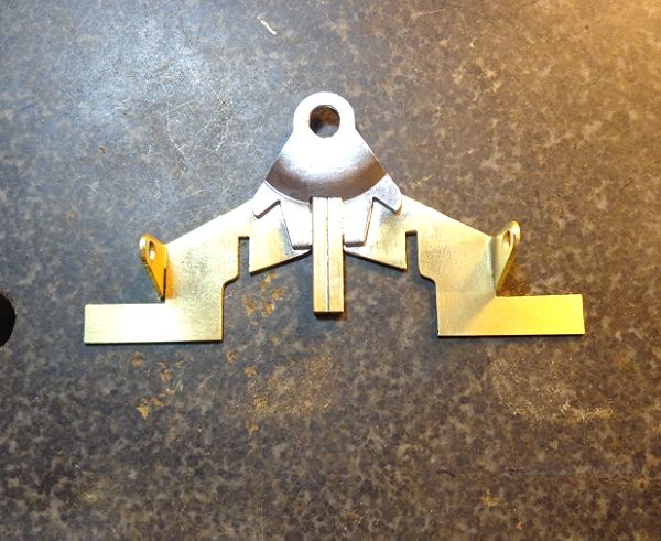
Here's what you get to start with. All brass is .032", bracket is .050". This is a nice builder's kit as opposed to some of the "Lego" kits out there.


e7f9c67b-e326-4df4-8874-35cde5f871cb_zps


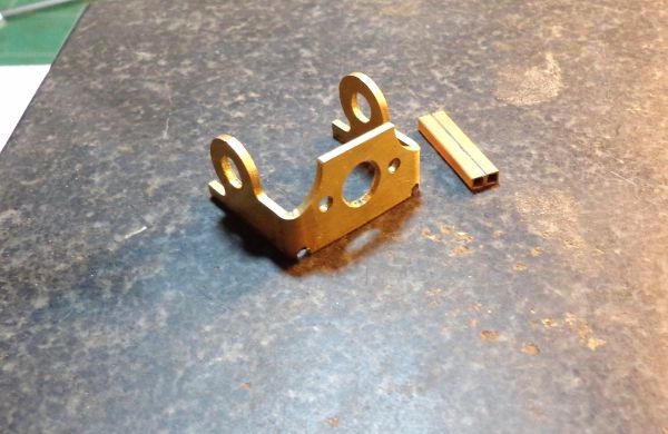
First step is to square and prep the bracket. This is basic stuff. The bracket face is filed until flat then the legs are bent square to the bracket face. The bracket is cut out slightly to accommodate the tuning fork rails which will run along the inside of the bracket. To the side are two bits of 3/32" square tubing about 3/4" long. These are soldered together and then dressed flush and square. These will be the fork hinge tubes.


2f443a7f-a98f-41f5-bd06-91277e6af1bf_zps


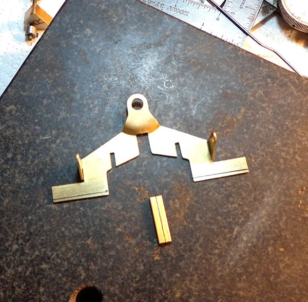
Here is the nosepiece with the hinge tubes. Lines on the ears of the nosepiece show they need to be sanded square or at 90* to the chassis centerline.


b022586b-d483-450c-a121-976f675d2982_zps


Nosepiece squared up and the guide tongue reinforcer is notched to clear the hinge tubes.


60ea4b34-73a4-4a5a-aa35-44938302546d_zps


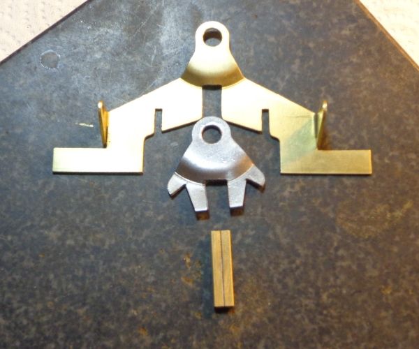
Here's the nosepiece with all parts tacked in place but not yet fully soldered.


d132e727-13c7-43ac-b51e-342b5f7175b7_zps


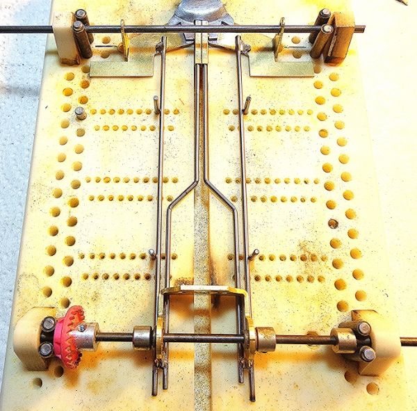
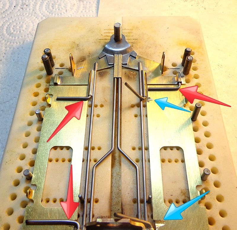
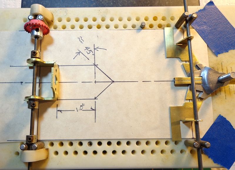
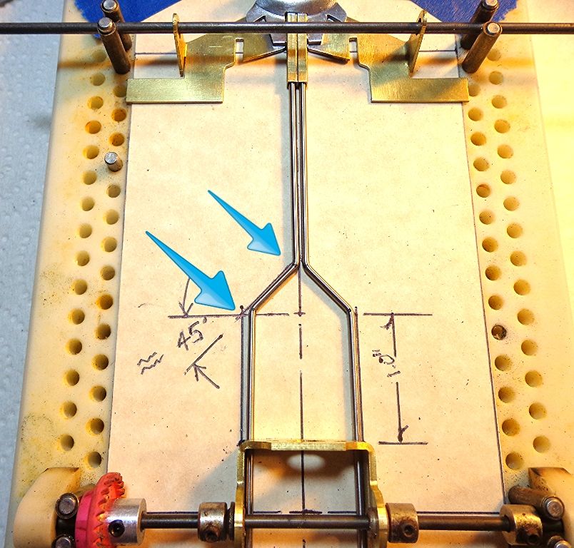
The nosepiece is dropped into your jig along with the motor bracket. The paper template underneath will be your guide for bending, placing, and adjusting the forks. The first bend in the fork will be 1" forward of the bracket face. Both bends in the forks will be 45*. Neither the distance forward from the bracket nor the angles are critical.


cfcd63ed-591b-40e2-b4b5-154fded178cf_zps


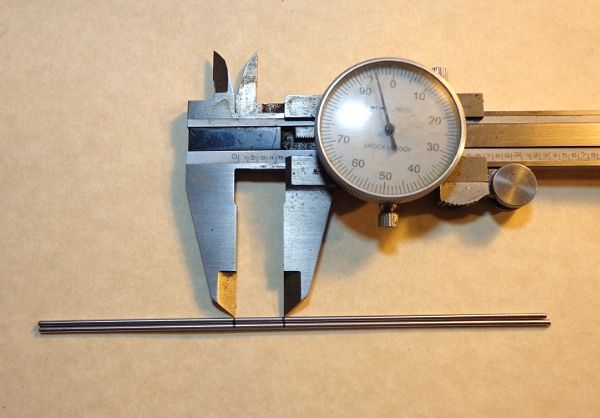
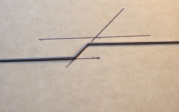
Take two pieces of .062 piano wire about 5" long, and place a sharp mark at about the 2.100" point. Then measure .495" forward of the first mark and make a second. These will be your two bend points.


bd90f10a-456a-4f0f-afaf-c0fcd22da62d_zps


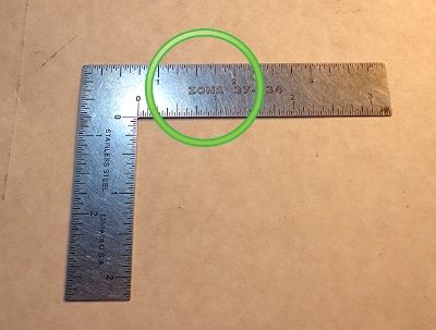
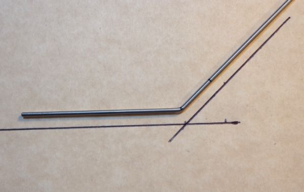
Make your first 45* bend. A little hand drawn template is handy here to check your angle.


e228a210-3141-4c92-b4d6-650c74cd8c6a_zps


Make your second 45* at the forward mark you made on the wire. Again, the template comes in handy to check that the fore and aft legs are as close as possible to parallel. You'll be surprised how accurately you can judge this by eye. After your bends are complete, your angles matched as close as possible, and the legs are parallel, slap this piece on a block and bend the legs until the piece lays flat. Then go back to the template and check the angles and the parallel again Repeat this process for the second fork rail.


4b29f5eb-44a4-4e81-94f5-ab4db7087bb3_zps


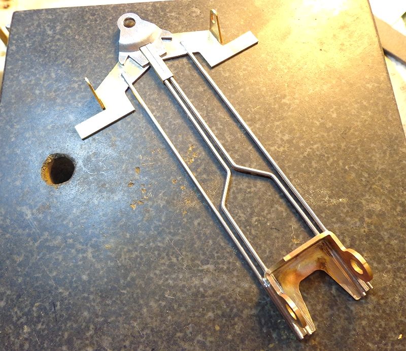
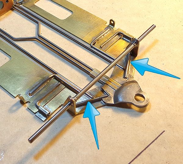
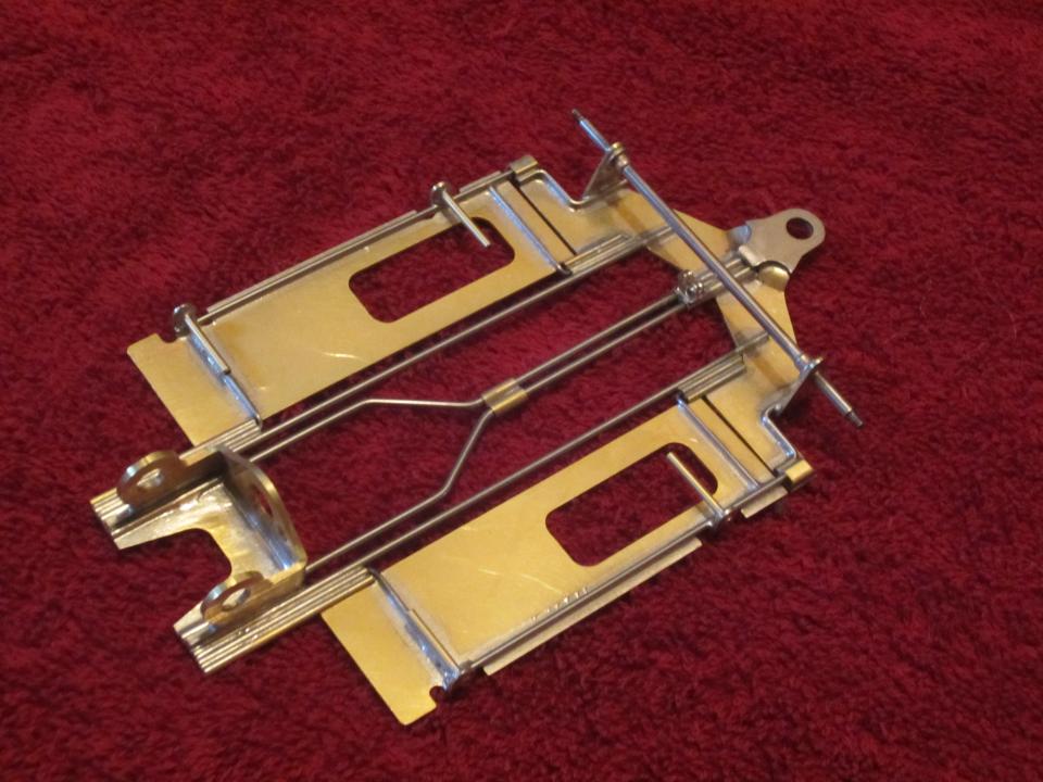
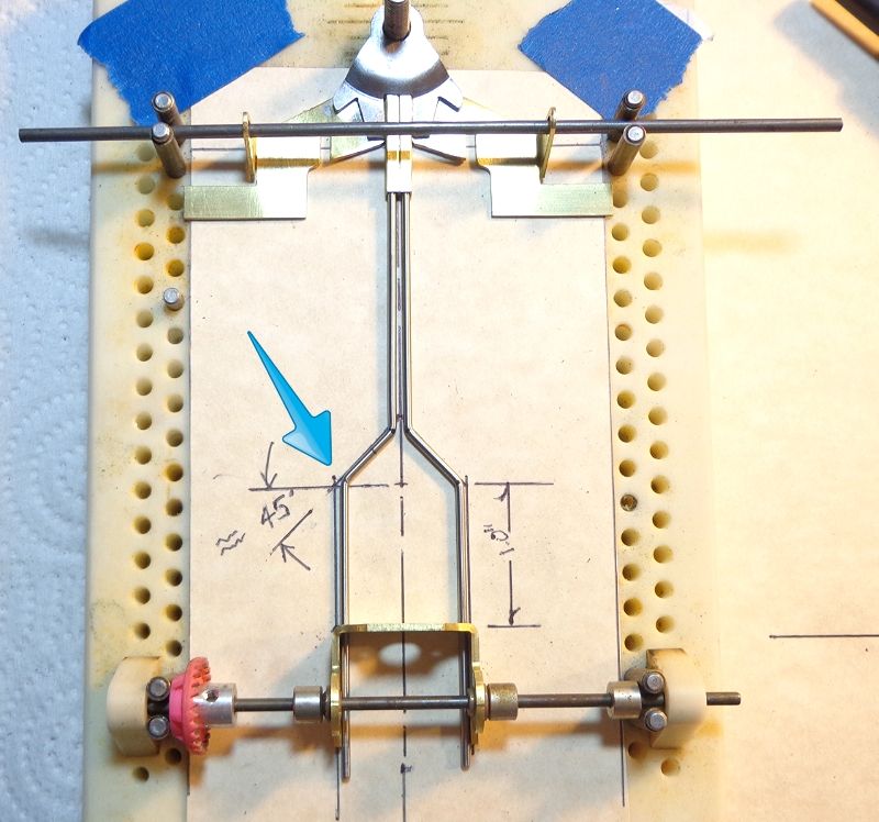
When both fork rails are bent, tweaked, flattened, and aligned, slip the forward ends into the hinge tubes and the aft legs inside the bracket legs and see how you did. The template paper will show you how well you hit the angles necessary and how well matched they are.


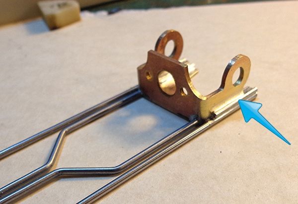
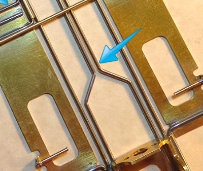
In this case, my right rail was almost perfect, but my left was off a little at the two points indicated.


f58aeafd-1c60-4bc3-b4f8-b9dc72d0f8a1_zps


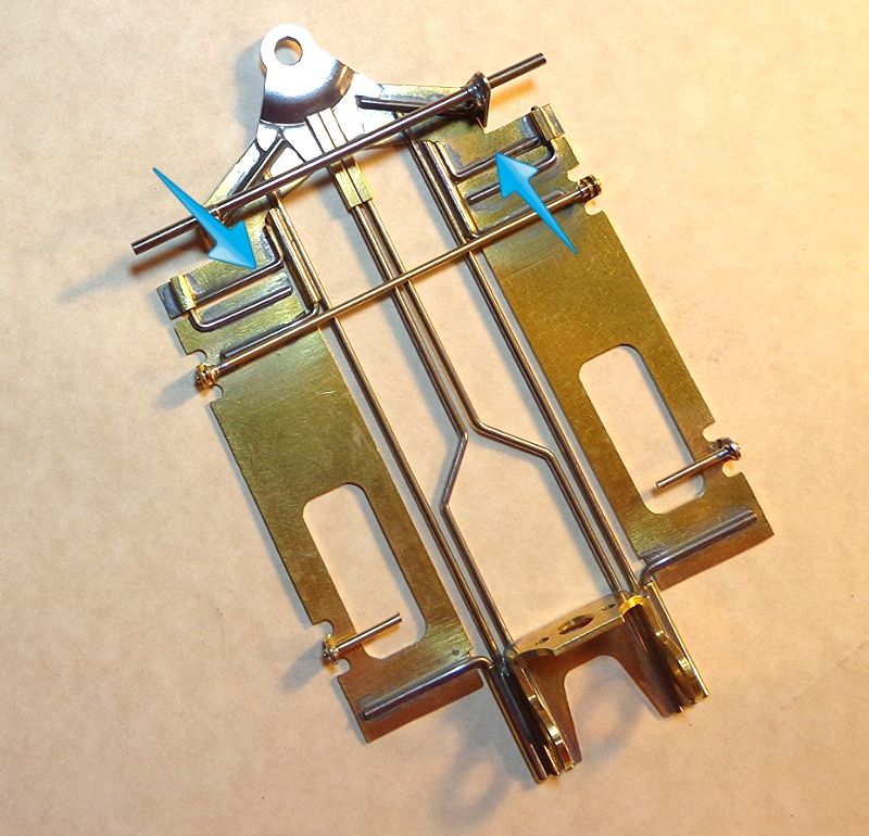
A little corrective bending got the left rail a lot closer as seen here. At this point, I could have just kept on bending and tweaking that rail but I decided to just bend another. The next one was spot on so I called it good and moved on.


eeabed54-6ece-4d5b-9eea-87abf91448f5_zps


That's the end of the first segment. Next up are the main frame rails, pans, some reinforcement, and finishing up.


  • Cheater, Tim Neja, jgntx830 and 1 other like this
Jim Fowler


#2 SlotStox#53

SlotStox#53

    Posting Leader

  • Full Member
  • PipPipPipPipPipPipPip
  • 4,084 posts
  • Joined: 13-March 13
  • Gender:Male
  • Location:TX

Posted 28 October 2013 - 12:31 PM

Very nice kit and a very good start to another informative and comprehensive build *how to* thread.


Good work, Jim.  :good: :)


#3 kvanpelt

kvanpelt

    Checkered Flag in Hand

  • Member at Peace
  • PipPipPipPipPipPip
  • 1,282 posts
  • Joined: 29-January 08
  • Gender:Male
  • Location:IL

Posted 28 October 2013 - 01:50 PM

What would those "Lego kits" be?


Kevin VanPelt
?/?/56-6/12/23
Requiescat in Pace


#4 James Grandi

James Grandi

    On The Lead Lap

  • Full Member
  • PipPipPipPip
  • 473 posts
  • Joined: 31-May 10
  • Gender:Male
  • Location:Cranston, RI

Posted 28 October 2013 - 02:07 PM

One question; is it a necessity to use square tubing for the fork rails to fit into, or would round tubing be fine?
James Grandi
obSCEne Chassis
HVR BB Fronts
Bodies by Weaver

"There is no such thing as a race you are destined to lose. You will always have a chance."
 

#5 Ramcatlarry

Ramcatlarry

    Posting Leader

  • Subscriber
  • PipPipPipPipPipPipPip
  • 2,946 posts
  • Joined: 08-March 06
  • Gender:Male
  • Location:Barrington, IL 60010

Posted 28 October 2013 - 02:57 PM

You have a stronger solder joint with the square tubing and less corrosion/sticking on the inside of the tubing as well.


  • Tim Neja likes this

Larry D. Kelley, MA
retired raceway owner... Raceworld/Ramcat Raceways
racing  around Chicago-land


Diode/Omni repair specialist
USRA 2023 member # 2322
IRRA,/Sano/R4 veteran, Flat track racer/MFTS

Host 2006 Formula 2000 & ISRA/USA Nats
Great Lakes Slot Car Club (1/32) member
65+ year pin Racing rail/slot cars in America


#6 Greg VanPeenen

Greg VanPeenen

    Checkered Flag in Hand

  • Subscriber
  • PipPipPipPipPipPip
  • 1,200 posts
  • Joined: 26-March 10
  • Gender:Male
  • Location:MI

Posted 28 October 2013 - 03:00 PM

James,


Not my thread but I will answer I have built many, many tuning fork chassis with the front hinge Some of the early ones with round tubing but most with square . Square gives the tuning fork rails a little extra wiggle room and that seems to work better for me. 


  • Tim Neja likes this
Greg VanPeenen
12/4/49-4/17/24
Requiescat in Pace

#7 Danny Zona

Danny Zona

    Checkered Flag in Hand

  • Full Member
  • PipPipPipPipPipPip
  • 1,551 posts
  • Joined: 27-July 12
  • Gender:Male
  • Location:Holly Hill (Daytona Beach), FL

Posted 28 October 2013 - 03:16 PM

I'm watching this build like a hawk. My kits should be in next week then I'll give it a try.


Thanks for the how-to thread. I need it. LOLs.


Test, test, test, and go test some more.
You're never fast enough!!! 💯

Preparation leads to separation.

Success is never owned but rented, and the rent is due every day.

KELLY RACING 😎

#8 Dennis David

Dennis David

    Posting Leader

  • Subscriber
  • PipPipPipPipPipPipPip
  • 3,424 posts
  • Joined: 05-April 06
  • Gender:Male
  • Location:SF Bay Area

Posted 28 October 2013 - 03:49 PM

Silly question, is the fork just slipped into the rear bracket or is it soldered?
  • fohoover likes this

Dennis David


#9 JimF

JimF

    Posting Leader

  • Full Member
  • PipPipPipPipPipPipPip
  • 2,220 posts
  • Joined: 20-June 07
  • Gender:Male

Posted 28 October 2013 - 04:21 PM

Just checking in at lunch (from work). Thanks to all for the comments and esp. to Greg (it IS his design after all.


For Dennis... yes, the rear legs of the forks are soldered solid to the bracket.


For James, I've done a lot of "forkers" too and while I don't think it matters tremendously, I like the square for this application because it's easier to work with. The rest should wrap up tonight. I've done a few things differently as an experiment but those can be reversed later after testing.


I may be a little tardy in finishing this up because I've got this to deal with the parking lot at my apartment. Good for business when you run a ski shop for your daily bread and butter.


5509cd4a-e9d2-48cc-b31a-3139fb07e69e_zps


Jim Fowler

#10 bbr

bbr

    Posting Leader

  • Full Member
  • PipPipPipPipPipPipPip
  • 2,434 posts
  • Joined: 08-March 12
  • Gender:Male
  • Location:LA

Posted 28 October 2013 - 04:30 PM

Ski! I need some good ski.
Mike Low
Cry like a baby, drive like a girl, walk like a man.
Give me enough rope and I'll build a fast car... or hang myself?

#11 James Grandi

James Grandi

    On The Lead Lap

  • Full Member
  • PipPipPipPip
  • 473 posts
  • Joined: 31-May 10
  • Gender:Male
  • Location:Cranston, RI

Posted 28 October 2013 - 04:32 PM

Thanks for the answers, guys. I have one of these R-Geo kits waiting for me to build it, and I'll be watching this thread closely.

At the same time I'm actually about halfway through hacking the hell out of an original JK kit and building one that way. With all the cutting/filing it's taken to do, it makes one appreciate a well-made chassis kit even more.
James Grandi
obSCEne Chassis
HVR BB Fronts
Bodies by Weaver

"There is no such thing as a race you are destined to lose. You will always have a chance."
 

#12 JimF

JimF

    Posting Leader

  • Full Member
  • PipPipPipPipPipPipPip
  • 2,220 posts
  • Joined: 20-June 07
  • Gender:Male

Posted 28 October 2013 - 04:40 PM

James:
 
The original JK kit is a great starting point for a lot of projects. It is just a basically good design that one can convert into almost anything. I use the JK kit a LOT as the starting point for experimental stuff that I do. This new kit from Rick just simplifies this particular design to a point that, if this is what you want to build, it's kinda silly to go elsewhere for your starting point.

In the second segment (tonight, I hope) I'll point out some slight differences and choices that the individual builder can make with this kit as the starting point.
  • Tim Neja and John C Martin like this
Jim Fowler

#13 MantaRay

MantaRay

    a dearly-missed departed member

  • Member at Peace
  • PipPipPipPipPipPipPip
  • 2,859 posts
  • Joined: 05-March 06
  • Gender:Male
  • Location:Chicagoland

Posted 28 October 2013 - 06:15 PM

Why did the nosepiece ears need to be "trimmed"... 1/16" removed?
Ray Price
11/4/49-1/23/15
Requiescat in Pace

#14 Half Fast

Half Fast

    Keeper Of Odd Knowledge

  • Subscriber
  • PipPipPipPipPipPipPip
  • 2,628 posts
  • Joined: 02-May 07
  • Gender:Male
  • Location:NYC, Long Island

Posted 28 October 2013 - 08:16 PM

How was the guide reinforcer notched? It looks like that would be a difficult cut in steel.
 
Cheers.

Bill Botjer

Faster then, wiser now.

The most dangerous form of ignorance is not knowing that you don't know anything!

Never attribute to malice that which is adequately explained by stupidity


#15 JimF

JimF

    Posting Leader

  • Full Member
  • PipPipPipPipPipPipPip
  • 2,220 posts
  • Joined: 20-June 07
  • Gender:Male

Posted 28 October 2013 - 08:49 PM

OK... Just got home from work. Have more pics to take and bit more work but should finish tonight.
 

How was the guide reinforcer notched? It looks like that would be a difficult cut in steel.


why did the nose piece ears need to be "trimmed"... 1/16" removed?

 
Bill: The GTR was notched with a Dremel disc and finished out with a file. Pretty easy actually as the steel is not super hard. I held 'er in a vise grip and buzzed away at it... didn't even shatter a disc.
 
Ray: Didn't actually need to be trimmed but this bit of brass with all the cuts and shapes is pretty flexible and in the stamping/shearing process there was a bit of flat plane crescent shape to it. You can see in the top view that the front surfaces of the ears still have a bit of forward arc to them. Squaring the rear face up on the disc sander enabled me to use that face as a reference for squaring up the centerline of the tubes.
 
Not necessary... looks better.
  • Tim Neja likes this
Jim Fowler

#16 Dennis David

Dennis David

    Posting Leader

  • Subscriber
  • PipPipPipPipPipPipPip
  • 3,424 posts
  • Joined: 05-April 06
  • Gender:Male
  • Location:SF Bay Area

Posted 28 October 2013 - 09:59 PM

One more question. What's the dimension between the front uprights?


Dennis David


#17 JimF

JimF

    Posting Leader

  • Full Member
  • PipPipPipPipPipPipPip
  • 2,220 posts
  • Joined: 20-June 07
  • Gender:Male

Posted 28 October 2013 - 11:12 PM

2.150".
Jim Fowler

#18 JimF

JimF

    Posting Leader

  • Full Member
  • PipPipPipPipPipPipPip
  • 2,220 posts
  • Joined: 20-June 07
  • Gender:Male

Posted 28 October 2013 - 11:53 PM

OK... wrapping it up.
 
Paper template out of the way and main rails tacked in place. These are .062" wire about 4.750" in length to start. They'll run wild at the back of the bracket and get trimmed later. Everything is checked for jig wheels flat on the deck, main rails flat... etc. Then we slide the bracket brace in, douse each joint in flux, turn on the fan, and get serious about all the solder joints.
 
b501aa38-8411-4431-9789-2bf739ab79af_zps
 
Out of the jig and wash off the flux residue. Then onto the granite "flat block" to check for flat and examine each joint.
 
267efa0a-8f3e-48a8-9a23-8902f77c245e_zps
 
An additional bit of .055" wire goes on top of the main rail to increase the solder grip of the main rails to the bracket.
 
615a39e2-b03d-467e-aaac-cbed10d426eb_zps
 
Tubing bits in place for hinges and stops. Hinge tubes are 3/32" round about 3/4" long, up/down stop is 3/32" square about 1/4" long. Front face of the stop tubes will be beveled at about 45° to clear the front tires.
 
104d92ad-bfb8-4ffd-a215-c32517af3bea_zps
 
Setting up the hinges and stops. The hinge rods are .062" and the front stops are .055". All have a dogleg bent into the rod as indicated by the red arrows. There is also a small relief cut (blue arrows) into the pans to help in the hinge rod laying flat on the pan.
 
I'm going off the reservation a little bit here by running the pan windows to the rear. Two reasons for this: (1) the placement of the front pin is farther aft than my normal as is. If I reverse the pans, it'll be 3/8" further back yet. (2) As light as this nosepiece is, I'm considering the fore/aft weight balance. At the end, I checked it and I guessed right.
 
dc0e439e-bcf4-4781-b225-a2f05af4cc0a_zps
 
Here is a brace for the nosepiece/front axle carrier. One piece of .055" wire per side
 
b1932d88-9803-40aa-85fc-74a6ad283353_zps
 
Last things here. Two bits of .047" to reinforce the ears (blue arrows) and body pins. Front is a "floater" back tubes are fixed.
 
b9221892-32a2-4a68-93e6-ac8dfac8f56c_zps
 
She's done! Details...
 
Wheelbase = 4.0".
Guide lead = .850".
Weight as shown here = 107.4 grams with body.
Fore/aft balance point is 2.010" forward of the rear axle (.050" to .070" more rear bias than usual for me).
 
5bdb060a-90e2-4907-a7d9-8f30cf98d732_zps
 
This was an easy build as all the parts were cut correctly and there was very little straightening or other prep work to do. I know the design is a proven one so I'm excited to spin some laps. There are few things that may get experimented with over the course of time. One might be reversing the pans for even more rear weight bias. Another might be using .047" wire for the pan stops (gaining more pan movement) This is a pretty short guide lead for me so that'll be on the stove as well. For sure, it'll get tuned as is without changes to the build.
 
Edit to add... Forgot to mention... other versions of this frame have used a "limiter" in this area to limit twist flex. I may do this too but it will be very easy to add/remove on the first track day.
 
be2e3b9a-9fb3-47d5-9413-9f063b75ea14_zps
Jim Fowler

#19 Danny Zona

Danny Zona

    Checkered Flag in Hand

  • Full Member
  • PipPipPipPipPipPip
  • 1,551 posts
  • Joined: 27-July 12
  • Gender:Male
  • Location:Holly Hill (Daytona Beach), FL

Posted 29 October 2013 - 08:06 AM

Sweet build. I love how you explained and showed your step-by-step process in building the car.
  • Tim Neja likes this
Test, test, test, and go test some more.
You're never fast enough!!! 💯

Preparation leads to separation.

Success is never owned but rented, and the rent is due every day.

KELLY RACING 😎

#20 JimF

JimF

    Posting Leader

  • Full Member
  • PipPipPipPipPipPipPip
  • 2,220 posts
  • Joined: 20-June 07
  • Gender:Male

Posted 29 October 2013 - 01:08 PM

Danny:
 
Thanks, I'm glad that you may have gleaned something even though this was not really directed at someone at your level. Rick has mentioned that things that just come without thought to some of us are a complete mystery to others. Thus, something that's a simple and intuitive kit to me may look like one of those 1,000 piece jigsaws of the Eiffel Tower to someone else. Hence these kit tutorials that again, are not really aimed at the accomplished builders out there.
 
Another important reason for my reply is to point out where some credit is due. I'd personally like to thank you for this tool which is nearly indispensable to me in my building efforts.
 
97cf7071-a6fb-4885-9758-339eccb8af1c_zps
  • Danny Zona likes this
Jim Fowler

#21 Rick

Rick

    Grand Champion Poster

  • Full Member
  • PipPipPipPipPipPipPipPip
  • 8,844 posts
  • Joined: 17-February 06
  • Gender:Male
  • Location:PA

Posted 29 October 2013 - 01:48 PM

You summed it up well, there are those that this will help a lot for building their kit, and even varying on to their own ideas, but the basics are laid out there in easy steps to follow. Jim did this as a special favor for me, it is snowing and he makes his living in a ski shop and is slammed with his own work now.

Indebted to your amazing building skills. Thank you very much!!!...
  • MantaRay, Tim Neja and Danny Zona like this

Rick Bennardo
"Professional Tinkerer"
scrgeo@comcast.net
R-Geo Products
LIKE my Facebook page for updates, new releases, and sales: Rgeo Slots...
 
Lead! The easy equalizer...


#22 Tex

Tex

    Grand Champion Poster

  • Full Member
  • PipPipPipPipPipPipPipPip
  • 9,245 posts
  • Joined: 07-July 06
  • Gender:Male
  • Location:Denton, TX

Posted 29 October 2013 - 02:08 PM

I enjoyed the "how-to" also. While I'm no stranger to scratchbuilding, I really struggle to see the different movements built into a chassis just by looking at a picture; holding one in my hands is worth a thousand words. But Jim's write-up and pics make it easy to understand.
 
OK, I do have one question. Would getting the "limiter" installed be as simple as unsoldering just those two mainrail joints on the nosepiece, slipping the limiter over the wishbone, and then soldering those mainrails to the nosepiece again? Of course, to do so I realize that one would have to get the pan hinges, downstops, and wishbone inserted into the proper pieces of tubing first.
Richard L. Hofer

Remember, two wrongs don't make a right... but three lefts do! Only you're a block over and a block behind.

#23 raisin27

raisin27

    Race Leader

  • Subscriber
  • PipPipPipPipPip
  • 500 posts
  • Joined: 11-March 13
  • Gender:Male
  • Location:Garden City, MI

Posted 29 October 2013 - 02:09 PM

Interesting that you reversed the pans. I am in the process of building my second R-Geo GVP kit and I too am reversing the pans for the same reason as you did. I like my front body pin a bit further forward. If rear weight is needed I was thinking I could fill in the holes with a brass piece.
 
Very nice clean build.

Raisin
  • MantaRay likes this
Michael Garrett
 
Proud to drive an American car, from an American manufacturer, assembled by American workers.
 
 I own a car from each of the big three: I have a Ford, a Mercury, and a Lincoln.

#24 raisin27

raisin27

    Race Leader

  • Subscriber
  • PipPipPipPipPip
  • 500 posts
  • Joined: 11-March 13
  • Gender:Male
  • Location:Garden City, MI

Posted 29 October 2013 - 02:16 PM

I enjoyed the "how-to" also. While I'm no stranger to scratchbuilding, I really struggle to see the different movements built into a chassis just by looking at a picture; holding one in my hands is worth a thousand words. But Jim's write-up and pics make it easy to understand.

OK, I do have one question. Would getting the "limiter" installed be as simple as unsoldering just those two mainrail joints on the nosepiece, slipping the limiter over the wishbone, and then soldering those mainrails to the nosepiece again? Of course, to do so I realize that one would have to get the pan hinges, downstops, and wishbone inserted into the proper pieces of tubing first.

 
Not sure if this is quite what your thinking, but I installed a "limiter" on my fork rails simply by soldering two pieces of tubing together and slightly crushing them so they fit tight over the rails. By sliding it for or aft it will change the "flex".
 
Raisin
 
RGEO 02.JPG
Michael Garrett
 
Proud to drive an American car, from an American manufacturer, assembled by American workers.
 
 I own a car from each of the big three: I have a Ford, a Mercury, and a Lincoln.

#25 JimF

JimF

    Posting Leader

  • Full Member
  • PipPipPipPipPipPipPip
  • 2,220 posts
  • Joined: 20-June 07
  • Gender:Male

Posted 29 October 2013 - 02:26 PM

Tex:
 
Mike nailed it very well but I will probably not use that device myself. I will probably just use a bit of ~ .039" wire and solder it at the crux point. Not sure if that is necessary or even advisable but it's a quick and easy test that can be done and then reversed while in the midst of a test session.
Jim Fowler


Electric Dreams Online Shop