

Jim,
Although you have done a very nice build and I look forward to seeing your test results.
Your chassis has much less wiggle then the proven winners have. Also we are at 60/40 weight distribution, 60 in the rear and still adding weight to the rear and going faster. The .039" hinge wires running into the 2mm square tubing have much more room to move then what you have done
We have also now moved to two rails of .055" for the main rails and 2mm and .039" for the pan stops. This is also working better then the prototypes that finished first through fifth in the Can-Am A Main at the Sano. The very same chassis went 1, 2, 3 in the Coupe class with added weight. The RTR cars came in at just over 100 grams, letting the racers place the weight where it would do the most good.
I know that there is more then one way to skin a cat. Best of luck with your interpretation.
Regards,
GVP

Building the R-Geo "GVP" chassis
Started by
JimF
, Oct 27 2013 11:03 PM
58 replies to this topic
#26

Greg VanPeenen
-

- Subscriber
-

- 1,200 posts Joined: 26-March 10
Checkered Flag in Hand
- Gender:Male
- Location:MI
Posted 29 October 2013 - 03:09 PM
Greg VanPeenen
12/4/49-4/17/24
Requiescat in Pace
12/4/49-4/17/24
Requiescat in Pace
#27
Dennis David
-

- Subscriber
-
- 3,424 posts Joined: 05-April 06
Posting Leader
- Gender:Male
- Location:SF Bay Area
Posted 29 October 2013 - 03:23 PM
Another reason why I need to make a trip to SCR so I can see these chassis in person.
Dennis David
#28
JimF
-
- Full Member
-
- 2,220 posts Joined: 20-June 07
Posting Leader
- Gender:Male
Posted 29 October 2013 - 04:07 PM
Greg:
Thanks so very much for those clarifications. Since I didn't know those details at the outset, I couldn't include them in this build. It will be very easy for anyone following this thread to insert your formula into these guidelines. I would certainly encourage anyone to do that if they chose. Keeping in mind that metric tubing is not all that readily available here, I'd note that simply stepping down each wire size by one increment in the fork rails, pan hinge rods, and the pan stop rods would accomplish similar results.
As for the 60/40 weight distribution idea... I think we may be using different criteria to compile our results. Mine were based upon the simple balance point between the axles. If I were to try to achieve 60/40 (R-F) based upon that criteria, then even an additional 15 grams at the rear of the pans would not get there. OTH, if your figure is based upon distribution from R axle to guide center, then your balance point is indeed .010" to the rear of mine which calculates at 58/42 using that criteria. That would make some sense given the small amount of weight in the windows and the small change in distribution caused by reversing the position of those windows.
Thanks a ton for your contribution to this thread.
Jim Fowler
#29
Dennis David
-
- Subscriber
-
- 3,424 posts Joined: 05-April 06
Posting Leader
- Gender:Male
- Location:SF Bay Area
Posted 29 October 2013 - 04:13 PM
If were to do this chassis I would need to go with smaller wire because of the shorter wishbone length.
Dennis David
#30
JimF
-
- Full Member
-
- 2,220 posts Joined: 20-June 07
Posting Leader
- Gender:Male
Posted 29 October 2013 - 04:14 PM
Another reason why I need to make a trip to SCR so I can see these chassis in person.
You will be able to see them much sooner via a visit to FTH for our next Retro meet there on Nov. 20.
Just sayin'...
Jim Fowler
#31
JimF
-
- Full Member
-
- 2,220 posts Joined: 20-June 07
Posting Leader
- Gender:Male
Posted 29 October 2013 - 04:17 PM
If were to do this chassis I would need to go with smaller wire because of the.shorter wishbone length.
If you are talking 1/32 then yes... probably an accurate assumption. I have yet to build a 1/32 with tuning forks but for sure the 3" wheelbase cars are stiffer than 4" wheelbase cars using the same components.
Jim Fowler
#32
Tex
-

- Full Member
-
- 9,245 posts Joined: 07-July 06
Grand Champion Poster
- Gender:Male
- Location:Denton, TX
Posted 29 October 2013 - 04:27 PM
Not sure if this is quite what your thinking, but I installed a "limiter" on my fork rails simply by soldering two pieces of tubing together and slightly crushing them so they fit tight over the rails. By sliding it for or aft it will change the "flex"
Yes, this is what I was envisioning when I asked my question. But those had to be slipped over the wishbones BEFORE soldering it all together, right? I was trying to figure out how Jim would put those pieces of tubing over the wishbones AFTER having soldered the chassis together.
Mike nailed it very well but I will probably not use that device myself. I will probably just use a bit of ~ .039" wire and solder it at the crux point. Not sure if that is necessary or even advisable but it's a quick and easy test that can be done and then reversed while in the midst of a test session.
But, as you mention here, you had no intention of using the tubing "limiter" as shown in Raisin's pic. Your method is easy to do/undo after the initial build is complete. It's funny how the mind works; I'd SEEN the tube "limiters" on a number of chassis and naturally ASSUMED that yours would be the same. Talk about "limiting"... monkey see and monkey can ONLY do what he's seen... instead of thinking for himself (me!). LOL
Richard L. Hofer
Remember, two wrongs don't make a right... but three lefts do! Only you're a block over and a block behind.
Remember, two wrongs don't make a right... but three lefts do! Only you're a block over and a block behind.
#33
JimF
-
- Full Member
-
- 2,220 posts Joined: 20-June 07
Posting Leader
- Gender:Male
Posted 29 October 2013 - 05:20 PM
Yes, this is what I was envisioning when I asked my question. But those had to be slipped over the wishbones BEFORE soldering it all together, right? I was trying to figure out how Jim would put those pieces of tubing over the wishbones AFTER having soldered the chassis together.
But, as you mention here, you had no intention of using the tubing "limiter" as shown in Raisin's pic. Your method is easy to do/undo after the initial build is complete. It's funny how the mind works; I'd SEEN the tube "limiters" on a number of chassis' and naturally ASSUMED that yours would be the same. Talk about "limiting"... monkey see and monkey can ONLY do what he's seen... instead of thinking for himself (me!). LOL
Welll... I do have a way to do it but it involves a light saber and is very top secret. I suppose I could tell ya but then you'd know too much and of course then I'd hafta... well... you know.
But IAC... you figgered it out anyway. The dual tube limiter is way slick but it's... uhhhhh... 'limiting' in the sense of removing it totally if desired. I've probably done about two dozen iterations of the tuning fork chassis over the past six months and tried limiters on many of them. I'm not sure that the effect was all that notable. I've left it on in some cases but in most cases, I've taken it off. Each chassis is different in its response though and a simple "solder it on and then take it off" limiter has worked pretty well... so far.
Jim Fowler
#34
MantaRay
-

- Member at Peace
-
- 2,859 posts Joined: 05-March 06
a dearly-missed departed member
- Gender:Male
- Location:Chicagoland
Posted 29 October 2013 - 05:25 PM
I think Bryan Warmak has been doing this sort of limiter for quite a while... just from race report or two...
I appreciate all or the trick stuff you guys do.
I appreciate all or the trick stuff you guys do.
Ray Price
11/4/49-1/23/15
Requiescat in Pace
11/4/49-1/23/15
Requiescat in Pace
#35
Joe Mig
-

- Full Member
-
- 3,077 posts Joined: 25-February 07
Posting Leader
- Gender:Male
- Location:Queens, NY, USA
Posted 29 October 2013 - 08:27 PM
Not sure if this is quite what your thinking, but I installed a "limiter" on my fork rails simply by soldering two pieces of tubing together and slightly crushing them so they fit tight over the rails. By sliding it for or aft it will change the "flex"
Is this within the rules?
3j. The bottom surface of the whole chassis (including the motor, but excluding the motor seal and guide flag) must be flat and straight in all directions, with no bowing or drooping of any parts below the plane defined by the front and rear clearance specifications. This will be checked by applying a straight edge to the underside of the car both across the frame and along the length of the frame.
Joseph Migliaccio. Karma it's a wonderful thing.
"Drive it like you're in it!!!"
"If everything feels under control... you are not going fast enough!"
Some people are like Slinkies... they're really good for nothing... but they still bring a smile to your face when you push them down a flight of stairs.
"Drive it like you're in it!!!"
"If everything feels under control... you are not going fast enough!"
Some people are like Slinkies... they're really good for nothing... but they still bring a smile to your face when you push them down a flight of stairs.
#36
Cap Henry
-

- Subscriber
-
- 3,372 posts Joined: 25-October 08
CHR Cars
- Gender:Male
- Location:Bellevue, OH
Posted 29 October 2013 - 08:38 PM
As long as it doesn't hang below the chassis, yeah.
#37
Tex
-
- Full Member
-
- 9,245 posts Joined: 07-July 06
Grand Champion Poster
- Gender:Male
- Location:Denton, TX
Posted 29 October 2013 - 09:29 PM
Since the wishbone(s) generally extend into some tubing up front, that effectively raises the wishbones off the deck... at least up front. If the limiter is resting on the jig along with the motor bracket and nosepiece, the limiter shouldn't extend below the plane from the nosepiece to the motor bracket.
- Joe Mig and Tim Neja like this
Richard L. Hofer
Remember, two wrongs don't make a right... but three lefts do! Only you're a block over and a block behind.
Remember, two wrongs don't make a right... but three lefts do! Only you're a block over and a block behind.
#38
JimF
-
- Full Member
-
- 2,220 posts Joined: 20-June 07
Posting Leader
- Gender:Male
Posted 30 October 2013 - 01:31 AM
Yup!
Jim Fowler
#39
raisin27
-

- Subscriber
-
- 500 posts Joined: 11-March 13
Race Leader
- Gender:Male
- Location:Garden City, MI
Posted 30 October 2013 - 05:12 AM
Is this within the rules?
I can only speak for my own build of course... When the fork rails are soldered in the limiter is already installed so the rail runs paralell to the jig slightly above the bottom plane of the chassis. Nothing droops below the "plane defined by the front and rear clearance specifications".
Raisin
- Joe Mig likes this
Michael Garrett
Proud to drive an American car, from an American manufacturer, assembled by American workers.
I own a car from each of the big three: I have a Ford, a Mercury, and a Lincoln.
Proud to drive an American car, from an American manufacturer, assembled by American workers.
I own a car from each of the big three: I have a Ford, a Mercury, and a Lincoln.
#40
Noose
-

- IRRA National Director
-
- 23,320 posts Joined: 08-November 06
Grand Champion Poster
- Gender:Male
- Location:Denville, NJ
Posted 30 October 2013 - 07:03 AM
Correct. That limiter is part of the frame. Just like the tubes if rails go into them.
Joe "Noose" Neumeister
Sometimes known as a serial despoiler of the clear purity of virgin Lexan bodies. Lexan is my canvas!
Noose Custom Painting - Since 1967
Chairman - IRRA® Body Committee - Roving IRRA® Tech Dude - "EVIL BUCKS Painter"
"Team Evil Bucks" Racer - 2016 Caribbean Retro Overall Champion
The only thing bad about Retro is admitting that you remember doing it originally.
#41
gas
-

- Subscriber
-
- 77 posts Joined: 28-December 08
Backmarker
- Gender:Male
- Location:NM
Posted 30 October 2013 - 07:57 AM
Does it matter what the angle of the tuning fork is? The SoCal guys are using 90 degree bends, most everyone else is 45 degrees.
George Ewing
Retired USAF, retired Ford service tech.
#42
JimF
-
- Full Member
-
- 2,220 posts Joined: 20-June 07
Posting Leader
- Gender:Male
Posted 30 October 2013 - 09:53 AM
IMO, no it does not. I have built maybe two dozen different ones and there does not seem to be any differences that are traceable to that.
- Tim Neja likes this
Jim Fowler
#43
Rick
-

- Full Member
-
- 8,844 posts Joined: 17-February 06
Grand Champion Poster
- Gender:Male
- Location:PA
Posted 30 October 2013 - 12:24 PM
In my opinion the sliding "limiter" will react much differently than the solid solder in one... When Jim gets the chance to do his on track testing, that will be interesting. He R&Ds better than anyone I have seen. With his realtime job being so busy right now, we'll just have to wait until time opens up for that segment of the build...
- Tim Neja likes this
Rick Bennardo
"Professional Tinkerer"
scrgeo@comcast.net
R-Geo Products
LIKE my Facebook page for updates, new releases, and sales: Rgeo Slots...
Lead! The easy equalizer...
#44
Greg VanPeenen
-
- Subscriber
-
- 1,200 posts Joined: 26-March 10
Checkered Flag in Hand
- Gender:Male
- Location:MI
Posted 02 November 2013 - 04:01 PM
Greg:
Thanks so very much for those clarifications. Since I didn't know those details at the outset, I couldn't include them in this build. It will be very easy for anyone following this thread to insert your formula into these guidelines. I would certainly encourage anyone to do that if they chose. Keeping in mind that metric tubing is not all that readily available here, I'd note that simply stepping down each wire size by one increment in the fork rails, pan hinge rods, and the pan stop rods would accomplish similar results.
As for the 60/40 weight distribution idea... I think we may be using different criteria to compile our results. Mine were based upon the simple balance point between the axles. If I were to try to achieve 60/40 (R-F) based upon that criteria, then even an additional 15 grams at the rear of the pans would not get there. OTH, if your figure is based upon distribution from R axle to guide center, then your balance point is indeed .010" to the rear of mine which calculates at 58/42 using that criteria. That would make some sense given the small amount of weight in the windows and the small change in distribution caused by reversing the position of those windows.
Thanks a ton for your contribution to this thread.
Jim,
My builds carry no extra weight in the front like yours. I have built a few of these that are under 100 grams RTR. I use wheel scales to check my weight distribution just like racing the real thing. A car weighted at 100 grams, lead added to the very back of the pans to make 100, will go 40 grams plus or minus tenths of a gram front and 60 grams plus or minus tenths at the rear. These cars even have an extra hole drilled through the guide reinforcement and through the guide tongue behind the guide hole and holes drilled in the front axle uprights plus the tops of the front axle uprights are removed above the front axle. Every bit of weight I can remove is. Everything I learned in engineering, as an race engine builder, and racing real cars tells me that is 60 rear / 40 front. I also build lead into some of the chassis depending on what kind of track configuration we are running. Just like racing the real thing. 
Looking forward to the results of your testing.
Regards.
Greg VanPeenen
- MantaRay likes this
Greg VanPeenen
12/4/49-4/17/24
Requiescat in Pace
12/4/49-4/17/24
Requiescat in Pace
#45
James Wendel
-

- Full Member
-
- 1,030 posts Joined: 02-June 10
Checkered Flag in Hand
- Gender:Male
- Location:Roseburg, OR, USA
Posted 03 November 2013 - 01:18 AM
Greg - you make a strong case. Let us see an example of your work. A picture or more 
You can't always get what you want...
#46
Greg VanPeenen
-
- Subscriber
-
- 1,200 posts Joined: 26-March 10
Checkered Flag in Hand
- Gender:Male
- Location:MI
Posted 03 November 2013 - 10:55 AM
James,
Look for pictures of my work in the latest Sano race report. You will see pics of the top 3 in Can-Am, top five were the same chassis. You will also find pictures of the top 3 in the PD/Coupe class, Also check the Retro East race reports. I will not post detailed photos of my chassis. I work to hard to get the results I get and the chassis get copied fast enough as it is.
GVP
Greg VanPeenen
12/4/49-4/17/24
Requiescat in Pace
12/4/49-4/17/24
Requiescat in Pace
#47
JimF
-
- Full Member
-
- 2,220 posts Joined: 20-June 07
Posting Leader
- Gender:Male
Posted 06 November 2013 - 01:18 AM
OK... got in some track testing today with the new car. Venue was Fast Track Hobbies in Rocklin, CA, and the tracks were the 165' high speed Purple Angel and the 125' flat MTT. Both tracks were in very good shape today. Most testing was on the Angel because I think the GVP is primarily targeted at speedway tracks. I used a very basic but successful single .078" 'loop rail' chassis for my baseline.
The Purple Angel is an almost unique track in that I think only two were ever built. Other high speed tracks such as King tracks or hillclimbs are a series of fairly conventional simple 90°, 180°, and 270° corners joined by straightaways of various lengths. The Angel is different in that the track has one very high bank followed by a main straight after that. Then the rest of the track is a more or less continuous chain of interconnected corners. While the speeds are very fast (faster than any King in NorCal), the cars are constantly changing direction through the infield. This track is challenging to build for in that "high bite" cars often don't work as well as some more basic stiffer designs. Target time today for a Can Am was 5.0 sec. I was using a fresh motor in the GVP that was pretty good.
GVP: General characteristics.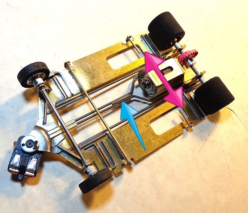
Flat MTT: I was running out of time by now so only got one short session. Target was 4.75.
The Purple Angel is an almost unique track in that I think only two were ever built. Other high speed tracks such as King tracks or hillclimbs are a series of fairly conventional simple 90°, 180°, and 270° corners joined by straightaways of various lengths. The Angel is different in that the track has one very high bank followed by a main straight after that. Then the rest of the track is a more or less continuous chain of interconnected corners. While the speeds are very fast (faster than any King in NorCal), the cars are constantly changing direction through the infield. This track is challenging to build for in that "high bite" cars often don't work as well as some more basic stiffer designs. Target time today for a Can Am was 5.0 sec. I was using a fresh motor in the GVP that was pretty good.
GVP: General characteristics.
- At a starting weight of 101.5 grams (no body) this car was very light for our venues here in NorCal.
- From the first few laps, it was obvious that the GVP can generate very high cornering speeds.
- It is exceptionally quick off the corner and thus feels very fast in the short straights.
- In stock form shown earlier, the best times were 5.15 with JK 8713, 9/27, and O/S Lola 163 body.
- As a counterpoint, the baseline car was running consistent at 5.05 with same body and tires.
- First step was to go to JK 8713T. Immediately the car was less critical and would exit more cleanly.
- Times dropped to 5.05 and were much more consistent with less tendency to deslot suddenly.
- Next, I tried an 8713T narrowed. This didn't change the times but the car felt easier.
- Next, I shortened the spoiler on the body from 1/2" to 3/8". Times went up slightly so I changed back.
- Added 3 grams to each pan in the spots shown below by the red arrows. Car was more comfortable at 5.01.
- Next I soldered in a "limiter" (blue arrow) and it all came together at 4.94 with several at 4.97-.98.
- Took the weight back off and the times stayed almost the same but the car was little touchy again.
- While the limiter was the bigger factor, I'd probably run the car with the weight as well.
- Very good race car in this configuration and track conditions.
Flat MTT: I was running out of time by now so only got one short session. Target was 4.75.
- With the limiter on but weight off, the GVP was pretty harsh on exit with 8/29. Times = 4.85 range.
- Weight back on and that helped quite a bit. Times dropped to 4.77 range. Still felt "too fast"
- Went to 7/29 and times stayed the same but car was a little more tractable on exit (still not real smooth).
- Gearing somewhere in between the 8/29 and 7/29
- More weight maybe 5 grams/side instead of the 3 grams.
- Longer body to smooth out the turn exit.
- Eventually, maybe a longer guide lead for the flat tracks.
- Maybe even try a slower motor...

- Cheater likes this
Jim Fowler
#48
Tim Neja
-

- Subscriber
-
- 6,846 posts Joined: 11-June 07
Grand Champion Poster
- Gender:Male
- Location:Paso Robles
Posted 24 November 2013 - 11:27 PM
Jim,
If you're adding lead to the back why not turn the pans around so the holes are towards the front?
T
If you're adding lead to the back why not turn the pans around so the holes are towards the front?
T
- Jim Lange likes this
She's real fine, my 409!!!

#50
JimF
-
- Full Member
-
- 2,220 posts Joined: 20-June 07
Posting Leader
- Gender:Male
Posted 25 November 2013 - 04:51 PM
Jim,
If you're adding lead to the back why not turn the pans around so the holes are towards the front?
T
Two reasons.
- One: when done this way, the front pin placement is a bit further aft than I like. Flipping the pans to move the windows makes the front pin placement even further back.
- Two: I have done a fair bit of experimentation recently with two scales. Taking the small amount of weight involved in the windows and moving it to the rear a net C.O.M. distance of 10mm or so, does not materially affect the fore/aft balance.
The subsequent versions of this kit have solved #1 and hence have also improved #2 to a point. For many track configurations and surface conditions, that will probably be enough. In a broader sense for the tracks and conditions that we see up here in NorKalli.........the guide lead is still a little short.
- JoB likes this
Jim Fowler


